Contents
- Configuring MST Using NX-OS
- Information About MST
- MST Overview
- MST Regions
- MST BPDUs
- MST Configuration Information
- IST, CIST, and CST
- IST, CIST, and CST Overview
- Spanning Tree Operation Within an MST Region
- Spanning Tree Operations Between MST Regions
- MST Terminology
- Hop Count
- Boundary Ports
- Detecting Unidirectional Link Failure:MST
- Port Cost and Port Priority
- Interoperability with IEEE 802.1D
- High Availability for MST
- Virtualization Support for MST
- Licensing Requirements for MST
- Prerequisites for MST
- Guidelines and Limitations for Configuring MST
- Configuring MST: Steps
- Enabling MST - CLI Version
- Entering MST Configuration Mode
- Specifying the MST Name
- Specifying the MST Configuration Revision Number
- Specifying the Configuration on an MST Region
- Mapping or Unmapping a VLAN to an MST Instance - CLI Version
- Mapping Secondary VLANs to Same MSTI as Primary VLANs for Private VLANs
- Configuring the Root Bridge
- Configuring an MST Secondary Root Bridge
- Configuring the MST Switch Priority
- Configuring the MST Port Priority
- Configuring the MST Port Cost
- Configuring the MST Hello Time
- Configuring the MST Forwarding-Delay Time
- Configuring the MST Maximum-Aging Time
- Configuring the MST Maximum-Hop Count
- Configuring an Interface to Proactively Send Prestandard MSTP Messages - CLI Version
- Specifying the Link Type for MST - CLI Version
- Reinitializing the Protocol for MST
- Verifying MST Configurations
- Displaying and Clearing MST Statistics -- CLI Version
- MST Example Configuration
- Default Settings for MST
- Additional References for MST -- CLI Version
- Feature History for Configuring MST--CLI Version
Configuring MST Using NX-OS
This chapter describes how to configure Multiple Spanning Tree (MST) on Cisco Nexus 7000 Series devices.
- Information About MST
- Licensing Requirements for MST
- Prerequisites for MST
- Guidelines and Limitations for Configuring MST
- Configuring MST: Steps
- Verifying MST Configurations
- Displaying and Clearing MST Statistics -- CLI Version
- MST Example Configuration
- Default Settings for MST
- Additional References for MST -- CLI Version
- Feature History for Configuring MST--CLI Version
- MST Overview
- MST Regions
- MST BPDUs
- MST Configuration Information
- IST, CIST, and CST
- Hop Count
- Boundary Ports
- Detecting Unidirectional Link Failure:MST
- Port Cost and Port Priority
- Interoperability with IEEE 802.1D
- High Availability for MST
- Virtualization Support for MST
- Enabling MST - CLI Version
- Entering MST Configuration Mode
- Specifying the MST Name
- Specifying the MST Configuration Revision Number
- Specifying the Configuration on an MST Region
- Mapping or Unmapping a VLAN to an MST Instance - CLI Version
- Mapping Secondary VLANs to Same MSTI as Primary VLANs for Private VLANs
- Configuring the Root Bridge
- Configuring an MST Secondary Root Bridge
- Configuring the MST Switch Priority
- Configuring the MST Port Priority
- Configuring the MST Port Cost
- Configuring the MST Hello Time
- Configuring the MST Forwarding-Delay Time
- Configuring the MST Maximum-Aging Time
- Configuring the MST Maximum-Hop Count
- Configuring an Interface to Proactively Send Prestandard MSTP Messages - CLI Version
- Specifying the Link Type for MST - CLI Version
- Reinitializing the Protocol for MST
Information About MST
Note
See the Cisco Nexus 7000 Series NX-OS Interfaces Configuration Guide, Release 4.2, for information on creating Layer 2 interfaces.
MST, which is the IEEE 802.1s standard, allows you to assign two or more VLANs to a spanning tree instance. MST is not the default spanning tree mode; Rapid per VLAN Spanning Tree (Rapid PVST+) is the default mode. MST instances with the same name, revision number, and VLAN-to-instance mapping combine to form an MST region. The MST region appears as a single bridge to spanning tree configurations outside the region. MST forms a boundary to that interface when it receives an IEEE 802.1D Spanning Tree Protocol (STP) message from a neighboring device.
Note
Spanning tree is used to refer to IEEE 802.1w and IEEE 802.1s. If the IEEE 802.1D Spanning Tree Protocol is discussed in this publication, 802.1D is stated specifically.
- MST Overview
- MST Regions
- MST BPDUs
- MST Configuration Information
- IST, CIST, and CST
- Hop Count
- Boundary Ports
- Detecting Unidirectional Link Failure:MST
- Port Cost and Port Priority
- Interoperability with IEEE 802.1D
- High Availability for MST
- Virtualization Support for MST
- IST, CIST, and CST Overview
- Spanning Tree Operation Within an MST Region
- Spanning Tree Operations Between MST Regions
- MST Terminology
MST Overview
Note
You must enable MST; Rapid PVST+ is the default spanning tree mode.
MST maps multiple VLANs into a spanning tree instance, with each instance having a spanning tree topology independent of other spanning tree instances. This architecture provides multiple forwarding paths for data traffic, enables load balancing, and reduces the number of STP instances required to support a large number of VLANs. MST improves the fault tolerance of the network because a failure in one instance (forwarding path) does not affect other instances (forwarding paths).
MST provides rapid convergence through explicit handshaking as each MST instance uses the IEEE 802.1w standard, which eliminates the 802.1D forwarding delay and quickly transitions root bridge ports and designated ports to the forwarding state.
MAC address reduction is always enabled on the device. You cannot disable this feature.
MST improves spanning tree operation and maintains backward compatibility with these STP versions:
Note
- IEEE 802.1w defined the Rapid Spanning Tree Protocol (RSTP) and was incorporated into IEEE 802.1D.
- IEEE 802.1s defined MST and was incorporated into IEEE 802.1Q.
MST Regions
To allow devices to participate in MST instances, you must consistently configure the devices with the same MST configuration information.
A collection of interconnected devices that have the same MST configuration is an MST region. An MST region is a linked group of MST bridges with the same MST configuration.
The MST configuration controls the MST region to which each device belongs. The configuration includes the name of the region, the revision number, and the VLAN-to-MST instance assignment mapping.
A region can have one or multiple members with the same MST configuration. Each member must be capable of processing 802.1w bridge protocol data units (BPDUs). There is no limit to the number of MST regions in a network.
Each device can support up to 65 MST instances (MSTIs), including Instance 0, in a single MST region. Instances are identified by any number in the range from 1 to 4094. The system reserves Instance 0 for a special instance, which is the IST. You can assign a VLAN to only one MST instance at a time.
The MST region appears as a single bridge to adjacent MST regions and to other Rapid PVST+ regions and 802.1D spanning tree protocols.
Note
We do not recommend that you partition the network into a large number of regions.
MST BPDUs
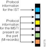
Each device has only one MST BPDU per interface, and that BPDU carries an M-record for each MSTI on the device. Only the IST sends BPDUs for the MST region; all M-records are encapsulated in that one BPDU that the IST sends. Because the MST BPDU carries information for all instances, the number of BPDUs that need to be processed to support MST is significantly reduced compared with Rapid PVST+.
MST Configuration Information
The MST configuration that must be identical on all devices within a single MST region is configured by the user.
You can configure the three parameters of the MST configuration as follows:
Name—32-character string, null padded and null terminated, identifying the MST region
Revision number—Unsigned 16-bit number that identifies the revision of the current MST configuration
Note
You must set the revision number when required as part of the MST configuration. The revision number is not incremented automatically each time that the MST configuration is committed.
VLAN-to-MST instance mapping—4096-element table that associates each of the potential 4094 VLANs supported in each VDC to a given instance with the first (0) and last element (4095) set to 0. The value of element number X represents the instance to which VLAN X is mapped.
Note
When you change the VLAN-to-MSTI mapping, the system reconverges MST.
MST BPDUs contain these three configuration parameters. An MST bridge accepts an MST BPDU into its own region only if these three configuration parameters match exactly. If one configuration attribute differs, the MST bridge considers the BPDU to be from another MST region.
IST, CIST, and CST
- IST, CIST, and CST Overview
- Spanning Tree Operation Within an MST Region
- Spanning Tree Operations Between MST Regions
- MST Terminology
IST, CIST, and CST Overview
Unlike Rapid PVST+, in which all the STP instances are independent, MST establishes and maintains IST, CIST, and CST spanning trees, as follows:
An IST is the spanning tree that runs in an MST region.
MST establishes and maintains additional spanning trees within each MST region; these spanning trees are called multiple spanning tree instances (MSTIs).
Instance 0 is a special instance for a region, known as the IST. The IST always exists on all ports; you cannot delete the IST, or Instance 0. By default, all VLANs are assigned to the IST. All other MST instances are numbered from 1 to 4094.
The IST is the only STP instance that sends and receives BPDUs. All of the other MSTI information is contained in MST records (M-records), which are encapsulated within MST BPDUs.
All MSTIs within the same region share the same protocol timers, but each MSTI has its own topology parameters, such as the root bridge ID, the root path cost, and so forth.
An MSTI is local to the region; for example, MSTI 9 in region A is independent of MSTI 9 in region B, even if regions A and B are interconnected. Only CST information crosses region boundaries.
The CST interconnects the MST regions and any instance of 802.1D and 802.1w STP that may be running on the network. The CST is the one STP instance for the entire bridged network and encompasses all MST regions and 802.1w and 802.1D instances.
A CIST is a collection of the ISTs in each MST region. The CIST is the same as an IST inside an MST region, and the same as a CST outside an MST region.
The spanning tree computed in an MST region appears as a subtree in the CST that encompasses the entire switched domain. The CIST is formed by the spanning tree algorithm running among devices that support the 802.1w, 802.1s, and 802.1D standards. The CIST inside an MST region is the same as the CST outside a region.
Spanning Tree Operation Within an MST Region
The IST connects all the MSTdevices in a region. When the IST converges, the root of the IST becomes the CIST regional root. The CIST regional root is also the CIST root if there is only one region in the network. If the CIST root is outside the region, the protocol selects one of the MST devices at the boundary of the region as the CIST regional root.
When an MST device initializes, it sends BPDUs that identify itself as the root of the CIST and the CIST regional root, with both the path costs to the CIST root and to the CIST regional root set to zero. The device also initializes all of its MSTIs and claims to be the root for all of them. If the device receives superior MSTI root information (lower switch ID, lower path cost, and so forth) than the information that is currently stored for the port, it relinquishes its claim as the CIST regional root.
During initialization, an MST region might have many subregions, each with its own CIST regional root. As devices receive superior IST information from a neighbor in the same region, they leave their old subregions and join the new subregion that contains the true CIST regional root. This action causes all subregions to shrink except for the subregion that contains the true CIST regional root.
All devices in the MST region must agree on the same CIST regional root. Any two devices in the region will only synchronize their port roles for an MSTI if they converge to a common CIST regional root.
Spanning Tree Operations Between MST Regions
If you have multiple regions or 802.1 w or 802.1D STP instances within a network, MST establishes and maintains the CST, which includes all MST regions and all 802.1w and 802.1D STP devices in the network. The MSTIs combine with the IST at the boundary of the region to become the CST.
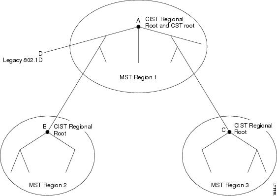
The IST connects all the MST devices in the region and appears as a subtree in the CIST that encompasses the entire switched domain. The root of the subtree is the CIST regional root. The MST region appears as a virtual device to adjacent STP devices and MST regions.
This figure shows a network with three MST regions and an 802.1D device (D). The CIST regional root for region 1 (A) is also the CIST root. The CIST regional root for region 2 (B) and the CIST regional root for region 3 (C) are the roots for their respective subtrees within the CIST.
Figure 2. MST Regions, CIST Regional Roots, and CST Root
Only the CST instance sends and receives BPDUs. MSTIs add their spanning tree information into the BPDUs (as M-records) to interact with neighboring devices within the same MST region and compute the final spanning tree topology. Because of this, the spanning tree parameters related to the BPDU transmission (for example, hello time, forward time, max-age, and max-hops) are configured only on the CST instance but affect all MSTIs. You can configure the parameters related to the spanning tree topology (for example, the switch priority, the port VLAN cost, and the port VLAN priority) on both the CST instance and the MSTI.
MST devices use Version 3 BPDUs. If the MST device falls back to 802.1D STP, the device uses only 802.1D BPDUs to communicate with 802.1D-only devices. MST devices use MST BPDUs to communicate with MST devices.
MST Terminology
MST naming conventions include identification of some internal or regional parameters. These parameters are used only within an MST region, compared to external parameters that are used throughout the whole network. Because the CIST is the only spanning tree instance that spans the whole network, only the CIST parameters require the external qualifiers and not the internal or regional qualifiers. The MST terminology is as follows:
The CIST root is the root bridge for the CIST, which is the unique instance that spans the whole network.
The CIST external root path cost is the cost to the CIST root. This cost is left unchanged within an MST region. An MST region looks like a single device to the CIST. The CIST external root path cost is the root path cost calculated between these virtual devices and devices that do not belong to any region.
If the CIST root is in the region, the CIST regional root is the CIST root. Otherwise, the CIST regional root is the closest device to the CIST root in the region. The CIST regional root acts as a root bridge for the IST.
The CIST internal root path cost is the cost to the CIST regional root in a region. This cost is only relevant to the IST, instance 0.
Hop Count
MST does not use the message-age and maximum-age information in the configuration BPDU to compute the STP topology inside the MST region. Instead, the protocol uses the path cost to the root and a hop-count mechanism similar to the IP time-to-live (TTL) mechanism.
By using the spanning-tree mst max-hops global configuration command, you can configure the maximum hops inside the region and apply it to the IST and all MST instances in that region.
The hop count achieves the same result as the message-age information (triggers a reconfiguration). The root bridge of the instance always sends a BPDU (or M-record) with a cost of 0 and the hop count set to the maximum value. When a device receives this BPDU, it decrements the received remaining hop count by one and propagates this value as the remaining hop count in the BPDUs that it generates. When the count reaches zero, the device discards the BPDU and ages the information held for the port.
The message-age and maximum-age information in the 802.1w portion of the BPDU remain the same throughout the region (only on the IST), and the same values are propagated by the region-designated ports at the boundary.
You configure a maximum aging time as the number of seconds that a device waits without receiving spanning tree configuration messages before attempting a reconfiguration.
Boundary Ports
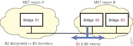
A boundary port is a port that connects to a LAN, the designated bridge of which is either a bridge with a different MST configuration (and so, a separate MST region) or a Rapid PVST+ or 802.1D STP bridge. A designated port knows that it is on the boundary if it detects an STP bridge or receives an agreement proposal from an MST bridge with a different configuration or a Rapid PVST+ bridge. This definition allows two ports that are internal to a region to share a segment with a port that belongs to a different region, creating the possibility of receiving both internal and external messages on a port.
At the boundary, the roles of MST ports do not matter; the system forces their state to be the same as the IST port state. If the boundary flag is set for the port, the MST port-role selection process assigns a port role to the boundary and assigns the same state as the state of the IST port. The IST port at the boundary can take up any port role except a backup port role.
Detecting Unidirectional Link Failure:MST
Currently, this feature is not present in the IEEE MST standard, but it is included in the standard-compliant implementation; it is based on the dispute mechanism. The software checks the consistency of the port role and state in the received BPDUs to detect unidirectional link failures that could cause bridging loops. This feature is based on the dispute mechanism.
Note
See the Cisco Nexus 7000 Series NX-OS Interfaces Configuration Guide, Release 4.2 for information on Unidirectional Link Detection (UDLD)
When a designated port detects a conflict, it keeps its role, but reverts to a discarding state because disrupting connectivity in case of inconsistency is preferable to opening a bridging loop.
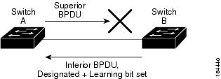
This figure shows a unidirectional link failure that typically creates a bridging loop. Switch A is the root bridge, and its BPDUs are lost on the link leading to switch B. Rapid PVST+ (802.1w) and MST BPDUs include the role and state of the sending port. With this information, switch A can detect that switch B does not react to the superior BPDUs that it sends and that switch B is the designated, not root port. As a result, switch A blocks (or keeps blocking) its port, which prevents the bridging loop.
Figure 4. Detecting a Unidirectional Link Failure
Port Cost and Port Priority
Spanning tree uses port costs to break a tie for the designated port. Lower values indicate lower port costs, and spanning tree chooses the least costly path. Default port costs are taken from the bandwidth of the interface, as follows:
You can configure the port costs in order to influence which port is chosen.
Note
MST always uses the long path-cost calculation method, so the range of valid values is between 1 and 200,000,000.
The system uses port priorities to break ties among ports with the same cost. A lower number indicates a higher priority. The default port priority is 128. You can configure the priority to values between 0 and 224, in increments of 32.
Interoperability with IEEE 802.1D
A device that runs MST supports a built-in protocol migration feature that enables it to interoperate with 802.1D STP devices. If this devoce receives an 802.1D configuration BPDU (a BPDU with the protocol version set to 0), it sends only 802.1D BPDUs on that port. In addition, an MST device can detect that a port is at the boundary of a region when it receives an 802.1D BPDU, an MST BPDU (Version 3) associated with a different region, or an 802.1w BPDU (Version 2).
However, the device does not automatically revert to the MST mode if it no longer receives 802.1D BPDUs because it cannot detect whether the 802.1D device has been removed from the link unless the 802.1D device is the designated device. A device might also continue to assign a boundary role to a port when the device to which this device is connected has joined the region.
To restart the protocol migration process (force the renegotiation with neighboring devices), enter the clear spanning-tree detected-protocols command.
All Rapid PVST+ switches (and all 8021.D STP switches) on the link can process MST BPDUs as if they are 802.1w BPDUs. MST devices can send either Version 0 configuration and topology change notification (TCN) BPDUs or Version 3 MST BPDUs on a boundary port. A boundary port connects to a LAN, the designated device of which is either a single spanning tree device or a device with a different MST configuration.
MST interoperates with the Cisco prestandard MSTP whenever it receives prestandard MSTP on an MST port; no explicit configuration is necessary. In Cisco NX-OS Release 4.0(2) and later releases, you can configure specified interfaces to send prestandard MSTP messages all the time; it does not have to wait to receive a prestandard MST message to begin sending prestandard MST messages.
You can also configure the interface to proactively send prestandard MSTP messages.
High Availability for MST
The software supports high availability for MST. However, the statistics and timers are not restored when MST restarts. The timers start again and the statistics begin from 0.
The device supports full nondisruptive upgrades for MST. See the Cisco Nexus 7000 Series NX-OS High Availability and Redundancy Guide, Release 4.2 for complete information on nondisruptive upgrades and high-availability features.
Virtualization Support for MST
The system provides support for virtual device contexts (VDCs), and each VDC runs a separate STP.
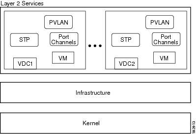
You can run Rapid PVST+ in one VDC and run MST in another VDC as shown in this figure. Each VDC will have its own MST. Ensure that you are in the correct VDC.
For example, VDC1 can run MST, VDC2 can run Rapid PVST+, and VDC 3 can run MST.
Figure 5. Separate STP in each VDC
Note
MSTs in different VDCs are distinct, which meant that you have to perform MST region configuration for each VDC.
Note
See the Cisco Nexus 7000 Series NX-OS Virtual Device Context Configuration Guide, Release 4.2, for complete information on VDCs and assigning resources.
Licensing Requirements for MST
The following table shows the licensing requirements for this feature:
Product
License Requirement
NX-OS
MST requires no license. Any feature not included in a license package is bundled with the Cisco NX-OS system images and is provided at no extra charge to you. For a complete explanation of the NX-OS licensing scheme, see theCisco Nexus 7000 Series NX-OS Licensing Guide, Release 4.2.
However, using VDCs requires an Advanced Services license.
Guidelines and Limitations for Configuring MST
Note
When you change the VLAN-to-MSTI mapping, the system reconverges MST.
Follow these guidelines when using MST:
You must enable MST; Rapid PVST+ is the default spanning tree mode.
You can assign a VLAN to only one MST instance at a time.
You cannot map VLANs 3968 to 4047 or 4094 to an MST instance. These VLANs are reserved for internal use by the device.
You can have up to 65 MST instances on one device.
The maximum number of VLANs and ports is 75,000.
By default, all VLANs are mapped to MSTI 0 or the IST.
When you are working with private VLANs on the system, ensure that all secondary VLANs are mapped to the same MSTI as the primary VLAN.
You can load balance only within the MST region.
Ensure that trunks carry all of the VLANs that are mapped to an MSTI or exclude all those VLANs that are mapped to an MSTI.
Always leave STP enabled.
Do not change timers because you can adversely affect your network stability.
Keep user traffic off the management VLAN; keep the management VLAN separate from user data.
Choose the distribution and core layers as the location of the primary and secondary root switches.
Port channeling—The port channel bundle is considered as a single port. The port cost is the aggregation of all the configured port costs assigned to that channel.
When you map a VLAN to an MSTI, the system automatically removes that VLAN from its previous MSTI.
You can map any number of VLANs to an MSTI.
All MST boundary ports must be forwarding for load balancing between Rapid PVST+ and an MST cloud or between a PVST+ and an MST cloud. The CIST regional root of the MST cloud must be the root of the CST. If the MST cloud consists of multiple MST regions, one of the MST regions must contain the CST root and all of the other MST regions must have a better path to the root contained within the MST cloud than a path through the Rapid PVST+ or PVST+ cloud.
Do not partition the network into a large number of regions. However, if this situation is unavoidable, we recommend that you partition the switched LAN into smaller LANs interconnected by non-Layer 2 devices.
When you work with private VLANs, enter the private-vlan synchronize command to map the secondary VLANs to the same MST instance as the primary VLAN.
When you are in the MST configuration submode, the following guidelines apply:
Each command reference line creates its pending regional configuration.
The pending region configuration starts with the current region configuration.
To leave the MST configuration submode without committing any changes, enter the abort command.
To leave the MST configuration submode and commit all the changes that you made before you left the submode, enter the exit or end commands, or press Ctrl + Z.
Note
The software supports full nondisruptive upgrades for MST. See Cisco Nexus 7000 Series NX-OS High Availability and Redundancy Guide, Release 4.2, for complete information on nondisruptive upgrades.
Configuring MST: Steps
- Enabling MST - CLI Version
- Entering MST Configuration Mode
- Specifying the MST Name
- Specifying the MST Configuration Revision Number
- Specifying the Configuration on an MST Region
- Mapping or Unmapping a VLAN to an MST Instance - CLI Version
- Mapping Secondary VLANs to Same MSTI as Primary VLANs for Private VLANs
- Configuring the Root Bridge
- Configuring an MST Secondary Root Bridge
- Configuring the MST Switch Priority
- Configuring the MST Port Priority
- Configuring the MST Port Cost
- Configuring the MST Hello Time
- Configuring the MST Forwarding-Delay Time
- Configuring the MST Maximum-Aging Time
- Configuring the MST Maximum-Hop Count
- Configuring an Interface to Proactively Send Prestandard MSTP Messages - CLI Version
- Specifying the Link Type for MST - CLI Version
- Reinitializing the Protocol for MST
Enabling MST - CLI Version
ProcedureYou can enable MST; Rapid PVST+ is the default.
You cannot simultaneously run MST and Rapid PVST+ on the same VDC.
Note
When you change the spanning tree mode, traffic is disrupted because all spanning tree instances are stopped for the previous mode and started for the new mode.
Entering MST Configuration Mode
ProcedureYou enter MST configuration mode to configure the MST name, VLAN-to-instance mapping, and MST revision number on the device.
If two or more devices are in the same MST region, they must have the identical MST name, VLAN-to-instance mapping, and MST revision number.
Note
Each command reference line creates its pending regional configuration in MST configuration mode. In addition, the pending region configuration starts with the current region configuration.
Command or Action Purpose Step 1 config t
Example:switch# config t switch(config)#Enters configuration mode.
Step 2 Enter one of the following commands:
Option Description spanning-tree mst configuration Enters MST configuration submode on the system. You must be in the MST configuration submode to assign the MST configuration parameters, as follows:
no spanning-tree mst configuration Returns the MST region configuration to the following default values:
Example:switch(config)# spanning-tree mst configuration switch(config-mst)#Step 3 Enter one of the following commands:
Option Description exit Commits all the changes and exits MST configuration submode.
abort Exits the MST configuration submode without committing any of the changes.
Example:switch(config-mst)# exit switch(config)#Step 4 copy running-config startup-config
Example:switch(config)# copy running-config startup-config(Optional) Copies the running configuration to the startup configuration.
Specifying the MST Name
ProcedureYou can configure a region name on the bridge. If two or more bridges are in the same MST region, they must have the identical MST name, VLAN-to-instance mapping, and MST revision number.
Command or Action Purpose Step 1 config t
Example:switch# config t switch(config)#Enters configuration mode.
Step 2 spanning-tree mst configuration
Example:switch(config)# spanning-tree mst configuration switch(config-mst)#Enters MST configuration submode.
Step 3 name name
Example:switch(config-mst)# name accountingSpecifies the name for the MST region. The name string has a maximum length of 32 characters and is case sensitive. The default is an empty string.
Step 4 Enter one of the following commands:
Option Description exit Commits all the changes and exits MST configuration submode.
abort Exits the MST configuration submode without committing any of the changes.
Example:switch(config-mst)# exit switch(config)#Step 5 show spanning-tree mst
Example:switch# show spanning-tree mst(Optional) Displays the MST configuration.
Step 6 copy running-config startup-config
Example:switch(config)# copy running-config startup-config(Optional) Copies the running configuration to the startup configuration.
Specifying the MST Configuration Revision Number
ProcedureYou configure the revision number on the bridge. If two or more bridges are in the same MST region, they must have the identical MST name, VLAN-to-instance mapping, and MST revision number.
Command or Action Purpose Step 1 config t
Example:switch# config t switch(config)#Enters configuration mode.
Step 2 spanning-tree mst configuration
Example:switch(config)# spanning-tree mst configuration switch(config-mst)#Enters MST configuration submode.
Step 3 revision version
Example:switch(config-mst)# revision 5Specifies the revision number for the MST region. The range is from 0 to 65535, and the default value is 0.
Step 4 Enter one of the following commands:
Option Description exit Commits all the changes and exits MST configuration submode.
abort Exits the MST configuration submode without committing any of the changes.
Example:switch(config-mst)# exit switch(config)#Step 5 show spanning-tree mst
Example:switch# show spanning-tree mst(Optional) Displays the MST configuration.
Step 6 copy running-config startup-config
Example:switch(config)# copy running-config startup-config(Optional) Copies the running configuration to the startup configuration.
Specifying the Configuration on an MST Region
ProcedureIf two or more devices are to be in the same MST region, they must have the same VLAN-to-instance mapping, the same configuration revision number, and the same MST name.
A region can have one member or multiple members with the same MST configuration; each member must be capable of processing IEEE 802.1w RSTP BPDUs. There is no limit to the number of MST regions in a network, but each region can support only up to 65 MST instances. You can assign a VLAN to only one MST instance at a time.
Command or Action Purpose Step 1 config t
Example:switch# config t switch(config)#Enters configuration mode.
Step 2 spanning-tree mst configuration
Example:switch(config)# spanning-tree mst configuration switch(config-mst)#Enters MST configuration submode.
Step 3 instance instance-id vlan vlan-range
Example:switch(config-mst)# instance 1 vlan 10-20Maps VLANs to an MST instance as follows:
For instance-id, the range is from 1 to 4094.
For vlan vlan-range, the range is from 1 to 4094. When you map VLANs to an MST instance, the mapping is incremental, and the VLANs specified in the command are added to or removed from the VLANs that were previously mapped.
To specify a VLAN range, enter a hyphen; for example, enter the instance 1 vlan 1-63 command to map VLANs 1 through 63 to MST instance 1.
To specify a VLAN series, enter a comma; for example, enter the instance 1 vlan 10, 20, 30 command to map VLANs 10, 20, and 30 to MST instance 1.
Step 4 name name
Example:switch(config-mst)# name region1Specifies the instance name. The name string has a maximum length of 32 characters and is case sensitive.
Step 5 revision version
Example:switch(config-mst)# revision 1Specifies the configuration revision number. The range is from 0 to 65535.
Step 6 Enter one of the following commands:
Option Description exit Commits all the changes and exits MST configuration submode.
abort Exits the MST configuration submode without committing any of the changes.
Example:switch(config-mst)# exit switch(config)#Step 7 show spanning-tree mst
Example:switch# show spanning-tree mst(Optional) Displays the MST configuration.
Step 8 copy running-config startup-config
Example:switch(config)# copy running-config startup-config(Optional) Copies the running configuration to the startup configuration.
This example shows how to enter MST configuration mode, map VLANs 10 to 20 to MST instance 1, name the region region1, set the configuration revision to 1, display the pending configuration, apply the changes, and return to global configuration mode:
switch#spanning-tree mst configuration switch(config-mst)#instance 1 vlan 10-20 switch(config-mst)#name region1 switch(config-mst)#revision 1 switch(config-mst#)show pending Pending MST configuration Name [region1] Revision 1 Instances configured 2 Instance Vlans Mapped -------- --------------------- 0 1-9,21-4094 1 10-20 ------------------------------- switch(config-mst)#exit switch(config)#Mapping or Unmapping a VLAN to an MST Instance - CLI Version
ProcedureIf two or more bridges are to be in the same MST region, they must have the identical MST name, VLAN-to-instance mapping, and MST revision number.
You cannot map VLANs 3968 to 4047 or 4094 to any MST instance. These VLANs are reserved for internal use by the device.
Note
When you change the VLAN-to-MSTI mapping, the system reconverges MST.
Note
You cannot disable an MSTI.
Command or Action Purpose Step 1 config t
Example:switch# config t switch(config)#Enters configuration mode.
Step 2 spanning-tree mst configuration
Example:switch(config)# spanning-tree mst configuration switch(config-mst)#Enters MST configuration submode.
Step 3 Enter one of the following commands:
Option Description instance instance-id vlan vlan-range Maps VLANs to an MST instance as follows:
For instance_id, the range is from 1 to 4094. Instance 0 is reserved for the IST for each MST region.
For vlan-range, the range is from 1 to 4094.
When you map VLANs to an MSTI, the mapping is incremental, and the VLANs specified in the command are added to or removed from the VLANs that were previously mapped.
no instance instance-id vlan vlan-range Deletes the specified instance and returns the VLANs to the default MSTI, which is the CIST.
Example:switch(config-mst)# instance 3 vlan 200Step 4 Enter one of the following commands:
Option Description exit Commits all the changes and exits MST configuration submode.
abort Exits the MST configuration submode without committing any of the changes.
Example:switch(config-mst)# exit switch(config)#Step 5 show spanning-tree mst
Example:switch# show spanning-tree mst(Optional) Displays the MST configuration.
Step 6 copy running-config startup-config
Example:switch(config)# copy running-config startup-config(Optional) Copies the running configuration to the startup configuration.
Mapping Secondary VLANs to Same MSTI as Primary VLANs for Private VLANs
ProcedureWhen you are working with private VLANs on the system, all secondary VLANs must be in the same MSTI as their associated primary VLAN. Enter the private-vlan synchronize command to accomplish this synchronization automatically.
Command or Action Purpose Step 1 config t
Example:switch# config t switch(config)#Enters configuration mode.
Step 2 spanning-tree mst configuration
Example:switch(config)# spanning-tree mst configuration switch(config-mst)#Enters MST configuration submode.
Step 3 private-vlan synchronize
Example:g-mst)# private-vlan synchronizeAutomatically maps all secondary VLANs to the same MSTI as their associated primary VLAN for all private VLANs.
Step 4 Enter one of the following commands:
Option Description exit Commits all the changes and exits MST configuration submode.
abort Exits the MST configuration submode without committing any of the changes.
Example:switch(config-mst)# exit switch(config)#Step 5 show spanning-tree mst
Example:switch# show spanning-tree mst(Optional) Displays the MST configuration.
Step 6 copy running-config startup-config
Example:switch(config)# copy running-config startup-config(Optional) Copies the running configuration to the startup configuration.
Configuring the Root Bridge
ProcedureYou can configure the device to become the MST root bridge.
The spanning-tree vlan vlan_ID primary root command fails if the value required to be the root bridge is less than 4096. If the software cannot lower the bridge priority any lower, the device returns the following message:
Error: Failed to set root bridge for VLAN 1
It may be possible to make the bridge root by setting the priority
for some (or all) of these instances to zero.
Note
The root bridge for each MSTI should be a backbone or distribution device. Do not configure an access device as the spanning tree primary root bridge.
Enter the diameter keyword, which is available only for MSTI 0 (or the IST), to specify the Layer 2 network diameter (that is, the maximum number of Layer 2 hops between any two end stations in the Layer 2 network). When you specify the network diameter, the device automatically sets an optimal hello time, forward-delay time, and maximum-age time for a network of that diameter, which can significantly reduce the convergence time. You can enter the hello keyword to override the automatically calculated hello time.
Note
With the device configured as the root bridge, do not manually configure the hello time, forward-delay time, and maximum-age time using the spanning-tree mst hello-time, spanning-tree mst forward-time, and spanning-tree mst max-age global configuration commands.
Command or Action Purpose Step 1 config t
Example:switch# config t switch(config)#Enters configuration mode.
Step 2 Enter one of the following commands:
Option Description spanning-tree mst instance-id root {primary | secondary} [diameter dia [hello-time hello-time]] Configures a device as the root bridge as follows:
For instance-id, specify a single instance, a range of instances separated by a hyphen, or a series of instances separated by a comma. The range is from 1 to 4094.
For diameter net-diameter, specify the maximum number of Layer 2 hops between any two end stations. The default is 7. This keyword is available only for MST instance 0.
For hello-time seconds, specify the interval in seconds between the generation of configuration messages by the root bridge. The range is from 1 to 10 seconds; the default is 2 seconds.
no spanning-tree mst instance-id root Returns the switch priority, diameter, and hello time to default values.
Example:switch(config)# spanning-tree mst 5 root primaryStep 3 Enter one of the following commands:
Option Description exit Commits all the changes and exits MST configuration submode.
abort Exits the MST configuration submode without committing any of the changes.
Example:switch(config)# exit switch#Step 4 show spanning-tree mst
Example:switch# show spanning-tree mst(Optional) Displays the MST configuration.
Step 5 copy running-config startup-config
Example:switch(config)# copy running-config startup-config(Optional) Copies the running configuration to the startup configuration.
Configuring an MST Secondary Root Bridge
ProcedureYou use this command on more than one device to configure multiple backup root bridges. Enter the same network diameter and hello-time values that you used when you configured the primary root bridge with the spanning-tree mst root primary global configuration command.
Command or Action Purpose Step 1 config t
Example:switch# config t switch(config)#Enters configuration mode.
Step 2 Enter one of the following commands:
Option Description spanning-tree mst instance-id root {primary | secondary} [diameter dia[hello-time hello-time]] Configures a device as the secondary root bridge as follows:
For instance-id, you can specify a single instance, a range of instances separated by a hyphen, or a series of instances separated by a comma. The range is from 1 to 4094.
For diameter net-diameter, specify the maximum number of Layer 2 hops between any two end stations. The default is 7. This keyword is available only for MST instance 0.
For hello-time seconds, specify the interval in seconds between the generation of configuration messages by the root bridge. The range is from 1 to 10 seconds; the default is 2 seconds.
no spanning-tree mst instance-id root Returns the switch priority, diameter, and hello-time to default values.
Example:switch(config)# spanning-tree mst 5 root secondaryStep 3 exit
Example:switch# exit switch(config)#Exits configuration mode.
Step 4 show spanning-tree mst
Example:switch# show spanning-tree mst(Optional) Displays the MST configuration.
Step 5 copy running-config startup-config
Example:switch(config)# copy running-config startup-config(Optional) Copies the running configuration to the startup configuration.
Configuring the MST Switch Priority
ProcedureYou can configure the switch priority for an MST instance so that it is more likely that the specified device is chosen as the root bridge.
Note
Be careful when using the spanning-tree mst priority command. For most situations, we recommend that you enter the spanning-tree mst root primary and the spanning-tree mst root secondary global configuration commands to modify the switch priority.
Command or Action Purpose Step 1 config t
Example:switch# config t switch(config)#Enters configuration mode.
Step 2 spanning-tree mst instance-id priority priority-value
Example:switch(config)# spanning-tree mst 5 priority 4096Configures a device priority as follows:
For instance-id, you can specify a single instance, a range of instances separated by a hyphen, or a series of instances separated by a comma. The range is from 1 to 4094.
For priority-value the range is from 0 to 61440 in increments of 4096; the default is 32768. A lower number indicates that the device will most likely be chosen as the root bridge.
Priority values are 0, 4096, 8192, 12288, 16384, 20480, 24576, 28672, 32768, 36864, 40960, 45056, 49152, 53248, 57344, and 61440. The system rejects all other values.
Step 3 exit
Example:switch(config)# exit switch#Exits configuration mode.
Step 4 show spanning-tree mst
Example:switch# show spanning-tree mst(Optional) Displays the MST configuration.
Step 5 copy running-config startup-config
Example:switch(config)# copy running-config startup-config(Optional) Copies the running configuration to the startup configuration.
Configuring the MST Port Priority
ProcedureIf a loop occurs, MST uses the port priority when selecting an interface to put into the forwarding state. You can assign lower priority values to interfaces that you want selected first and higher priority values to the interface that you want selected last. If all interfaces have the same priority value, MST puts the interface with the lowest interface number in the forwarding state and blocks the other interfaces.
Command or Action Purpose Step 1 config t
Example:switch# config t switch(config)#Enters configuration mode.
Step 2 interface {{type slot/port} | {port-channel number}}
Example:switch(config)# interface ethernet 3/1 switch(config-if)#Specifies an interface to configure, and enters interface configuration mode.
Step 3 spanning-tree mst instance-id port-priority priority
Example:switch(config-if)# spanning-tree mst 3 port-priority 64Configures the port priority as follows:
For instance-id, you can specify a single MSTI, a range of MSTIs separated by a hyphen, or a series of MSTIs separated by a comma. The range is from 1 to 4094.
For priority, the range is from 0 to 224 in increments of 32. The default is 128. A lower number indicates a higher priority.
The priority values are 0, 32, 64, 96, 128, 160, 192, and 224. The system rejects all other values.
Step 4 exit
Example:switch(config-if)# exit switch(config)#Exits interface mode.
Step 5 show spanning-tree mst
Example:switch# show spanning-tree mst(Optional) Displays the MST configuration.
Step 6 copy running-config startup-config
Example:switch(config)# copy running-config startup-config(Optional) Copies the running configuration to the startup configuration.
Configuring the MST Port Cost
ProcedureThe MST port cost default value is derived from the media speed of an interface. If a loop occurs, MST uses the cost when selecting an interface to put in the forwarding state. You can assign lower cost values to interfaces that you want selected first and higher cost to interfaces values that you want selected last. If all interfaces have the same cost value, MST puts the interface with the lowest interface number in the forwarding state and blocks the other interfaces.
Note
MST uses the long path-cost calculation method.
Command or Action Purpose Step 1 config t
Example:switch# config t switch(config)#Enters configuration mode.
Step 2 interface {{type slot/port} | {port-channel number}}
Example:switch# config t switch(config)# interface ethernet 3/1 switch(config-if)#Specifies an interface to configure, and enters interface configuration mode.
Step 3 spanning-tree mst instance-id cost {cost | auto}
Example:switch(config-if)# spanning-tree mst 4 cost 17031970Configures the cost.
If a loop occurs, MST uses the path cost when selecting an interface to place into the forwarding state. A lower path cost represents higher-speed transmission as follows:
Step 4 exit
Example:switch(config-if)# exit switch(config)#Exits interface mode.
Step 5 show spanning-tree mst
Example:switch# show spanning-tree mst(Optional) Displays the MST configuration.
Step 6 copy running-config startup-config
Example:switch(config)# copy running-config startup-config(Optional) Copies the running configuration to the startup configuration.
Configuring the MST Hello Time
ProcedureYou can configure the interval between the generation of configuration messages by the root bridge for all instances on the device by changing the hello time.
Note
Be careful when using the spanning-tree mst hello-time command. For most situations, we recommend that you enter the spanning-tree mst instance-id root primary and the spanning-tree mst instance-id root secondary global configuration commands to modify the hello time.
Command or Action Purpose Step 1 config t
Example:switch# config t switch(config)#Enters configuration mode.
Step 2 spanning-tree mst hello-time seconds
Example:switch(config)# spanning-tree mst hello-time 1Configures the hello time for all MST instances. The hello time is the interval between the generation of configuration messages by the root bridge. These messages mean that the device is alive. For seconds, the range is from 1 to 10, and the default is 2 seconds.
Step 3 exit
Example:switch(config)# exit switch#Exits configuration mode.
Step 4 show spanning-tree mst
Example:switch# show spanning-tree mst(Optional) Displays the MST configuration.
Step 5 copy running-config startup-config
Example:switch(config)# copy running-config startup-config(Optional) Copies the running configuration to the startup configuration.
Configuring the MST Forwarding-Delay Time
Before You BeginProcedureEnsure that you are in the correct VDC (or enter the switchto vdcswitchto vdc command).
Command or Action Purpose Step 1 config t
Example:switch# config t switch(config)#Enters configuration mode.
Step 2 spanning-tree mst forward-time seconds
Example:switch(config)# spanning-tree mst forward-time 10Configures the forward time for all MST instances. The forward delay is the number of seconds that a port waits before changing from its spanning tree blocking and learning states to the forwarding state. For seconds, the range is from 4 to 30, and the default is 15 seconds.
Step 3 exit
Example:switch(config)# exit switch#Exits configuration mode.
Step 4 show spanning-tree mst
Example:switch# show spanning-tree mst(Optional) Displays the MST configuration.
Step 5 copy running-config startup-config
Example:switch(config)# copy running-config startup-config(Optional) Copies the running configuration to the startup configuration.
Configuring the MST Maximum-Aging Time
ProcedureYou can set the maximum-aging timer for all MST instances on the device with one command (the maximum age time only applies to the IST).
The maximum-aging timer is the number of seconds that a device waits without receiving spanning tree configuration messages before attempting a reconfiguration.
Command or Action Purpose Step 1 config t
Example:switch# config t switch(config)#Enters configuration mode.
Step 2 spanning-tree mst max-age seconds
Example:switch(config)# spanning-tree mst max-age 40Configures the maximum-aging time for all MST instances. The maximum-aging time is the number of seconds that a device waits without receiving spanning tree configuration messages before attempting a reconfiguration. For seconds, the range is from 6 to 40, and the default is 20 seconds.
Step 3 exit
Example:switch(config)# exit switch#Exits configuration mode.
Step 4 show spanning-tree mst
Example:switch# show spanning-tree mst(Optional) Displays the MST configuration.
Step 5 copy running-config startup-config
Example:switch(config)# copy running-config startup-config(Optional) Copies the running configuration to the startup configuration.
Configuring the MST Maximum-Hop Count
ProcedureYou can configure the maximum hops inside the region and apply it to the IST and all MST instances in that region. MST uses the path cost to the IST regional root and a hop-count mechanism similar to the IP time-to-live (TTL) mechanism. The hop count achieves the same result as the message-age information (triggers a reconfiguration).
Command or Action Purpose Step 1 config t
Example:switch# config t switch(config)#Enters configuration mode.
Step 2 spanning-tree mst max-hops hop-count
Example:switch(config)# spanning-tree mst max-hops 40Specifies the number of hops in a region before the BPDU is discarded and the information held for a port is aged. For hop-count, the range is from 1 to 255, and the default value is 20 hops.
Step 3 exit
Example:switch(config-mst)# exit switch#Exits configuration mode.
Step 4 show spanning-tree mst
Example:switch# show spanning-tree mst(Optional) Displays the MST configuration.
Step 5 copy running-config startup-config
Example:switch(config)# copy running-config startup-config(Optional) Copies the running configuration to the startup configuration.
Configuring an Interface to Proactively Send Prestandard MSTP Messages - CLI Version
ProcedureBy default, interfaces on a device running MST send prestandard, rather than standard, MSTP messages after they receive a prestandard MSTP message from another interface. In Cisco NX-OS Release 4.0(2) and later releases, you can configure the interface to proactively send prestandard MSTP messages. That is, the specified interface would not have to wait to receive a prestandard MSTP message; the interface with this configuration always sends prestandard MSTP messages.
Command or Action Purpose Step 1 config t
Example:switch# config t switch(config)#Enters configuration mode.
Step 2 interface type slot/port
Example:switch(config)# interface ethernet 1/4 switch(config-if)#Specifies the interface to configure and enters the interface configuration mode.
Step 3 spanning-tree mst pre-standard [interface {{ type slot/port} | {port-channel number}}] [detail]
Example:switch(config-if)# spanning-tree mst pre-standardSpecifies that the interface always sends MSTP messages in the prestandard format, rather than in the MSTP standard format.
Step 4 exit
Example:switch(config-if)# exit switch(config)#Exits interface mode.
Step 5 show spanning-tree mst
Example:switch# show spanning-tree mst(Optional) Displays the MST configuration.
Step 6 copy running-config startup-config
Example:switch(config)# copy running-config startup-config(Optional) Copies the running configuration to the startup configuration.
Specifying the Link Type for MST - CLI Version
ProcedureRapid connectivity (802.1w standard) is established only on point-to-point links. By default, the link type is controlled from the duplex mode of the interface. A full-duplex port is considered to have a point-to-point connection; a half-duplex port is considered to have a shared connection.
If you have a half-duplex link physically connected point to point to a single port on a remote device, you can override the default setting on the link type and enable rapid transitions.
If you set the link to shared, STP falls back to 802.1D.
Command or Action Purpose Step 1 config t
Example:switch# config t switch(config)#Enters configuration mode.
Step 2 interface type slot/port
Example:switch(config)# interface ethernet 1/4 switch(config-if)#Specifies the interface to configure and enters the interface configuration mode.
Step 3 spanning-tree link-type {auto | point-to-point | shared}
Example:switch(config-if)# spanning-tree link-type point-to-pointConfigures the link type to be either a point-to-point link or shared link. The system reads the default value from the device connection, as follows: half duplex links are shared and full-duplex links are point to point. If the link type is shared, the STP falls back to 802.1D. The default is auto, which sets the link type based on the duplex setting of the interface
Step 4 exit
Example:switch(config-if)# exit switch(config)#Exits interface mode.
Step 5 show spanning-tree
Example:switch# show spanning-tree(Optional) Displays the STP configuration.
Step 6 copy running-config startup-config
Example:switch(config)# copy running-config startup-config(Optional) Copies the running configuration to the startup configuration.
Reinitializing the Protocol for MST
ProcedureAn MST bridge can detect that a port is at the boundary of a region when it receives a legacy BPDU or an MST BPDU that is associated with a different region. However, the STP protocol migration cannot determine whether the legacy device, which is a device that runs only IEEE 802.1D, has been removed from the link unless the legacy device is the designated switch. Enter this command to reinitialize the protocol negotiation (force the renegotiation with neighboring devices) on the entire device or on specified interfaces.
Command or Action Purpose Step 1 clear spanning-tree detected-protocol [interface interface [interface-num | port-channel]]
Example:switch# clear spanning-tree detected-protocolReintializes MST on an entire device or specified interfaces.
Verifying MST Configurations
To display MST configuration information, perform one of the following tasks:
Command
Purpose
show running-config spanning-tree [all] Displays STP information.
show spanning-tree mst configuration
Displays MST information.
show spanning-tree mst [detail]
Displays information about MST instances.
show spanning-tree mst instance-id [detail]
Displays information about the specified MST instance.
show spanning-tree mst instance-id interface {ethernet slot/port | port-channel channel-number} [detail]
Displays MST information for the specified interface and instance.
show spanning-tree summary
Displays summary STP information.
show spanning-tree detail
Displays detailed STP information.
show spanning-tree {vlan vlan-id | interface {[ethernet slot/port] | [port-channel channel-number]}} [detail]
Displays STP information per VLAN and interface.
show spanning-tree vlan vlan-id bridge
Displays information on the STP bridge.
For information on the output of these commands, see the Cisco Nexus 7000 Series NX-OS Layer 2 Switching Command Reference, Release 4.2.
Displaying and Clearing MST Statistics -- CLI Version
To display MST configuration information, perform one of the following tasks:
Command
Purpose
clear spanning-tree counters [ interface type slot/port | vlanvlan-id]
Clears the counters for STP.
show spanning-tree {vlan vlan-id | interface {[ethernet slot/port] | [port-channelchannel-number]}} detail
Displays information about STP by interface or VLAN including BPDUs sent and received.
MST Example Configuration
The following example shows how to configure MST:
switch#configure terminal
switch(config)#spanning-tree mode mst
switch(config)#spanning-tree port type edge bpduguard default
switch(config)#spanning-tree port type edge bpdufilter default
switch(config)#spanning-tree port type network default
switch(config)#spanning-tree mst 0-64 priority 24576
switch(config)#spanning-tree mst configuration
switch(config-mst)#name cisco_region_1
switch(config-mst)#revision 2
switch(config-mst)#instance 1 vlan 1-21
switch(config-mst)#instance 2 vlan 22-42
switch(config-mst)#instance 3 vlan 43-63
switch(config-mst)#instance 4 vlan 64-84
switch(config-mst)#instance 5 vlan 85-105
switch(config-mst)#instance 6 vlan 106-126
switch(config-mst)#instance 6 vlan 106-126
switch(config-mst)#instance 7 vlan 127-147
switch(config-mst)#instance 8 vlan 148-168
switch(config-mst)#instance 9 vlan 169-189
switch(config-mst)#instance 10 vlan 190-210
switch(config-mst)#instance 11 vlan 211-231
switch(config-mst)#instance 12 vlan 232-252
switch(config-mst)#instance 13 vlan 253-273
switch(config-mst)#instance 14 vlan 274-294
switch(config-mst)#instance 15 vlan 295-315
switch(config-mst)#instance 16 vlan 316-336
switch(config-mst)#instance 17 vlan 337-357
switch(config-mst)#instance 18 vlan 358-378
switch(config-mst)#instance 19 vlan 379-399
switch(config-mst)#instance 20 vlan 400-420
switch(config-mst)#instance 21 vlan 421-441
switch(config-mst)#instance 22 vlan 442-462
switch(config-mst)#instance 23 vlan 463-483
switch(config-mst)#instance 24 vlan 484-504
switch(config-mst)#instance 25 vlan 505-525
switch(config-mst)#instance 26 vlan 526-546
switch(config-mst)#instance 27 vlan 547-567
switch(config-mst)#instance 28 vlan 568-588
switch(config-mst)#instance 29 vlan 589-609
switch(config-mst)#instance 30 vlan 610-630
switch(config-mst)#instance 31 vlan 631-651
switch(config-mst)#instance 32 vlan 652-672
switch(config-mst)#instance 33 vlan 673-693
switch(config-mst)#instance 34 vlan 694-714
switch(config-mst)#instance 35 vlan 715-735
switch(config-mst)#instance 36 vlan 736-756
switch(config-mst)#instance 37 vlan 757-777
switch(config-mst)#instance 38 vlan 778-798
switch(config-mst)#instance 39 vlan 799-819
switch(config-mst)#instance 40 vlan 820-840
switch(config-mst)#instance 41 vlan 841-861
switch(config-mst)#instance 42 vlan 862-882
switch(config-mst)#instance 43 vlan 883-903
switch(config-mst)#instance 44 vlan 904-924
switch(config-mst)#instance 45 vlan 925-945
switch(config-mst)#instance 46 vlan 946-966
switch(config-mst)#instance 47 vlan 967-987
switch(config-mst)#instance 48 vlan 988-1008
switch(config-mst)#instance 49 vlan 1009-1029
switch(config-mst)#instance 50 vlan 1030-1050
switch(config-mst)#instance 51 vlan 1051-1071
switch(config-mst)#instance 52 vlan 1072-1092
switch(config-mst)#instance 53 vlan 1093-1113
switch(config-mst)#instance 54 vlan 1114-1134
switch(config-mst)#instance 55 vlan 1135-1155
switch(config-mst)#instance 56 vlan 1156-1176
switch(config-mst)#instance 57 vlan 1177-1197
switch(config-mst)#instance 58 vlan 1198-1218
switch(config-mst)#instance 59 vlan 1219-1239
switch(config-mst)#instance 60 vlan 1240-1260
switch(config-mst)#instance 61 vlan 1261-1281
switch(config-mst)#instance 62 vlan 1282-1302
switch(config-mst)#instance 63 vlan 1303-1323
switch(config-mst)#instance 64 vlan 1324-1344
switch(config-mst)#exit

switch(config)#interface ethernet 3/1
switch(config-if)#switchport
switch(config-if)#no shutdown
switch(config-if)#spanning-tree port type edge
switch(congig-if)#exit

switch(config)#interface ethernet 3/2
switch(config-if)#switchport
switch(config-if)#switchport mode trunk
switch(config-if)#no shutdown
switch(config-if)#spanning-tree guard root
switch(config-if)#exit
switch(config)#
Default Settings for MST
This table lists the default settings for MST parameters.
Table 1 Default MST ParametersParameters
Default
Spanning tree
Enabled
Spanning tree mode
Rapid PVST+ is enabled by default
Caution Changing the spanning tree mode disrupts the traffic because all spanning tree instances are stopped for the previous mode and started for the new mode.
Name
Empty string
VLAN mapping
All VLANs mapped to a CIST instance
Revision
0
Instance ID
Instance 0; VLANs 1 to 4094 are mapped to Instance 0 by default
MSTIs per MST region
65
Bridge priority (configurable per CIST port)
32768
Spanning tree port priority (configurable per CIST port)
128
Spanning tree port cost (configurable per CIST port)
Auto
The default port cost is determined by the port speed as follows:
Hello time
2 seconds
Forward-delay time
15 seconds
Maximum-aging time
20 seconds
Maximum hop count
20 hops
Link type
Auto
The default link type is determined by the duplex, as follows:
Additional References for MST -- CLI Version
Related Documents
Related Topic
Document Title
Command reference
Cisco Nexus 7000 Series NX-OS Layer 2 Switching Command Reference, Release 4.2
DCNM Layer 2 switching configuration
NX-OS fundamentals
Cisco Nexus 7000 Series NX-OS Fundamentals Configuration Guide, Release 4.2
High availability
Cisco Nexus 7000 Series NX-OS High Availability and Redundancy Guide, Release 4.2
System management
Cisco Nexus 7000 Series NX-OS System Management Configuration Guide, Release 4.2
Licensing
Cisco Nexus 7000 Series NX-OS Licensing Guide, Release 4.2
Release notes