Licensing requirements
See the Cisco NX-OS Licensing Guide and Cisco NX-OS Licensing Options Guide for Cisco NX-OS licensing recommendations and instructions to obtain and apply licenses.
The documentation set for this product strives to use bias-free language. For the purposes of this documentation set, bias-free is defined as language that does not imply discrimination based on age, disability, gender, racial identity, ethnic identity, sexual orientation, socioeconomic status, and intersectionality. Exceptions may be present in the documentation due to language that is hardcoded in the user interfaces of the product software, language used based on RFP documentation, or language that is used by a referenced third-party product. Learn more about how Cisco is using Inclusive Language.
This chapter contains these sections:
See the Cisco NX-OS Licensing Guide and Cisco NX-OS Licensing Options Guide for Cisco NX-OS licensing recommendations and instructions to obtain and apply licenses.
See the Nexus Switch Platform Support Matrix to know from which Cisco NX-OS releases various Cisco Nexus 9000 and 3000 switches support a selected feature.
Cisco Nexus 9000 switches are designed for hardware-based VXLAN functionality. They provide Layer 2 connectivity extension across the Layer 3 boundary and integrate between VXLAN and non-VXLAN infrastructures. This can enable virtualized and multitenant data center designs over a shared common physical infrastructure.
Flexible placement of multitenant segments throughout the data center.
It provides a way to extend Layer 2 segments over the underlying shared network infrastructure so that tenant workloads can be placed across physical pods in the data center.
Higher scalability to address more Layer 2 segments.
VXLAN uses a 24-bit segment ID called the VXLAN network identifier (VNID). This design allows up to 16 million VXLAN segments in a single administrative domain. In comparison, traditional VLANs use a 12-bit segment ID, supporting a maximum of 4096 VLANs.
Utilization of available network paths in the underlying infrastructure.
VXLAN packets are transferred through the underlying network based on its Layer 3 header. It uses equal-cost multipath (ECMP) routing and link aggregation protocols to use all available paths.
VXLAN provides a way to extend Layer 2 networks across Layer 3 infrastructure using MAC-in-UDP encapsulation and tunneling. VXLAN enables flexible workload placement by using the Layer 2 extension. It can also be an approach to building a multitenant data center by decoupling tenant Layer 2 segments from the shared transport network.
When deployed as a VXLAN gateway, Cisco Nexus 9000 switches can connect VXLAN and classic VLAN segments to create a common forwarding domain so that tenant devices can reside in both environments.
VXLAN is a Layer 2 overlay that operates over a Layer 3 network. It uses MAC Address-in-User Datagram Protocol (MAC-in-UDP) encapsulation to extend Layer 2 segments across a data center network. VXLAN supports a flexible, large-scale, multi-tenant environment over a shared physical infrastructure. The underlying transport protocol is IP and UDP.
VXLAN defines a MAC-in-UDP encapsulation scheme where the original Layer 2 frame has a VXLAN header added and is then placed in a UDP-IP packet. With this MAC-in-UDP encapsulation, VXLAN tunnels Layer 2 network over Layer 3 network.
VXLAN uses an 8-byte VXLAN header that consists of a 24-bit VNID and a few reserved bits.
The VXLAN header together with the original Ethernet frame goes in the UDP payload.
The 24-bit VNID identifies Layer 2 segments and maintains isolation between them. Using all 24 bits, VXLAN supports up to 16 million LAN segments.
VXLAN uses VXLAN tunnel endpoint (VTEP) devices to map tenants’ end devices to VXLAN segments. VTEP devices also perform VXLAN encapsulation and de-encapsulation. Each VTEP function has two interfaces: a switch interface on the local LAN segment, which supports local endpoint communication through bridging; and an IP interface to the transport IP network.
Switch interface on the local LAN segment to support local endpoint communication through bridging.
IP interface to the transport IP network.
The IP interface has a unique IP address that identifies the VTEP device on the transport IP network known as the infrastructure VLAN. The VTEP device uses this IP address to encapsulate Ethernet frames and transmits the encapsulated packets to the transport network through the IP interface. A VTEP device also discovers the remote VTEPs for its VXLAN segments and learns remote MAC address-to-VTEP mappings through its IP interface.
VXLAN uses stateless tunnels between VTEPs to transmit traffic of the overlay Layer 2 network through the Layer 3 transport network.
VXLAN is a new technology designed for virtual data center overlays. Its adoption is increasing, particularly for virtual networking in hypervisors, enabling communication between virtual machines. However, data centers often contain devices that do not support VXLAN. These may include legacy hypervisors, physical servers, network appliances such as firewalls and load balancers, and storage devices. Keep these devices on classic VLAN segments. To provide connectivity between VXLAN and VLAN segments, use a VXLAN gateway. This allows virtual machines in a VXLAN segment to access services on devices in a VLAN segment.
A VXLAN gateway is a VTEP device that combines a VXLAN segment and a classic VLAN segment into one common Layer 2 domain.
Enables connectivity between VXLAN and VLAN segments.
Allows devices that do not support VXLAN (such as legacy hypervisors, physical servers, network appliances, and storage devices) to continue to reside on classic VLAN segments.
Enables access for virtual machines in VXLAN segments to services and devices in classic VLAN segments.
A Nexus 9000 Series Switch can function as a hardware-based VXLAN gateway. It connects VXLAN and VLAN segments as a single forwarding domain across the Layer 3 boundary, preserving forwarding performance. The Nexus 9000 Series eliminates the need for an additional physical or virtual device to be the gateway. You get line-rate performance for all frame sizes with hardware-based encapsulation and de-encapsulation.
The vPC consistency check is a mechanism used by the two switches configured as a vPC pair to exchange and verify their configuration compatibility. Consistency checks ensure that Network Virtualization Edge (NVE) and Virtual Network Segment configurations are identical across vPC peers, which is essential for correct vPC operation.
|
Parameter |
vPC Check Type |
Description |
|---|---|---|
|
VLAN-VNI mapping |
Type-1-nongraceful |
Brings down the affected VLANs on vPC ports on both sides. |
|
VTEP-Member-VNI |
Type-1-nongraceful |
Member VNIs must be the same on both nodes. VNIs that are not common bring down the corresponding VLANs on vPC ports on both sides. (The attributes considered are mcast group address, suppress-arp, and Layer 3 VRF VNI.) |
|
VTEP-emulated IP |
Type-1-nongraceful |
If an emulated IP address is not the same on both nodes, all gateway vPC ports on one side (secondary) are brought down. Alternatively, one side of all vPC ports is brought down. The VTEP source loopback on the vPC secondary is also brought down if the emulated IP address is not the same on both sides. |
|
NVE Oper State |
Type-1-nongraceful |
The NVE needs to be in the oper UP state on both sides for the vPC consistency check. If both VTEPs are not in the OPER_UP state, the secondary leg is brought down along with the VTEP source loopback on the vPC secondary. |
|
NVE Host-Reachability Protocol |
Type-1-nongraceful |
Both vPC peers must be configured with the same host-reachability protocol; otherwise, the system brings down the secondary leg and the VTEP source loopback on the vPC secondary. |
VLAN-to-VXLAN VN-segment mapping is a type-1 consistency check parameter. The two VTEP switches are required to have identical mappings. VLANs that have mismatched VN-segment mappings will be suspended. When the graceful consistency check is disabled and problematic VLANs arise, the primary vPC switch and the secondary vPC switch will suspend the VLANs.
The following situations are detected as inconsistencies:
One switch has a VLAN mapped to a VN-segment (VXLAN VNI), and the other switch does not have a mapping for the same VLAN.
The two switches have a VLAN mapped to different VN-segments.
 Note |
Beginning with 7.0(3)I1(2), each VXLAN VNI must have the same configuration. However, when configuring with ingress-replication protocol static , the list of static peer IP addresses are not checked as part of the consistency check. |
The following is an example of displaying vPC information:
				sys06-tor3# sh vpc consistency-parameters global

				Legend:
				Type 1 : vPC will be suspended in case of mismatch

				Name                        Type  Local Value            Peer Value
				-------------               ----  ---------------------- -----------------------
				Vlan to Vn-segment Map      1     1024 Relevant Map(s)   1024 Relevant Map(s)
				STP Mode                    1     MST                    MST
				STP Disabled                1     None                   None
				STP MST Region Name         1     ""                     ""
				STP MST Region Revision     1     0                      0
				STP MST Region Instance to  1
				VLAN Mapping
				STP Loopguard               1     Disabled               Disabled
				STP Bridge Assurance        1     Enabled                Enabled
				STP Port Type, Edge         1     Normal, Disabled,      Normal, Disabled,
				BPDUFilter, Edge BPDUGuard        Disabled               Disabled
				STP MST Simulate PVST       1     Enabled                Enabled
				Nve Oper State, Secondary   1     Up, 4.4.4.4            Up, 4.4.4.4
				IP
				Nve Vni Configuration       1     10002-11025            10002-11025
				Allowed VLANs               -     1-1025                 1-1025
				Local suspended VLANs       -     -                      -
VXLAN uses flooding and dynamic MAC address learning to transport broadcast, unknown unicast, and multicast traffic. VXLAN forwards these traffic types using a multicast forwarding tree or ingress replication.
With static ingress replication:
Remote peers are statically configured.
Multi-destination packets are unicast encapsulated and delivered to each of the statically configured remote peers.
Note |
Cisco NX-OS supports multiple remote peers in one segment and also allows the same remote peer in multiple segments. |
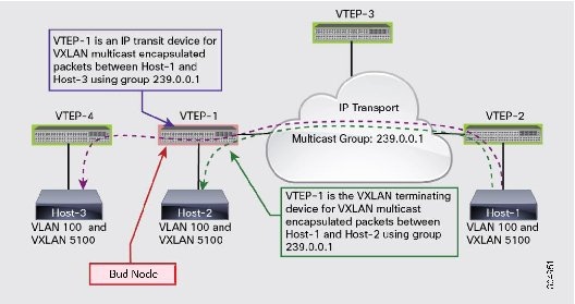
A bud node is a device that is a VXLAN VTEP device and at the same time it is an IP transit device for the same multicast group used for VXLAN VNIs. In the figure, multicast group 239.0.0.1 is used for VXLAN VNIs. For VXLAN multicast encapsulated traffic from Host-1 to Host-2, VTEP-1 performs a multicast reverse-path forwarding (RPF) check in group 239.0.0.1 and then VXLAN decapsulation. For VXLAN multicast encapsulated traffic from Host-1 to Host-3 using the same group 239.0.0.1, VTEP-1 is an IP transit device for the multicast packets. It performs an RPF check and IP forwarding based on the outer IP header that has 239.0.0.1 as the destination. When these two different roles collide on the same device, the device becomes a bud node.
The Cisco Nexus 9000 Series switches provide support for the bud node topology. The application leaf engine (ALE) of the device enables it to be a VXLAN VTEP device and an IP transit device at the same time so the device can become a bud node.
Note |
The bud node topology is not supported when SVI uplinks exist in the configuration. |
Note |
For bud-node topologies, the source IP of the VTEP behind VPC must be in the same subnet as the infra-VLAN. |
A Cisco Nexus Series Switch can be configured to provide a BGP ethernet VPN (EVPN) control plane using a distributed anycast gateway, with Layer 2 and Layer 3 VxLAN overlay networks.
For a data center network, a BGP EVPN control plane provides:
Flexible workload placement that is not restricted with physical topology of the data center network.
Virtual machines may be placed anywhere in the data center, without considerations of physical boundaries of racks.
Optimal east-west traffic between servers within and across data centers
East west traffic between servers/virtual machines is achieved by most specific routing at the first hop router, where the first hop routing is done at the access layer. Host routes must be exchanged to ensure most specific routing to and from servers/hosts. Virtual machine mobility is supported via detecting of virtual machine attachment and signaling new location to rest of the network.
Eliminate or reduce flooding in the data center.
Flooding is reduced by distributing MAC reachability information via BGP EVPN to optimize flooding relating to L2 unknown unicast traffic. Optimization of reducing broadcasts associated with ARP/IPv6 Neighbor solicitation is achieved via distributing the necessary information via BGP EVPN and caching it at the access switches, address solicitation request can then locally responded without sending a broadcast.
Standards based control plane that can be deployed independent of a specific fabric controller.
The BGP EVPN control plane approach provides:
IP reachability information for the tunnel endpoints associated with a segment and the hosts behind a specific tunnel endpoint.
Distribution of host MAC reachability to reduce/eliminate unknown unicast flooding.
Distribution of host IP/MAC bindings to provide local ARP suppression.
Host mobility.
A single address family (BGP EVPN) to distribute both L2 and L3 route reachability information.
Segmentation of Layer 2 and Layer 3 traffic
Traffic segmentation is achieved with using VxLAN encapsulation, where VNI acts as segment identifier.
Note |
Distributed anycast gateway refers to the use of anycast gateway addressing and an overlay network to provide a distributed control plane that governs the forwarding of frames within and across a L3 core network. The distributed anycast gateway functionality will be used to facilitate flexible workload placement, and optimal traffic across the L3 core network. The overlay network that will be used is based on VXLAN. |
 Feedback