Cisco Nexus 9504 NX-OS Mode Switch Hardware Installation Guide
Bias-Free Language
The documentation set for this product strives to use bias-free language. For the purposes of this documentation set, bias-free is defined as language that does not imply discrimination based on age, disability, gender, racial identity, ethnic identity, sexual orientation, socioeconomic status, and intersectionality. Exceptions may be present in the documentation due to language that is hardcoded in the user interfaces of the product software, language used based on RFP documentation, or language that is used by a referenced third-party product. Learn more about how Cisco is using Inclusive Language.
- Updated:
- June 27, 2014
Chapter: Replacing or Installing Modules, Fan Trays, and Power Supplies
Replacing or Installing Modules, Fan Trays, and Power Supplies
- Preventing Electrostatic Damage
- Installing or Replacing a Supervisor Module
- Installing or Replacing a System Controller Module
- Installing or Replacing an I/O Module
- Replacing a Fan Tray
- Replacing a Fabric Module
- Installing a 3-kW AC Power Supply
Preventing Electrostatic Damage
To prevent electrostatic damage (ESD) to electronic components, which include but are not limited to switch modules, that you handle, you must be sure that you are grounded while handling electronic components.
The switch must be connected to the facility earth ground.
Installing or Replacing a Supervisor Module
The switch can operate with one or two supervisor modules installed in the chassis. If there are two supervisor modules, you can remove the standby supervisor and replace it with another supervisor of the same type as the installed supervisor (both must be either supervisor A modules or both must be supervisor B modules—do not mix supervisor types in the same chassis). If you start to remove the active supervisor, the switch automatically makes the other supervisor active and makes the module that you are removing the standby supervisor. If the switch has only one installed supervisor module, you can install the new supervisor in the empty supervisor slot during operations.
 Warning | Statement 1029—Blank Faceplates and Cover Panels Blank faceplates and cover panels serve three important functions: they prevent exposure to hazardous voltages and currents inside the chassis; they contain electromagnetic interference (EMI) that might disrupt other equipment; and they direct the flow of cooling air through the chassis. Do not operate the system unless all cards, faceplates, front covers, and rear covers are in place. |
Warning | Statement 1034—Backplane Voltage Hazardous voltage or energy is present on the backplane when the system is operating. Use caution when servicing |
Installing or Replacing a System Controller Module
The switch can operate with one or two system controller modules installed in the chassis. You can replace one system controller module while there is another one installed in the chassis.
Warning | Statement 1029—Blank Faceplates and Cover Panels Blank faceplates and cover panels serve three important functions: they prevent exposure to hazardous voltages and currents inside the chassis; they contain electromagnetic interference (EMI) that might disrupt other equipment; and they direct the flow of cooling air through the chassis. Do not operate the system unless all cards, faceplates, front covers, and rear covers are in place. |
Warning | Statement 1034—Backplane Voltage Hazardous voltage or energy is present on the backplane when the system is operating. Use caution when servicing |
| Step 1 | Open the
packaging for the new system controller module and inspect the module for
damage.
If the module is damaged, alert the Technical Assistance Center (TAC). | ||||||||
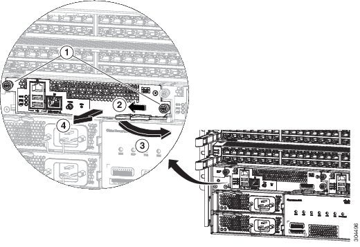
| Step 2 | If you are installing the module in an empty slot, remove the blank module that is already in that slot by unscrewing its captive screw and pulling it out of the slot. Go to Step 4. | ||||||||
| Step 3 | If you are
replacing a module that is currently in the chassis, remove the existing module
from the chassis by following these steps:
| ||||||||
| Step 4 | To install the
new module, follow these steps:
|
Installing or Replacing an I/O Module
The switch can operate with one or more I/O modules installed in the chassis. If there is at least one I/O module installed and operating in the chassis, you can replace another I/O module or install a new I/O module in an empty I/O module slot.
Warning | Statement 1029—Blank Faceplates and Cover Panels Blank faceplates and cover panels serve three important functions: they prevent exposure to hazardous voltages and currents inside the chassis; they contain electromagnetic interference (EMI) that might disrupt other equipment; and they direct the flow of cooling air through the chassis. Do not operate the system unless all cards, faceplates, front covers, and rear covers are in place. |
Warning | Statement 1034—Backplane Voltage Hazardous voltage or energy is present on the backplane when the system is operating. Use caution when servicing |
Warning | Statement 1051—Laser Radiation Invisible laser radiation may be emitted from disconnected fibers or connectors. Do not stare into beams or view directly with optical instruments. |
| Step 1 | Open the
packaging for the new I/O module and inspect the module for damage.
If the module is damaged, contact the Technical Assistance Center (TAC). | ||||||||
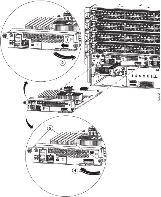
| Step 2 | If you are installing the module in an empty slot, remove the blank module that is already in that slot by unscrewing its two captive screws and pulling it out of the slot. Go to Step 4. | ||||||||
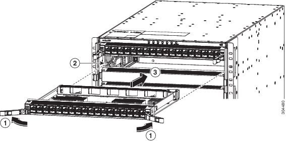
| Step 3 | If you are
replacing a module that is currently in the chassis, remove the existing module
from the chassis by following these steps:
| ||||||||
| Step 4 | To install the
new module, follow these steps:
|
Replacing a Fan Tray
You can remove a fan tray to either replace it with another fan tray or to replace a fabric modules located behind it.
The switch uses three fan trays but it can operate with two fan trays while you replace one or remove one to replace one of the fabric modules behind the fan tray. When you remove one fan tray, the other fan trays speed up their fans to maintain the designed airflow.
 Note | If you cannot replace a fan tray within three minutes, we recommend that you leave it in the chassis until you are ready to replace it. |
Note | If you remove more than one fan tray at a time during operations, the switch allows up to two minutes of operations before shutting down unless you replace extra missing fan trays within that time. If the switch senses an overtemperature condition when multiple fan trays are removed, the shutdown can occur in less than two minutes. |
To replace a fan tray, you must perform the following functions:
-
Remove the fan tray as explained in Removing a Fan Tray.
-
If you need to replace a fabric module behind the removed fan tray, see Replacing a Fabric Module
-
Install a fan tray as explained in Installing a Fan Tray.
Warning | Statement 1034—Backplane Voltage Hazardous voltage or energy is present on the backplane when the system is operating. Use caution when servicing |
Removing a Fan Tray
Remove only one fan tray at a time during switch operations. If you remove more than one fan tray at a time, the switch will shut down within two minutes unless you replace the extra fan trays that you removed within that time.
-
You must wear an electrostatic discharge (ESD) wrist strap or other ESD protective device while handling modules.
-
Prepare an antistatic surface or packing materials for each module that you remove from the chassis.
-
If you are replacing a fan tray, open the packaging for the new fan tray and inspect it for damage. If the module is damaged, contact the Technical Assistance Center (TAC) and wait until you have an undamaged fan tray to install.
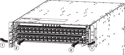
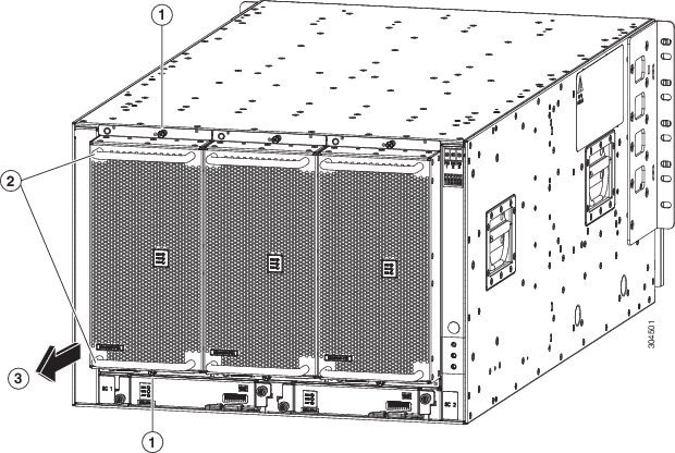
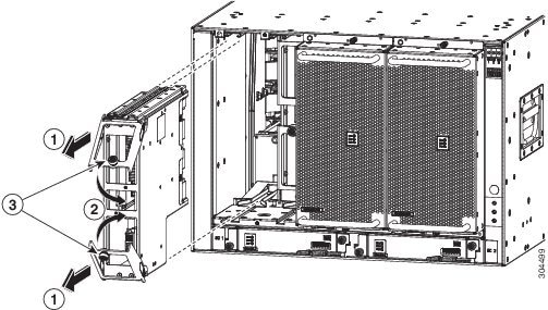
| Step 1 | Unscrew the
four captive screws on the front of the fan tray (one on each corner of the
front of the fan tray) until each screw is free of the chassis (see Callout 1
in the following figure).
| ||||||||
| Step 2 | Hold both handles on the front of the fan tray with both of your hands and pull the fan tray out of the slot. | ||||||||
| Step 3 | Set the fan tray on antistatic material or inside an antistatic bag. |
Installing a Fan Tray
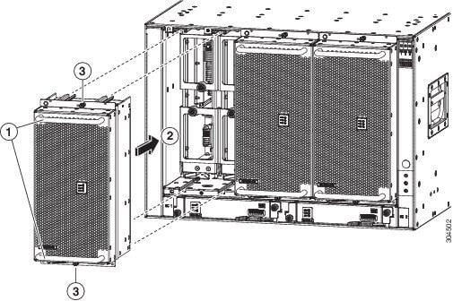
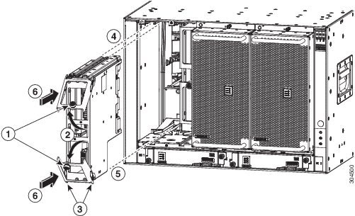
| Step 1 | Use both of your
hands to hold the two handles on the front of the fan tray that you are
installing.
| ||||||||
| Step 2 | Position the fan tray with its rear (the side with the electrical connectors at the opening for the fan tray slot in the chassis. | ||||||||
| Step 3 | Align the two tracks on the top of the fan tray with the two sets of rails at the top of the open fan tray slot in the chassis. | ||||||||
| Step 4 | Slide the fan
tray all the way into the slot until the front of the fan tray touches the
chassis.
Make sure that the four captive screws on the front of the fan tray align with the four screw holes in the chassis. | ||||||||
| Step 5 | Screw in the four captive screws to secure the fan tray to the chassis. Tighten the screws to 8 in-lb (0.9 N·m) of torque. | ||||||||
| Step 6 | Verify that the fan tray STATUS LED turns on and becomes green. |
Replacing a Fabric Module
The switch uses either three or six fabric modules but you can replace a fabric module while others are operating. To replace a fabric module, you must do each of the following:
- Shutdown the fabric module being replaced.
- Remove the fan tray covering the fabric module in the chassis.
- Remove the fabric module.
- Install the new fabric module.
- Reinstall the fan tray over the fabric module.
- Activate the fabric module.
To maintain the designed airflow while you remove the fan tray, the fans in the other fan trays increase their speed. During operations, we recommend that you remove only one fan tray at a time and replace that fan tray within three minutes to avoid the possibility of having the switch overheat and shut down. If you remove more than one fan tray at a time, the switch will shut down if you do not replace the extra missing fan trays within two minutes (the shutdown can occur earlier if an overtemperature condition occurs).
Note | If the switch does not have all of the fabric slots filled, fill them as indicated in the following table and insert blank filler plates in the open slots. If you do not fill the recommended slots with fabric modules, some of the fans will not power up. |
| Number of Fabric Modules | Slots to be Filled |
|---|---|
|
1 (Not allowed) |
N.A. |
|
2 (Not recommended) |
N.A. |
|
3 (Minimum recommended number) |
22, 24, and 26 |
|
4 |
22, 23, 24, and 26 |
|
5 |
21, 22, 23, 24, and 26, or 22, 23, 24, 25, and 26 |
|
6 (Fully populated) |
21, 22, 23, 24, 25, and 26 |
To replace a fabric module, you must perform these operations, which are explained in the topics that follow:
-
Remove the fan tray that covers the fabric module that you are replacing.
-
Shutdown and remove the fabric module.
-
Install the new fabric module.
-
Install the fan tray over the new fabric module.
Warning | Statement 1034—Backplane Voltage Hazardous voltage or energy is present on the backplane when the system is operating. Use caution when servicing |
Removing a Fabric Module
-
You must wear an electrostatic discharge (ESD) wrist strap or other ESD protective device while handling modules.
-
Prepare an antistatic surface or packing materials for each module that you remove from the chassis.
-
You must remove the fan tray that covers the fabric module that you are removing (see t_n95xx_remove_fan_tray.xml.
| Step 1 | If you are
replacing a fabric module, open the packaging for the new module and inspect it
for damage.
If the module is damaged, alert the Technical Assistance Center (TAC) and stop this replacement process until you have an undamaged module to install. | ||||||||||||
| Step 2 | Remove the fan
tray that covers the fabric module by following these steps:
| ||||||||||||
| Step 3 | To prevent a loss of packets during operations, shut down the fabric module as follows: . | ||||||||||||
| Step 4 | Remove the
fabric module that you are replacing by following these steps:
|
What to Do Next
You are ready to install a fabric module into the open slot (see t_n95xx_install_fabric.xml.
Installing a Fabric Module
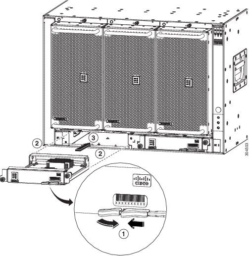
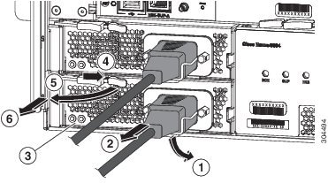
| Step 1 | Place one hand on the front of the module and turn the module 90 degrees so that the electrical connectors are on the bottom. | ||||||||||||
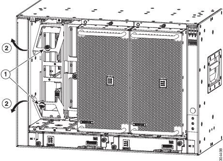
| Step 2 | Unscrew the
two captive screws (one on each ejector handle) and rotate the ejector handles
away from the chassis (see Callouts 1 and 2 in the following figure). Be sure
that the locking posts on the top and bottom of the chassis (see Callout 3)
rotate into the module so that the module can slide fully into the slot.
| ||||||||||||
| Step 3 | Fit the guide rails on the top of the module into the track on the top of the slot and make sure that the guide bar on the bottom of the module goes into the module guide at the bottom of the slot. | ||||||||||||
| Step 4 | Slide the module all the way into the slot. | ||||||||||||
| Step 5 | Rotate both ejector levers to the front of the chassis and be sure that the module is locked to the top and bottom of the slot. | ||||||||||||
| Step 6 | Screw in the captive screw on each of the two levers so that each lever is locked in place on the module. Tighten each screw to 8 in-lb (0.9 N·m) of torque. | ||||||||||||
| Step 7 | Power up the
fabric module as follows:
| ||||||||||||
| Step 8 | Replace the
fan module over the replaced fabric module by following these steps:
|
What to Do Next
You are ready to reinstall the fan tray that covers the newly installed fabric module.
Installing a 3-kW AC Power Supply
The number of 3-kW power supplies that you install depends on the power requirements of the switch and the power mode that you are using. To determine the power requirements of the switch, see the Power Requirements section.
If you are using only one power source for combined mode or power-supply (n+1) redundancy mode, you can install the power supplies in any of the power supply slots on the chassis. If you are using two power sources for input-source (grid or n+n) redundancy mode, you must connect the power supplies in slots 1 and 2 to one power source and the power supplies in slots 3 and 4 to the other power source. With input-source redundancy mode, divide the power supplies evenly between the first four slots and the last four slots so that the amount of redundant power for the switch equals the amount of available power for the switch.
Warning | Statement 1034—Backplane Voltage Hazardous voltage or energy is present on the backplane when the system is operating. Use caution when servicing |
Warning | Statement 1029—Blank Faceplates and Cover Panels Blank faceplates and cover panels serve three important functions: they prevent exposure to hazardous voltages and currents inside the chassis; they contain electromagnetic interference (EMI) that might disrupt other equipment; and they direct the flow of cooling air through the chassis. Do not operate the system unless all cards, faceplates, front covers, and rear covers are in place. |
-
The AC power source must be installed within reach of the power cables.
-
The AC power source must meet the power specifications required by the switch.
-
There are one or two AC power sources available. If using input-source (grid or n+n) redundancy, there must be two power sources available. Otherwise, only one power source is required.
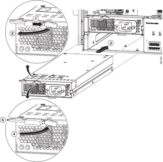
| Step 1 | Open the
packaging for the new 3-kW AC power supply and inspect the module for damage.
If the module is damaged, contact the Technical Assistance Center (TAC). | ||||||||||||
| Step 2 | If you are installing the module in an empty slot, remove the blank filler plate that is already in that slot by unscrewing its captive screw and pulling it out of the slot. If you are using the combined power mode (no power redundancy) or power-supply (n+1) redundancy, you can use any power supply slot in the chassis. If you are using input-source (grid or n+n) redundancy mode, you must be sure that you are inserting the power supply in a slot used for the desired power supply (the power supplies in slots 1 and 2 must be connected to one power source and the power supplies in slots 3 and 4 must be connected to the other power source). Go to Step 4. | ||||||||||||
| Step 3 | If you are
replacing a power supply that is currently in the chassis, remove the existing
module from the chassis by following these steps:
| ||||||||||||
| Step 4 | To install the
new power supply, follow these steps:
|
 Feedback