Cisco Nexus 9504 NX-OS Mode Switch Hardware Installation Guide
Bias-Free Language
The documentation set for this product strives to use bias-free language. For the purposes of this documentation set, bias-free is defined as language that does not imply discrimination based on age, disability, gender, racial identity, ethnic identity, sexual orientation, socioeconomic status, and intersectionality. Exceptions may be present in the documentation due to language that is hardcoded in the user interfaces of the product software, language used based on RFP documentation, or language that is used by a referenced third-party product. Learn more about how Cisco is using Inclusive Language.
- Updated:
- June 27, 2014
Chapter: Installing a Chassis
Installing a Chassis
- Installing a Rack or Cabinet
- Unpacking and Inspecting a New Switch
- Installing the Bottom-Support Rails
- Installing a Chassis in a Rack or Cabinet
- Grounding the Chassis
- Connecting the Switch to an AC Power Source
Installing a Rack or Cabinet
Before you install the switch, you must install a standard four-post, 19-inch (48.3 cm) EIA data center rack (or a cabinet that contains such a rack) that meets the requirements listed in Rack and Cabinet Requirements.
 Warning | Statement 1048—Rack Stabilization Stability hazard. The rack stabilizing mechanism must be in place, or the rack must be bolted to the floor before you slide the unit out for servicing. Failure to stabilize the rack can cause the rack to tip over. |
Warning | Statement 1018—Supply Circuit Take care when connecting units to the supply circuit so that wiring is not overloaded. |
Unpacking and Inspecting a New Switch
Before you install a new chassis, you need to unpack and inspect it to be sure that you have all the items that you ordered and verify that the switch was not damaged during shipment.
 Caution | When you handle the chassis or its components, you must follow ESD protocol at all times to prevent ESD damage. This protocol includes but is not limited to wearing an ESD wrist strap that you connect to the earth ground. |
 Tip | Do not discard the shipping container when you unpack the switch. Flatten the shipping cartons and store them with the pallet used for the system. If you need to move or ship the system in the future, you will need these containers. |
| Step 1 | Compare the
shipment to the equipment list that is provided by your customer service
representative and verify that you have received all of the ordered items. The
shipment should include boxes for the following:
|
| Step 2 | Check the contents of each box for damage. |
| Step 3 | If you notice any discrepancies or damage, send the following information to your customer service representative by email: |
Installing the Bottom-Support Rails
The bottom-support rails support the weight of the switch chassis in the rack or cabinet. To maximize the stability of the rack, you must attach these rails at the lowest possible rack unit (RU).
Warning | Statement 1006—Chassis Warning for Rack-Mounting and Servicing To prevent bodily injury when mounting or servicing this unit in a rack, you must take special precautions to ensure that the system remains stable. The following guidelines are provided to ensure your safety:
|
Before you can install the bottom support rails for the chassis, you must do the following:
-
Verify that a four-post rack or cabinet is installed and secured to the concrete subfloor (see Install a four-post rack and secure it to the concrete subfloor.).
-
If any other devices are stored in rack or cabinet, verify that they are located below where you plan to install the switch. Also, verify that lighter devices in the same rack are located above where you plan to install this switch.
-
Verify that the bottom-support rails kit is included in the switch accessory kit (see Unpack and inspect the chassis shipment for completeness and damage).
| Step 1 | Position one of
the two adjustable bottom-support rails at the lowest possible RU in the rack
or cabinet and adjust the length of each rail so that it stretches from the
outer edges of the front and rear vertical mounting rails on the rack. Be sure
there is at least
7.1
RU (12.4 in [31.6 cm]) of vertical space above the
rails to install the chassis (see the following figure).
You can expand the rail so that its mounting brackets are spaced between 24 to 32 inches (61.0 to 81.3 cm). 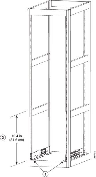
| ||||||
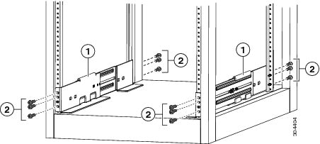
| Step 2 | Attach the
bottom-support rail to the rack or cabinet using a Phillips torque screwdriver
on three M6 x 19 mm or 12-24 x 3/4 inch screws for each end of the rail (using
a total of 6 screws for the rail as shown in the following figure) and tighten
each screw to 40 in-lbs (4.5 N.m) of torque.
| ||||||
| Step 3 | Repeat Steps 1
and 2 to attach the other bottom-support rail to the rack.
|
What to Do Next
When the bottom-support rails are installed at the lowest possible RU and are level, you are ready to install the chassis in the rack or cabinet.
Installing a Chassis in a Rack or Cabinet
Verify each of the following:
-
The chassis shipment is complete and undamaged.
-
A four-post rack or cabinet is installed and secured to the concrete subfloor.
WarningStatement 1048—Rack Stabilization
Stability hazard. The rack stabilizing mechanism must be in place, or the rack must be bolted to the floor before you slide the unit out for servicing. Failure to stabilize the rack can cause the rack to tip over.
-
The bottom-support rails have been attached to the lowest possible RU in the rack or cabinet and there is 7.1 RU (12.4 in [31.6 cm]) of space above the rails to install the chassis.
-
If there are other devices in the rack, ensure that the heavier devices are installed below where you are going to install the chassis.
-
The data center ground is accessible where you are installing the chassis.
-
You have the following tools and equipment:
-
Mechanical lift capable of lifting the full weight of the chassis (a maximum of 255 pounds [116 kg]) and its installed modules
-
Phillips-head torque screwdriver
-
Bottom-support rails kit (shipped with the accessory kit)
Part of this kit has already been used to install the bottom-support rails. You should still have at least 12 12-24 x 3/4-inch or M6 x 19 mm Phillips screws, which are required for attaching the chassis to the rack.
-
 Note | You should also have at least two persons to push the chassis and one person to guide the chassis when you slide it into the rack. |
Warning | Statement 1006—Chassis Warning for Rack-Mounting and Servicing To prevent bodily injury when mounting or servicing this unit in a rack, you must take special precautions to ensure that the system remains stable. The following guidelines are provided to ensure your safety:
|
Warning | Statement 1074—Comply with Local and National Electrical Codes Installation of the equipment must comply with local and national electrical codes. |
| Step 1 | If you need to
make the chassis as light as possible for moving, remove the following modules
and place them where their connectors will not be damaged:
| ||||||||||
| Step 2 | Load the
chassis onto a mechanical lift as follows:
| ||||||||||
| Step 3 | Use the
mechanical lift to move and align the rear of the chassis to the front of the
four-post rack or cabinet.
Make sure that the bottom of the chassis is elevated to the height of the bottom-support rails or no more than 1/4 inch (0.6 cm) above the bracket. | ||||||||||
| Step 4 | Push the chassis
halfway onto the rack or cabinet.
Use at least two persons to push the chassis onto the bottom-support rails and one person to guide the chassis down the center of the rails. Push the lower half of the front side of the chassis so that the back side enters the rack first, and push until the chassis is halfway onto the rack (see the following figure). Ensure that the chassis does not get caught on any of the expansion edges of the bottom-support rail. 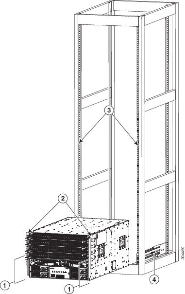
| ||||||||||
| Step 5 | If the
mechanical lift is raised above the height of the bottom-support rails, gently
lower it to the level of the rails or no more than 1/4 inch (0.6 cm) below the
rails.
This action helps to prevent the bottom of the chassis from getting caught on the expansion edges of the bottom-support rail. | ||||||||||
| Step 6 | Push the chassis all the way onto the rack so that the vertical mounting brackets on the front of the chassis come in contact with the vertical mounting rails on the rack. | ||||||||||
| Step 7 | Use six M6 x 19 mm or 24 x 3/4-inch screws to attach each of the two chassis vertical mounting brackets to the two rack vertical mounting rails (total of 12 screws). |
What to Do Next
After you have secured the chassis to the rack, you can connect the chassis to the data center ground.
Grounding the Chassis
The switch is grounded when you connect the chassis and the power supplies to the earth ground in the following ways:
-
You connect the chassis (at its grounding pad) to either the data center ground or to a fully-bonded and grounded rack.
Note
The chassis ground connection is active even when the AC power cables are not connected to the system.
-
You connect the AC power supplies to the earth ground automatically when you connect an AC power supply to an AC power source.
Warning | Statement 1046—Installing or Replacing the Unit When installing or replacing the unit, the ground connection must always be made first and disconnected last. |
Before you can ground the chassis, you must have a connection to the earth ground for the data center building. If you installed the switch chassis into a bonded rack (see the rack manufacturer's instructions for more information) that now has a connection to the data center earth ground, you can ground the chassis by connecting its grounding pad to the rack. Otherwise, you must connect the chassis grounding pad directly to the data center ground.
To connect the switch chassis to the data center ground, you need the following tools and materials:
-
Grounding lug—A two-holed standard barrel lug that supports up to 6 AWG wire. This lug is supplied with the accessory kit.
-
Grounding screws—Two M4 x 8 mm (metric) pan-head screws. These screws are shipped with the accessory kit.
-
Grounding wire—Not supplied with the accessory kit. This wire should be sized to meet local and national installation requirements. Depending on the power supply and system, a 12 AWG to 6 AWG copper conductor is required for U.S. installations. We recommend that you use commercially available 6 AWG wire. The length of the grounding wire depends on the proximity of the switch to proper grounding facilities.
-
Number 1 Phillips-head torque screwdriver.
-
Crimping tool to crimp the grounding wire to the grounding lug.
-
Wire-stripping tool to remove the insulation from the grounding wire.
| Step 1 | Use a wire-stripping tool to remove approximately 0.75 inch (19 mm) of the covering from the end of the grounding wire. | ||||||||
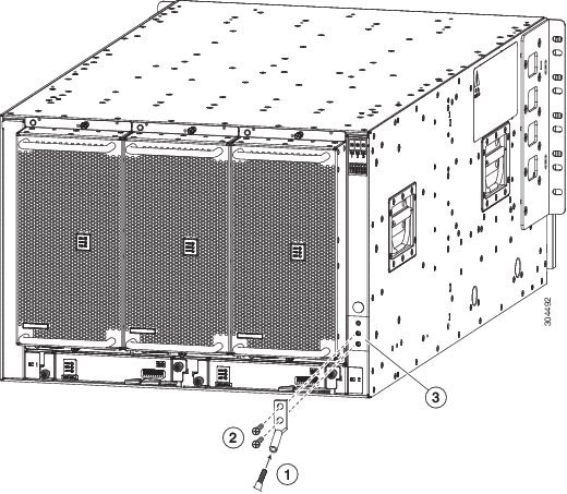
| Step 2 | Insert the
stripped end of the grounding wire into the open end of the grounding lug, and
use a crimping tool to crimp the lug to the wire (see Callout 2 in the
following figure). Verify that the ground wire is securely attached to the
grounding lug by attempting to pull the wire out of the crimped lug.
| ||||||||
| Step 3 | Secure the grounding lug to the chassis grounding pad with two M4 screws (see Callouts 1 and 3 in the previous figure), and tighten the screws to 12 in-lb (1.36 N·m) of torque. | ||||||||
| Step 4 | Prepare the other end of the grounding wire and connect it to an appropriate grounding point in your site to ensure an adequate earth ground for the switch. If the rack is fully bonded and grounded, connect the grounding wire as explained in the documentation provided by the vendor for the rack. |
Connecting the Switch to an AC Power Source
You turn on the switch as soon as you connect its AC power supplies to one or two AC power sources.
Warning | Statement 1004—Installation Instructions Read the installation instructions before connecting the system to the power source. |
Warning | Statement 1018—Supply Circuit Take care when connecting units to the supply circuit so that wiring is not overloaded. |
Before you can turn on the switch, you must ensure the following:
-
The switch has enough power supplies to output the power required for all of the modules installed in the switch. Depending on the power mode that you use for the switch, you need to consider the following:
-
For combined power mode (no power redundancy), there must be enough power supplies to power all of the modules in the chassis (no extra power supplies are needed for redundancy). A maximum of two power supplies are needed.
-
For power supply redundancy (n+1) mode, there must be enough power supplies to power all of the modules in the chassis and there must be one extra power supply to provide redundancy if one power supply goes down or is replaced. The maximum number of power supplies needed is the number used for combined power mode plus one (n+1) for redundancy.
-
For input-source redundancy (n+n) mode, there must be two equal sets of power supplies, each of which can power all of the modules in the chassis and is connected to a separate power source. If one power source goes down, the power supplies connected to the other power source can power the switch. The maximum number of power supplies is the number of power supplies required for combined power plus the same number of power supplies (n+n) for redundancy.
-
-
The power supplies are installed in the appropriate chassis slots as follows:
What to Do Next
When the power supplies are operating and the switch is fully powered, you are ready to connect the switch to the network.
 Feedback