Cisco Nexus 9504 NX-OS Mode Switch Hardware Installation Guide
Bias-Free Language
The documentation set for this product strives to use bias-free language. For the purposes of this documentation set, bias-free is defined as language that does not imply discrimination based on age, disability, gender, racial identity, ethnic identity, sexual orientation, socioeconomic status, and intersectionality. Exceptions may be present in the documentation due to language that is hardcoded in the user interfaces of the product software, language used based on RFP documentation, or language that is used by a referenced third-party product. Learn more about how Cisco is using Inclusive Language.
- Updated:
- June 27, 2014
Chapter: Overview
Contents
Overview
Overview
The Cisco Nexus 9504 switch chassis (N9K-C9504) holds the following components:
-
Supervisor modules (one or two supervisor modules of the same type)
-
System controllers (up to two system controller modules) (N9K-SC-A)
-
I/O modules (up to four I/O modules)
-
48-port 1-/10-Gigabit SFP+ plus 4-port 40-Gigabit QSFP+ I/O module (N9K-X9464PX)
-
48-port 1-/10-GBASE-T plus 4-port 40-Gigabit QSFP+ I/O module (N9K-X9464TX)
-
48-port 1-/10-GBASE-T plus 4-port QSFP+ I/O module (N9K-X9564TX)
-
48-port 1-/10-Gigabit SFP+ plus 4-port QSFP+ I/O module (N9K-X9564PX)
-
36-port 40-Gigabit QSFP+ aggregation (non-blocking) I/O module (N9K-X9636PQ)
-
36-port 40-Gigabit QSFP+ I/O module (N9K-X9536PQ)
-
32-port 40-Gigabit QSFP+ I/O module (N9K-X9432PQ)
-
-
Fabric modules (up to six fabric modules behind the fan trays) (N9K-C9504-FM)
-
Fan trays (three) (N9K-C9504-FAN)
-
AC power supplies (up to four 3-kW AC power supplies) (N9K-PAC-3000W-B)
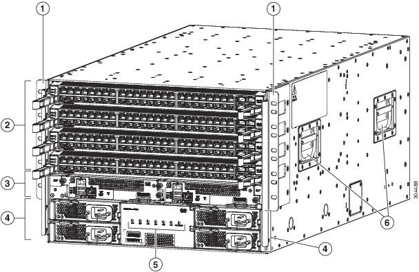
The following figure shows the hardware features seen from the front of the chassis.
|
1 |
Two vertical mounting brackets used to mount the chassis onto a rack |
4 |
3-kW AC power supplies (up to two without power redundancy or up to four with power redundancy) in slots PS 1 to PS 4 |
|
2 |
I/O modules (up to four) in slots LC 1 to LC 4 |
5 |
Chassis LEDs |
|
3 |
Supervisor modules (one or two) in slots SUP 1 and SUP 2 (identified in CLI output as Modules 27 and 28) |
6 |
Chassis handles (used only for positioning the chassis on the bottom support rails—do not use these handles for lifting the chassis) |
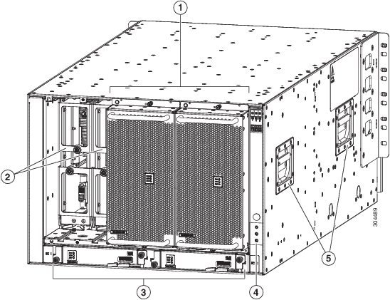
The following figure shows the hardware features seen from the rear of the chassis (one fan tray has been removed to show the fabric modules behind the fan trays).
|
1 |
Fan trays (three—one not shown in order to display the fabric modules located behind the fan trays) in slots slots FAN 1 to FAN 3 (identified in CLI output as Modules 41 to 43) |
4 |
Grounding pad |
|
2 |
Fabric modules (up to six—up to two behind each fan tray) in slots FM 1 to FM 6 (identified in CLI output as Modules 21 to 26) |
5 |
Chassis handles (used only for positioning the chassis on the bottom support rails—do not use these handles for lifting the filled chassis) |
|
3 |
System controllers (two) in slots SC 1 and SC 2 (identified in CLI output as Modules 29 and 30) |