Cisco Nexus Cloud Services Platform Hardware Installation Guide
Bias-Free Language
The documentation set for this product strives to use bias-free language. For the purposes of this documentation set, bias-free is defined as language that does not imply discrimination based on age, disability, gender, racial identity, ethnic identity, sexual orientation, socioeconomic status, and intersectionality. Exceptions may be present in the documentation due to language that is hardcoded in the user interfaces of the product software, language used based on RFP documentation, or language that is used by a referenced third-party product. Learn more about how Cisco is using Inclusive Language.
- Updated:
- June 23, 2014
Chapter: Installing a Cisco Nexus Cloud Services Platform Without CIMC
- Preparing for Installation
- Hardware Installation Process
- Unpacking the Cisco Nexus Cloud Services Platform
- Installing the Cisco Nexus Cloud Services Platform Into a Rack
- Connecting the Power Cable
- Connecting to Upstream Switches
Installing a Cisco Nexus Cloud Services Platform Without CIMC
This chapter describes how to install a Cisco Nexus Cloud Services Platform and includes the following sections:
- Preparing for Installation
- Hardware Installation Process
- Unpacking the Cisco Nexus Cloud Services Platform
- Installing the Cisco Nexus Cloud Services Platform Into a Rack
- Connecting the Power Cable
- Connecting to Upstream Switches
- Configuring Terminal Server Access for the Cisco Nexus Cloud Services Platform
- Powering On a Cisco Nexus Cloud Services Platform Appliance
- Connecting to the Cloud Services Platform CLI
- Where to Go Next

Note If you want to configure CIMC and use serial over LAN (SoL) instead of a terminal server, see the “Installing a Cisco Nexus Cloud Services Platform with CIMC” section.
Note Before you install, operate, or service the system, see the Regulatory Compliance and Safety Information for the Cisco Nexus Cloud Services Platform document for important safety information.

Warning IMPORTANT SAFETY INSTRUCTIONS
This warning symbol means danger. You are in a situation that could cause bodily injury. Before you work on any equipment, be aware of the hazards involved with electrical circuitry and be familiar with standard practices for preventing accidents. Use the statement number provided at the end of each warning to locate its translation in the translated safety warnings that accompanied this device.
Statement 1071
Warning Only trained and qualified personnel must be allowed to install, replace, or service this equipment. Statement 1030
Warning To prevent bodily injury when mounting or servicing this unit in a rack, you must take special precautions to make sure the system remains stable. The following guidelines are provided to ensure your safety:
This unit should be mounted at the bottom of the rack if it is the only unit in the rack.
When mounting this unit in a partially filled rack, load the rack from the bottom to the top with the heaviest component at the bottom of the rack.
If the rack is provided with stabilizing devices, install the stabilizers before mounting or servicing the unit in the rack.
Statement 1006
Preparing for Installation
This section includes the following topics:
Installation Guidelines
When installing the appliance, follow these guidelines:
- If you are installing a pair of redundant Cisco Nexus 1110s, you must install them in pairs. The first Cisco Nexus 1110 installed has the primary role and the second Cisco Nexus 1110 installed has the secondary role. A Cisco Nexus1010-X and a Cisco Nexus1010 can form an HA pair.
- Make sure there is adequate space around the appliance to allow for servicing and for adequate airflow. The airflow in this appliance is from front to back.
- Make sure the air-conditioning meets the thermal requirements listed in Appendix A, “Technical Specifications.”
- Make sure the cabinet or rack meets the requirements listed in the “Rack Requirements” section.
- Make sure the site power meets the power requirements listed in Appendix A, “Technical Specifications.” If available, you can use an uninterruptible power supply (UPS) to protect against power failures.
- Make sure circuits are sized according to local and national codes. For North America, the power supply requires a 15-Amp circuit.
- Make sure the system date and time match the actual date (UST) in the BIOS menu whenever you install Cisco Nexus Cloud Services Platform.
Warning The plug-socket combination must be accessible at all times, because it serves as the main disconnecting device.
Statement 1019

Rack Requirements
This section provides the requirements for the standard open racks, assuming an external ambient air temperature range of 32 to 95°F (0 to 35°C).
The rack must be of the following type:
- Standard 19-inch (48.3-cm) four-post EIA rack, with mounting posts that conform to English universal hole spacing per section 1 of ANSI/EIA-310-D-1992.
- The rack post holes must be square when you use the supplied attachment hardware.
-
The minimum vertical rack space per appliance must be one rack unit (RU), equal to 1.75 inches
(4.45 cm).
Hardware Installation Process
Use the following procedures in this section to install the Cisco Nexus 1110 hardware and connect to your network without configuring the CIMC interface.
Step 1![]() Unpacking the Cisco Nexus Cloud Services Platform
Unpacking the Cisco Nexus Cloud Services Platform
Step 2![]() Installing the Cisco Nexus Cloud Services Platform Into a Rack
Installing the Cisco Nexus Cloud Services Platform Into a Rack
Step 3![]() Connecting the Power Cable
Connecting the Power Cable
Step 4![]() Connecting to Upstream Switches
Connecting to Upstream Switches
Step 5![]() Configuring Terminal Server Access for the Cisco Nexus Cloud Services Platform
Configuring Terminal Server Access for the Cisco Nexus Cloud Services Platform
Step 6![]() Powering On a Cisco Nexus Cloud Services Platform Appliance
Powering On a Cisco Nexus Cloud Services Platform Appliance
Step 7![]() Connecting to the Cloud Services Platform CLI
Connecting to the Cloud Services Platform CLI
Step 8![]() Where to Go Next
Where to Go Next
Unpacking the Cisco Nexus Cloud Services Platform
This section includes the following topics:
Shipping Box Contents
The following is a list of the shipping box contents.
- Cisco Nexus Cloud Services Platform
- AC power cord
- RJ-45 cable
- DB-9–to–RJ-45 adapter
- Documentation
- KVM cable
- Slide-rail assembly
- Length-adjustment bracket
- Cable management arm (CMA)
Note The chassis is thoroughly inspected before shipment. If equipment is damaged or if any items are missing, contact your customer service representative immediately.
Inspecting the Contents
Use this procedure to inspect the shipment.
Step 1![]() Remove the appliance from its cardboard container—save all packaging material.
Remove the appliance from its cardboard container—save all packaging material.
Step 2![]() Compare the shipment to the equipment list provided by your customer service representative and verify that you have all items. Verify the shipping box contents against the list in the “Shipping Box Contents” section.
Compare the shipment to the equipment list provided by your customer service representative and verify that you have all items. Verify the shipping box contents against the list in the “Shipping Box Contents” section.
Step 3![]() Check all equipment for damage.
Check all equipment for damage.
Step 4![]() Report discrepancies in equipment contents or damage to your customer service representative. Have the following information ready:
Report discrepancies in equipment contents or damage to your customer service representative. Have the following information ready:
- Invoice number of shipper (see the packing slip)
- Model and serial number of the damaged unit
- Description of damage
- Effect of damage on the installation
Step 5![]() You have completed this procedure. Continue with the Installing the Cisco Nexus Cloud Services Platform Into a Rack.
You have completed this procedure. Continue with the Installing the Cisco Nexus Cloud Services Platform Into a Rack.
Installing the Cisco Nexus Cloud Services Platform Into a Rack
Use this procedure to install the Cisco Nexus Cloud Services Platform into a rack.
BEFORE YOU BEGIN
Before beginning this procedure, you must know or do the following:
DETAILED STEPS
Step 1![]() Install the slide rails into the rack:
Install the slide rails into the rack:
a.![]() Align the slide-rail assembly inside the rack posts with the length-adjustment bracket toward the rear of the rack.
Align the slide-rail assembly inside the rack posts with the length-adjustment bracket toward the rear of the rack.
Note Install the slide-rail assembly that has the plastic retaining clip labeled “Push” onto the left rack post if you plan to install the cable management arm (CMA).
b.![]() Compress the length-adjustment bracket until the mounting pegs and locking clips on the slide-rail assembly engage the desired rack holes on the front and rear rack posts. (see Figure 2-1).Make sure the slide rail is level from front to rear.
Compress the length-adjustment bracket until the mounting pegs and locking clips on the slide-rail assembly engage the desired rack holes on the front and rear rack posts. (see Figure 2-1).Make sure the slide rail is level from front to rear.
Figure 2-1 Attaching a Slide-Rail Assembly

c.![]() Attach the second slide-rail assembly to the opposite side of the rack.
Attach the second slide-rail assembly to the opposite side of the rack.
d.![]() Make sure the two slide-rail assemblies are level and at the same height with each other.
Make sure the two slide-rail assemblies are level and at the same height with each other.
e.![]() Pull the inner slide rails on each assembly out toward the rack front until they hit the internal stops and lock in place.
Pull the inner slide rails on each assembly out toward the rack front until they hit the internal stops and lock in place.
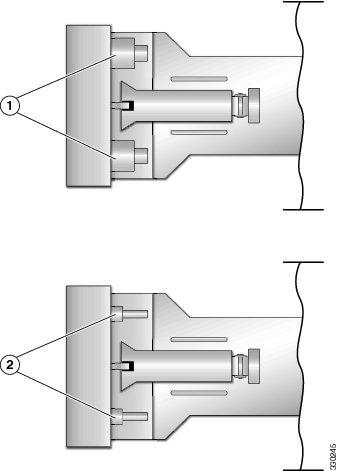
Note The mounting pegs that protrude through the rack-post holes are designed to fit round or square #12-24 holes, or #10-32 holes when the mounting peg is compressed (see Figure 2-2). If your rack has #10-32 rack-post holes, align the mounting pegs with the holes and then compress the spring-loaded pegs to expose the #10-32 inner peg.
Figure 2-2 Spring-Loaded Mounting Pegs
f.![]() Pull the inner slide rails on each assembly out toward the rack front until they hit the internal stops and lock in place.
Pull the inner slide rails on each assembly out toward the rack front until they hit the internal stops and lock in place.
g.![]() Attach the second slide-rail assembly to the opposite side of the rack. Ensure that the two slide-rail assemblies are level and at the same height with each other.
Attach the second slide-rail assembly to the opposite side of the rack. Ensure that the two slide-rail assemblies are level and at the same height with each other.
h.![]() Pull the inner slide rails on each assembly out toward the rack front until they hit the internal stops and lock in place.
Pull the inner slide rails on each assembly out toward the rack front until they hit the internal stops and lock in place.

Tip You can optionally use the #2 Phillips screws that come with the slide rails to increase stability after installation. These screws can be installed on the front attachment bracket on each assembly, but are not required.
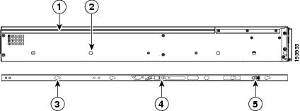
Step 2![]() Attach mounting brackets to the appliance (see Figure 2-3):
Attach mounting brackets to the appliance (see Figure 2-3):
a.![]() Set a mounting bracket (item 3) on the side of the appliance, aligning its keyed holes over the pegs on the appliance (item 2). The plastic installation release clip (item 5) on the bracket should be toward the appliance front.
Set a mounting bracket (item 3) on the side of the appliance, aligning its keyed holes over the pegs on the appliance (item 2). The plastic installation release clip (item 5) on the bracket should be toward the appliance front.
Note Install the mounting bracket that has the CMA flange onto the left side of the appliance, as viewed from the appliance front. Position the CMA flange toward the appliance rear.
b.![]() Push the mounting bracket toward the rear of the appliance until the locking clip clicks over the appliance peg.
Push the mounting bracket toward the rear of the appliance until the locking clip clicks over the appliance peg.
c.![]() Attach the remaining mounting bracket to the opposite side of the appliance.
Attach the remaining mounting bracket to the opposite side of the appliance.
Tip You can optionally use the #1 Phillips screws that come with the slide rails to increase stability after installation. You can install two of these screws on each side of the server to more permanently attach the mounting brackets to each side of the server, but they are not required.
Figure 2-3 Attaching Mounting Brackets to the Appliance
Step 3![]() Insert the appliance into the slide rails:
Insert the appliance into the slide rails:
a.![]() Align the mounting brackets that are attached to the appliance sides with the front of the empty slide rails.
Align the mounting brackets that are attached to the appliance sides with the front of the empty slide rails.
b.![]() Push the appliance into the slide rails until it stops at the internal stops.
Push the appliance into the slide rails until it stops at the internal stops.
c.![]() Push the plastic installation release clip on each mounting bracket toward the appliance rear (see item 5 in Figure 2-3), and then continue pushing the appliance into the rack until its front flanges touch the rack posts.
Push the plastic installation release clip on each mounting bracket toward the appliance rear (see item 5 in Figure 2-3), and then continue pushing the appliance into the rack until its front flanges touch the rack posts.
Step 4![]() Attach the CMA to the rear of the slide rails (see Figure 2-4):
Attach the CMA to the rear of the slide rails (see Figure 2-4):
Note These instructions assume an orientation from the front of the appliance.
a.![]() Slide the plastic clip on the right end of the CMA length-adjustment slider (item 2) into the rear of the right slide rail (item 1) until it clips onto the plastic retaining flange inside the slide rail.
Slide the plastic clip on the right end of the CMA length-adjustment slider (item 2) into the rear of the right slide rail (item 1) until it clips onto the plastic retaining flange inside the slide rail.
b.![]() Expand the CMA length-adjustment slider (item 2) until its left end aligns with the rear of the left slide-rail assembly (item 3).
Expand the CMA length-adjustment slider (item 2) until its left end aligns with the rear of the left slide-rail assembly (item 3).
c.![]() Slide the innermost CMA attachment clip (item 4) into the rear of the left slide rail (item 3) and clip it onto the CMA flange that is on the mounting bracket that is attached to the appliance.
Slide the innermost CMA attachment clip (item 4) into the rear of the left slide rail (item 3) and clip it onto the CMA flange that is on the mounting bracket that is attached to the appliance.
d.![]() Attach the two-hole slotted bracket (item 5) that is on the left end of the CMA length-adjustment slider to the left slide rail (item 3). Fit the two-hole slotted bracket over the two pegs inside the rail.
Attach the two-hole slotted bracket (item 5) that is on the left end of the CMA length-adjustment slider to the left slide rail (item 3). Fit the two-hole slotted bracket over the two pegs inside the rail.
e.![]() Attach the outermost CMA attachment clip (item 6) onto the CMA flange that is on the left rail.
Attach the outermost CMA attachment clip (item 6) onto the CMA flange that is on the left rail.
Figure 2-4 Attaching the Cable Management Arm

Rear of right slide rail (plastic retaining flange is inside the rail) |
|
Two-hole slotted bracket on end of CMA length-adjustment slider |
|
Step 5![]() Continue with the Connecting the Power Cable.
Continue with the Connecting the Power Cable.
Connecting the Power Cable
Use this procedure to connect the Cisco Nexus Cloud Services Platform power supply to an AC power outlet.
BEFORE YOU BEGIN
Before beginning this procedure, you must know or do the following:
- You are familiar with the “Rear Panel Description” section.
- You are familiar with the “Front Panel Description” section.
- You are familiar with the “Front Panel LEDs” section.
- You have the supplied power cord and know the location of the grounded AC power outlet.
- Do not power on the Cisco Nexus Cloud Services Platform at this time.
Warning Blank faceplates and cover panels serve three important functions: they prevent exposure to hazardous voltages and currents inside the chassis; they contain electromagnetic interference (EMI) that might disrupt other equipment; and they direct the flow of cooling air through the chassis. Do not operate the system unless all cards, faceplates, front covers, and rear covers are in place.
Statement 1019
DETAILED STEPS
Step 1![]() Attach the supplied power cord to the power supply on the rear of the Cisco Nexus Cloud Services Platform.
Attach the supplied power cord to the power supply on the rear of the Cisco Nexus Cloud Services Platform.
Step 2![]() Plug the other end of the power cord into a grounded AC power outlet.
Plug the other end of the power cord into a grounded AC power outlet.
Note Do not power on the Cisco Nexus Cloud Services Platform at this time.
Power is supplied to the service processor in standby power mode.
Step 3![]() Verify the Power Status LED on the front panel is blinking green, indicating the Cisco Nexus Cloud Services Platform is in standby power mode.
Verify the Power Status LED on the front panel is blinking green, indicating the Cisco Nexus Cloud Services Platform is in standby power mode.

Step 4![]() You have completed this procedure. Continue with the Connecting to Upstream Switches.
You have completed this procedure. Continue with the Connecting to Upstream Switches.
Connecting to Upstream Switches
This section includes the following topics:
- Information About Network Connections
- Upstream Switch Prerequisites
- Connecting the Uplinks to the Network
Port Numbering
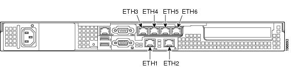
You can connect your Cisco Nexus Cloud Services Platform to the network using the six Gigabit Ethernet RJ-45 ports on the rear panel of the Cisco Nexus Cloud Services Platform shown in Figure 2-5.
Figure 2-5 Rear Panel Gigabit Ethernet Port Numbering
Warning Blank faceplates and cover panels serve three important functions: they prevent exposure to hazardous voltages and currents inside the chassis; they contain electromagnetic interference (EMI) that might disrupt other equipment; and they direct the flow of cooling air through the chassis. Do not operate the system unless all cards, faceplates, front covers, and rear covers are in place.
Statement 1019
Network Traffic Classification
Cisco Nexus Cloud Services Platform network traffic is classified as follows:
For more information about software configuration after connecting to your network, see the most recent version of the Cisco Nexus Cloud Services Platform Software Configuration Guide.
Network Topologies
You can choose one of the following four topologies to funnel traffic into multiple uplinks or shared uplinks by traffic type. Cisco Nexus Cloud Services Platform is installed in high-availability pairs, and the active and standby must be in the same Layer 2 (L2) switching domain.
Upstream Switch Prerequisites
The switch upstream from your Cisco Nexus Cloud Services Platform must meet the following prerequisites before you connect the uplinks.
- Alternate upstream switches must connect to the alternate Ethernet ports on the Cisco Nexus Cloud Services Platform.
–![]() Connect the first upstream switch to Cisco Nexus 1110 Ethernet ports 1, 3, and 5.
Connect the first upstream switch to Cisco Nexus 1110 Ethernet ports 1, 3, and 5.
–![]() Connect the second upstream switch to Cisco Nexus 1110 Ethernet ports 2, 4, and 6.
Connect the second upstream switch to Cisco Nexus 1110 Ethernet ports 2, 4, and 6.
- You must configure the Ethernet ports on the upstream switch in trunk mode.
- The Cisco Nexus Cloud Services Platform does not support native VLAN for the SP(1) version.
- Do not add ports from redundant Cisco Nexus 1110s to the same port channel.
- You must enable LACP mode on the upstream switch.
The following example assigns an Ethernet port to an EtherChannel group, enables EtherChannel mode, or both for a Catalyst 6000 or Catalyst 3000 series switch.
- For detailed information about configuring port channels and LACP, see the documentation for your upstream switch.
- The interfaces in the upstream switch that are in an LACP bond are configured with the same channel ID in active mode. The following example configures an interface with a channel group in active mode for a Catalyst 6000 or Catalyst 3000 series switch.
The following example configures an interface with the adaptive policy for a Catalyst 6000 or Catalyst 3000 series switch.
Connecting the Uplinks to the Network
This section includes procedures for connecting the Cisco Nexus Cloud Services Platform using the Flexible Network Uplink Configuration.
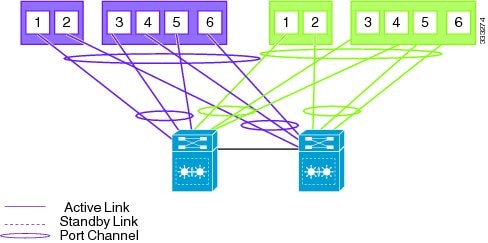
Flexible Network Uplink Configuration
Flexible network configuration offers complete flexibility to connect Cisco Nexus 1110 or Cisco Nexus 1010-X to the network, and allowing flexible deployment of the VSBs on the Cisco Nexus 1110 product family. Flexible configuration thus enables appropriate traffic segregation policies like VSB traffic segregation. The default flexible network uplink configuration is the basic configuration with each physical port acting as an individual uplink. See Figure 2-6. You can then make changes to the default configuration by adding ports to a port channel or by assigning uplinks to a VSB interface.
Note If you need to set up the flex-link mode, but your Cisco Nexus Cloud Services Platform is connected to a pair of switches that is not in VSS, it is recommended that in HA mode, the channel have just 2 members. There will be VSB traffic loss if the switch goes down. Recommended LACP for this is:
- Ports connected to Cat6K-1 as PC-1
- Ports connected to Cat6K-2 as PC-2
For more information on flexible network uplink configuration, see the Cisco Nexus Cloud Services Platform Software Configuration Guide, Release 5.2(1)SP1(7.1).
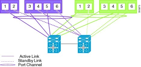
Figure 2-7 With vPC or VSS (Default)
Configuring Terminal Server Access for the Cisco Nexus Cloud Services Platform
Use this procedure to configure out-of-band terminal server access to the Cisco Nexus Cloud Services Platform.
BEFORE YOU BEGIN
Before starting this procedure, you must know or do the following:
- You are familiar with the “Rear Panel Description” section.
- You have the supplied DB-9–to–RJ-45 adapter to connect from the Cisco Nexus Cloud Services Platform to the supplied RJ-45 cable.
- You have the supplied RJ-45 cable to connect to a terminal server in you network.
This is the server you can access to connect to and configure the Cisco Nexus Cloud Services Platform software.
9600 baud and 8N1 (eight data bits, no parity, one stop-bit)
Warning Blank faceplates and cover panels serve three important functions: they prevent exposure to hazardous voltages and currents inside the chassis; they contain electromagnetic interference (EMI) that might disrupt other equipment; and they direct the flow of cooling air through the chassis. Do not operate the system unless all cards, faceplates, front covers, and rear covers are in place.
Statement 1019
DETAILED STEPS
Step 1![]() From the rear panel, connect the supplied DB-9–to–RJ-45 adapter to the serial port.
From the rear panel, connect the supplied DB-9–to–RJ-45 adapter to the serial port.

Step 2![]() Connect one end of the supplied RJ-45 cable to the adapter and the other end to a terminal server on your network.
Connect one end of the supplied RJ-45 cable to the adapter and the other end to a terminal server on your network.
Step 3![]() You have completed this procedure. Continue with “Powering On a Cisco Nexus Cloud Services Platform Appliance” section.
You have completed this procedure. Continue with “Powering On a Cisco Nexus Cloud Services Platform Appliance” section.
Configuring Terminal Server Access for the Cisco Nexus Cloud Services Platform
Use this procedure to configure out-of-band terminal server access to the Cisco Nexus 1110.
BEFORE YOU BEGIN
- Before starting this procedure, you must know or do the following:
- You are familiar with the “Rear Panel Description” section.
-
You have the supplied RJ-45 cable to connect to a terminal server in your network.
This is the server you can access to connect to and configure the Cisco Nexus 1110 software. -
Your terminal server is configured as follows:
9600 baud and 8N1 (eight data bits, no parity, one stop-bit)
Warning Blank faceplates and cover panels serve three important functions: they prevent exposure to hazardous voltages and currents inside the chassis; they contain electromagnetic interference (EMI) that might disrupt other equipment; and they direct the flow of cooling air through the chassis. Do not operate the system unless all cards, faceplates, front covers, and rear covers are in place.
Statement 1019
DETAILED STEPS
Step 1![]() From the rear panel, connect one end of the supplied RJ-45 cable to the serial port on the Cisco Nexus 1110 and the other end to the terminal server.
From the rear panel, connect one end of the supplied RJ-45 cable to the serial port on the Cisco Nexus 1110 and the other end to the terminal server.

Step 2![]() You have completed this procedure. Continue with “Powering On a Cisco Nexus Cloud Services Platform Appliance” section.
You have completed this procedure. Continue with “Powering On a Cisco Nexus Cloud Services Platform Appliance” section.
Powering On a Cisco Nexus Cloud Services Platform Appliance
Use this procedure to power on a Cisco Nexus Cloud Services Platform.
BEFORE YOU BEGIN
Before starting this procedure, you must know or do the following:
- You are familiar with the “Front Panel Description” section.
Warning Blank faceplates and cover panels serve three important functions: they prevent exposure to hazardous voltages and currents inside the chassis; they contain electromagnetic interference (EMI) that might disrupt other equipment; and they direct the flow of cooling air through the chassis. Do not operate the system unless all cards, faceplates, front covers, and rear covers are in place.
Statement 1019
DETAILED STEPS
Step 1![]() From the front panel, press and release the
Power
button.
From the front panel, press and release the
Power
button.
The Cisco Nexus 1110 boots up in main power mode.
The LED changes from blinking green to solid green.
Step 2![]() You have completed this procedure. Continue with the “Where to Go Next” section.
You have completed this procedure. Continue with the “Where to Go Next” section.
Connecting to the Cloud Services Platform CLI
Use this procedure to connect to the Cisco Nexus Cloud Services Platform CLI from your terminal server.
Step 1![]() Telnet to the Cisco Nexus 1110 IP address and port number.
Telnet to the Cisco Nexus 1110 IP address and port number.
telnet Cisco_Nexus_1110_IP_address port_number
The Cisco Nexus 1110 setup dialog starts.
---- System Admin Account Setup ----
Confirm the password for
Enter the password for "admin":
"admin":
Step 2![]() You have completed this procedure. Continue with “Where to Go Next” section.
You have completed this procedure. Continue with “Where to Go Next” section.
Where to Go Next
After you have installed the Cisco Nexus 1110 hardware, you can configure the software using the Cisco Nexus Cloud Services Platform Software Configuration Guide.
To reinstall or upgrade the Cisco Nexus 1110 software, see the Cisco Nexus Cloud Services Platform Software Installation and Upgrade Guide.
To upgrade the Cisco Nexus 1000V software on an existing virtual service blade, see the Cisco Nexus 1000V Software Upgrade Guide.
 Feedback