Cisco Nexus 1000V Software Upgrade Guide, Release 4.2(1)SV1(4)
Available Languages
Table Of Contents
Cisco Nexus 1000V Software Upgrade Guide, Release 4.2(1) SV1(4)
Running the Pre-Upgrade Utility
Prerequisites for Running the Pre-Upgrade Utility
Running the Pre-Upgrade Utility on a Microsoft Windows Platform
Running the Pre-Upgrade Utility Using the Cygwin Application
Installing the Cygwin Application
Running the Pre-Upgrade Utility in the Cygwin Application
Running the Pre-Upgrade Utility on a UNIX Platform
Information About the Software Upgrade
Upgrading to Release 4.2(1)SV1(4)
Upgrading from Release 4.0(4)SV1(3, 3a, or 3b) to Release 4.2(1)SV1(4)
Upgrading from Release 4.0(4)SV1(2) to Release 4.2(1)SV1(4)
Upgrading from Release 4.0(4)SV1(1) to Release 4.2(1)SV1(4)
Upgrading the VSMs: Release 4.0(4)SV1(2) to Release 4.0(4)SV1(3b)
Prerequisites to Upgrading the VSMs
Upgrading the VSMs: Release 4.0(4)SV1(1) to Release 4.0(4)SV1(3b)
Prerequisites to Upgrading the VSMs
Upgrading the VEMs: Release 4.0(4)SV1(2, 3, 3a, 3b) to Release 4.2(1)SV1(4)
Prerequisites to Upgrading VEMs
Upgrading the VEMs Manually: Release 4.0(4)SV1(2, 3, 3a, or 3b) to Release 4.2(1)SV1(4)
Upgrading the VEMs: Release 4.0(4)SV1(1) to Release 4.2(1)SV1(4)
Prerequisites to Upgrading VEMs
Upgrading the VEMs Using VMware Update Manager (VUM): Release 4.0(4)SV1(1) to Release 4.2(1)SV1(4)
Upgrading the VEMs Manually: Release 4.0(4)SV1(1) to Release 4.2(1)SV1(4)
Upgrading the VSMs to Release 4.2(1)SV1(4) Using the Upgrade Application
Prerequisites to Using the Cisco Nexus 1000V Upgrade Application
Prerequisites to Upgrading the VSMs
Prerequisites to Upgrading the VSMs
Prerequisites to Upgrading the VSMs
Accepting the VEM Upgrade in the vCenter Client
Prerequisites to Accepting the VEM Upgrade
Non-default (Jumbo) MTU Settings Symptoms and Solutions
Obtaining Documentation and Submitting a Service Request
Cisco Nexus 1000V Software Upgrade Guide, Release 4.2(1) SV1(4)
Revised: May 9, 2013
OL-22826-01
CautionThe upgrade procedure for Release 4.2(1)SV1(4) has changed. You must run the Pre-Upgrade Utility prior to beginning the upgrade. It is highly recommended that you read this document thoroughly before beginning the upgrade. For an overview of the new upgrade procedure, see the Understanding the Upgrade Process for the Cisco Nexus 1000V Release 4.2(1)SV1(4) video.
This document describes how to upgrade the Cisco Nexus 1000V software on a Virtual Supervisor Module (VSM) virtual machine (VM) and upgrading the Virtual Ethernet Module (VEM) which includes the following topics:
•
•
•
•
•
Audience
This guide is for network administrators and server administrators with the following experience and knowledge:
•
•
•
–
–
–
–
For more information about Cisco Nexus 1000V setup and implementation, see the Cisco Nexus 1000V Getting Started Guide, Release 4.2(1)SV1(4).
Obtaining the Software
You can obtain your upgrade-related software from the following sources (Table 1):
Table 1 Obtaining Software
Cisco
Download the Cisco Nexus 1000V Release 4.2(1)SV1(4) software from the Cisco website.
VMware
Download VMware software from VMware website.
For information about your software and platform compatibility, see the Cisco Nexus 1000V Compatibility Information, Release 4.2(1)SV1(4).
Running the Pre-Upgrade Utility

Note
Note
In Release 4.2(1)SV1(4), many feature enhancements have been incorporated for smoother operation. The feature checks performed by this script were not present in previous versions of the Cisco Nexus 1000V software. The Pre-Upgrade script checks for discrepancies and writes errors or notifications to the Pre-Upgrade-Check-Logs file in the PreUpgradeUtility folder. Errors must be corrected manually. If not corrected manually, notifications will be handled during the upgrade process.
The pre-upgrade utility checks for the following:
1.
2.
3.
4.
5.
6.
7.
8.
9.
10.
11.
12.
13.
14.
15.
16.
Prerequisites for Running the Pre-Upgrade Utility
The Pre-Upgrade Utility has the following prerequisite:
•
This utility can be run on the following platforms:
•
•
Note
Running the Pre-Upgrade Utility on a Microsoft Windows Platform
The Pre-Upgrade Utility must be run using the following open-source Cygwin application:
•
Running the Pre-Upgrade Utility Using the Cygwin Application
Running the Pre-Upgrade Utility using the Cygwin application is a two-step process:
1.
2.
Installing the Cygwin Application
Step 1
Step 2
You may choose the latest version.
Note
Step 3
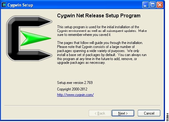
The Cygwin Setup window opens. See Figure 1.
Figure 1 Cygwin Setup Screen
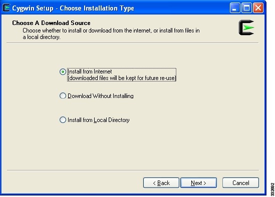
Step 4
The Choose a Download Source window opens. See Figure 2.
Figure 2 Choose a Download Source Screen
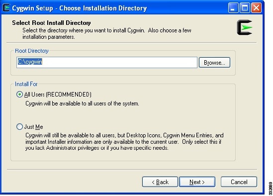
Step 5
Note
The Select Root Install Directory window opens. See Figure 3.
Figure 3 Select Root Install Directory Screen
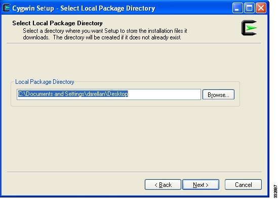
Step 6
The Select Local Package Directory window opens. See Figure 4.
Note
Figure 4 Select Local Package Directory Screen
Step 7
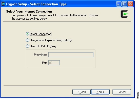
The Select Your Internet Connection window opens. See Figure 5.
Figure 5 Select Your Internet Connection Screen
Step 8
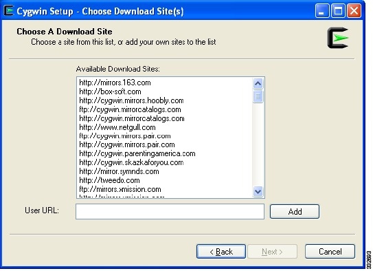
The Choose a Download Site window opens. See Figure 6.
Figure 6 Choose A Download Site Screen
Step 9
The Progress window opens. See Figure 7.
The installer downloads a list of available packages from the site that you selected.
Figure 7 Progress Screen

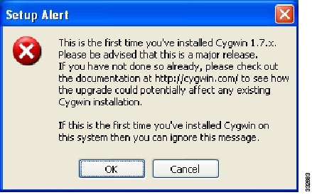
Figure 8 Setup Alert Screen
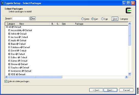
Step 10
The Select Packages window opens. See Figure 9.
For a basic installation, some packages are selected by default.

Tip
Figure 9 Select Packages Screen
Step 11
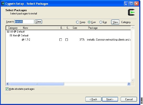
As you enter the package name, the screen updates with the available packages. See Figure 10.
Note
Figure 10 Select Packages Screen
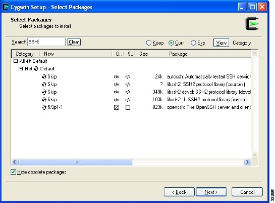
Step 12
Step 13
Figure 11 Select OpenSSH Packages Screen
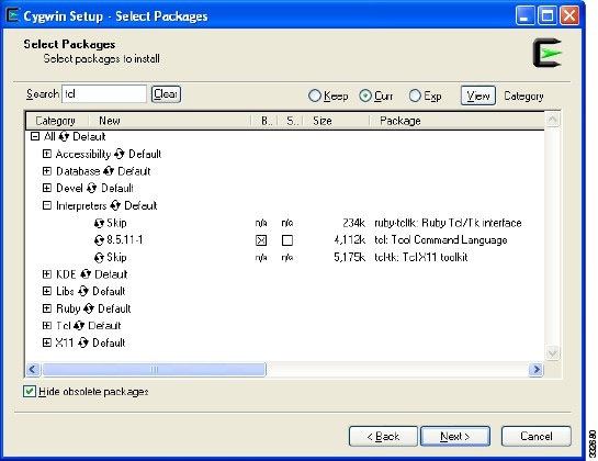
Step 14
Step 15
Figure 12 Select Tcl Packages Screen
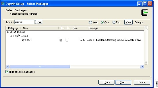
Step 16
Step 17
Figure 13 Select Expect Packages Screen
Step 18
Step 19
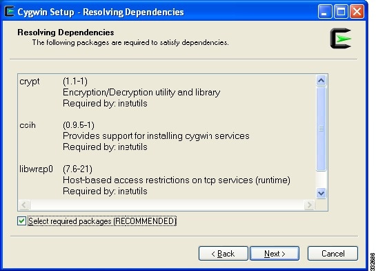
In Cygwin 1.7, you might see a screen that displays a warning ("Resolving Dependencies") and a list of additional packages that are required by the packages that you have already selected.
The Resolving Dependencies screen opens. See Figure 14.
Figure 14 Resolving Dependencies Screen
Step 20
The downloading process begins after you choose the packages.
Figure 15 Download Progress Screen
Note
Following package installation, any installation dependent configuration scripts are run to complete the setup process.
Note
The Create Icons window opens. See Figure 16.
Figure 16 Create Icons Screen
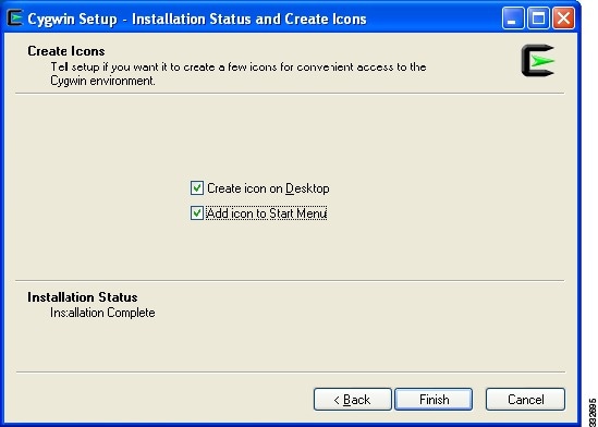
Step 21
Running the Pre-Upgrade Utility in the Cygwin Application
Prerequisites:
•
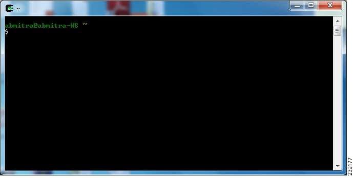
Step 1
Step 2
The Cygwin application window opens. See Figure 17.
Figure 17 Terminal Window
Step 3
Step 4
$ expect pre-upgrade-check-4.2\(1\)SV1\(4\).tcl ip-address username password
  [telnet | ssh]
•
•
Note
Figure 18 Telnet Option Window

Note
Step 5
•
•
Step 6
Step 7
Running the Pre-Upgrade Utility on a UNIX Platform
Caution
Step 1
Step 2
Note
Step 3
tclsh pre-upgrade-check-4.2(1)SV1(4).tcl ip-address username password [telnet | ssh]•
•
Example:tclsh pre-upgrade-check-4.2(1)SV1(4).tcl 10.0.0.2 user1 mynewpassword telnetThe checks being performed and the results are displayed . If there are any errors, possible corrective actions are listed. The log file containing the errors and notifications is Pre-Upgrade-App-date-time.txt. in the PreUpgradeUtility/Pre-Upgrade-Check-Logs folder.
Step 4
•
•
Step 5
Step 6
Information About the Software Upgrade
Caution
Figure 19
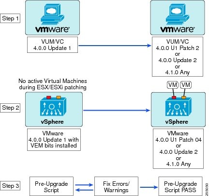
Non-Disruptive Upgrade Steps
This section provides information about the software upgrade. This section describes important points about the software upgrade:
•
A non-disruptive upgrade takes place when you install one of the following VMware releases listed in Table 2.
Note
Table 2 Non-Disruptive Patch Level
4.0.0
ESX/ESXi400-201002001
upgrade-from-esxi4.0-4.0_update02
4.1.0
Any patch level
Note
•
•
•
–
Caution
•
Information About Licensing
The following table summarizes licensing information following the upgrade.
This release supports installation of additional evaluation license files.
For more licensing details, see the Cisco Nexus 1000V License Configuration Guide, Release 4.2(1)SV1(4).
For information about limitations and caveats, see the Cisco Nexus 1000V Release Notes, Release 4.2(1)SV1(4).
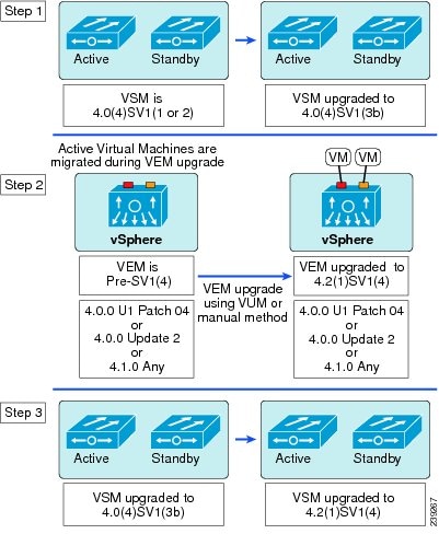
Upgrading to Release 4.2(1)SV1(4)
The upgrade procedures for the previous releases are covered in the following sections.
Note
Upgrading from Release 4.0(4)SV1(3, 3a, or 3b) to Release 4.2(1)SV1(4)
Note
Note
For ESX/ESXi 4.0.0 releases and later, the minimum VC/VUM version required is 208111/282702.
Caution
To perform a software upgrade from Release 4.0(4)SV1(3, 3a, or 3b) to Release 4.2(1)SV1(4), follow these steps:
Step 1
Step 2
Figure 20

Upgrading from Release 4.0(4)SV1(3, 3a, or 3b) to Release 4.2(1)SV1(4)
Upgrading from Release 4.0(4)SV1(2) to Release 4.2(1)SV1(4)
Note
For ESX/ESXi 4.0.0 releases and later, the minimum VC/VUM version required is 208111/282702.
To perform the software upgrade from Release 4.0(4)SV1(2) to Release 4.2(1)SV1(4), follow these steps:
Step 1
Step 2
Step 3
Figure 21
Upgrading from Release 4.0(4)SV1(2) to Release 4.2(1)SV1(4)
Upgrading from Release 4.0(4)SV1(1) to Release 4.2(1)SV1(4)
Note
For ESX/ESXi 4.0.0 releases and later, the minimum VC/VUM version required is 208111/282702.
To perform a software upgrade from Release 4.0(4)SV1(1) to Release 4.2(1)SV1(4), follow these steps:
Step 1
Step 2
Step 3
Figure 22
Upgrading from Release 4.0(4)SV1(1) to Release 4.2(1)SV1(4)
Upgrading the VSMs
This section describes the VSM upgrade procedures that are supported in this release:
•
•
•
Upgrading the VSMs: Release 4.0(4)SV1(2) to Release 4.0(4)SV1(3b)
This section describes the VSM upgrade from Release 4.0(4)SV1(2) to Release 4.0(4)SV1(3b).
Prerequisites to Upgrading the VSMs
The following are prerequisites to upgrading the VSMs:
•
•
•
•
–
–
•
•
To perform a VSM software upgrade from Release 4.0(4)SV1(2) to Release 4.0(4)SV1(3b), follow these steps:
Note
Note
Step 1
switch# copy scp://root@192.0.2.13/N1K-VSM-images/nexus-1000v-mz.4.0.4.SV1.3b.bin
bootflash:
Enter vrf (If no input, current vrf 'default' is considered):root@192.0.2.13's password:nexus-1000v-mz.4.0.4.SV1.3b.bin 100% 20MB 1.1MB/s 00:19switch#switch# copy scp://root@192.0.2.13/N1K-VSM-images/nexus-1000v-kickstart-mz.4.0.4.SV1.3b.bin bootflash:Enter vrf (If no input, current vrf 'default' is considered):root@192.0.2.13's password:nexus-1000v-kickstart-mz.4.0.4.SV1.3b.bin 100% 20MB 1.1MB/s 00:19switch#switch# dir bootflash:154 Jan 27 15:21:06 2010 .ovfconfigured77824 Mar 03 07:31:09 2010 accounting.log16384 Dec 09 13:56:23 2009 lost+found/21408768 Dec 09 13:57:21 2009 nexus-1000v-kickstart-mz.4.0.4.SV1.2.bin21982208 Jan 21 18:28:58 2010 nexus-1000v-kickstart-mz.4.0.4.SV1.3b.bin73068811 Dec 09 13:57:32 2009 nexus-1000v-mz.4.0.4.SV1.2.bin62280256 Jan 21 18:29:35 2010 nexus-1000v-mz.4.0.4.SV1.3b.bin4096 Dec 09 13:58:18 2009 vdc_2/4096 Dec 09 13:58:18 2009 vdc_3/4096 Dec 09 13:58:18 2009 vdc_4/Usage for bootflash://sup-local333910016 bytes used2054361088 bytes free2388271104 bytes totalStep 2
Note
switch# install all system bootflash:nexus-1000v-mz.4.0.4.SV1.3b.bin kickstart
bootflash:nexus-1000v-kickstart-mz.4.0.4.SV1.3b.bin
System image sync to standby is in progress...System image is synced to standby.Kickstart image sync to Standby is in progress...Kickstart image is synced to standby.Boot variables are updated to running configuration.Step 3
switch# copy running-config startup-config[########################################] 100%Step 4
switch# show startup-config | include bootboot kickstart bootflash:/nexus-1000v-kickstart-mz.4.0.4.SV1.3b.bin sup-1boot system bootflash:/nexus-1000v-mz.4.0.4.SV1.3b.bin sup-1boot kickstart bootflash:/nexus-1000v-kickstart-mz.4.0.4.SV1.3b.bin sup-2boot system bootflash:/nexus-1000v-mz.4.0.4.SV1.3b.bin sup-2switch# show running-config | include bootboot kickstart bootflash:/nexus-1000v-kickstart-mz.4.0.4.SV1.3b.bin sup-1boot system bootflash:/nexus-1000v-mz.4.0.4.SV1.3b.bin sup-1boot kickstart bootflash:/nexus-1000v-kickstart-mz.4.0.4.SV1.3b.bin sup-2boot system bootflash:/nexus-1000v-mz.4.0.4.SV1.3b.bin sup-2Step 5
switch# show modMod Ports Module-Type Model Status--- ----- -------------------------------- ------------------ ------------1 0 Virtual Supervisor Module Nexus1000V active *2 0 Virtual Supervisor Module Nexus1000V ha-standby3 248 Virtual Ethernet Module NA ok4 248 Virtual Ethernet Module NA okMod Sw Hw--- --------------- ------1 4.0(4)SV1(2) 0.02 4.0(4)SV1(2) 0.03 4.0(4)SV1(2) 1.114 4.0(4)SV1(2) 1.11Mod MAC-Address(es) Serial-Num--- -------------------------------------- ----------1 00-19-07-6c-5a-a8 to 00-19-07-6c-62-a8 NA2 00-19-07-6c-5a-a8 to 00-19-07-6c-62-a8 NA3 02-00-0c-00-03-00 to 02-00-0c-00-03-80 NA4 02-00-0c-00-04-00 to 02-00-0c-00-04-80 NAMod Server-IP Server-UUID Server-Name--- --------------- ------------------------------------ --------------------1 10.78.109.100 NA NA2 10.78.109.100 NA NA3 10.78.109.104 1ee15784-f2e8-383e-8132-9026577ca1bb 10.78.109.1044 10.78.109.102 44454c4c-4700-104e-804d-cac04f563153 10.78.109.102Step 6
Used module 2 in the following example because module 2 is the standby module. After reloading the standby VSM, the active VSM that is running software release 4.0(4)SV1(2), synchronizes with the standby VSM running Release 4.0(4)SV1(3b).
switch# reload module 2This command will reboot standby supervisor module. (y/n)? [n] yabout to reset standby supswitch# 2010 Feb 11 09:57:42 n1000v %PLATFORM-2-PFM_MODULE_RESET: Manual restart of Module 2 from Command Line Interface2010 Feb 11 09:57:49 n1000v %PLATFORM-2-MOD_REMOVE: Module 2 removed (Serial number T5056972D88)2010 Feb 11 09:57:53 n1000v %(0x436D) for service "netstack" (PID 3176): Connection timed out (110).
Note
Step 7
switch# show modMod Ports Module-Type Model Status--- ----- -------------------------------- ------------------ ------------1 0 Virtual Supervisor Module Nexus1000V active *2 0 Virtual Supervisor Module Nexus1000V ha-standby3 248 Virtual Ethernet Module NA ok4 248 Virtual Ethernet Module NA okMod Sw Hw--- --------------- ------1 4.0(4)SV1(2) 0.02 4.0(4)SV1(3b) 0.03 4.0(4)SV1(2) 1.114 4.0(4)SV1(2) 1.11Mod MAC-Address(es) Serial-Num--- -------------------------------------- ----------1 00-19-07-6c-5a-a8 to 00-19-07-6c-62-a8 NA2 00-19-07-6c-5a-a8 to 00-19-07-6c-62-a8 NA3 02-00-0c-00-03-00 to 02-00-0c-00-03-80 NA4 02-00-0c-00-04-00 to 02-00-0c-00-04-80 NAMod Server-IP Server-UUID Server-Name--- --------------- ------------------------------------ --------------------1 10.78.109.100 NA NA2 10.78.109.100 NA NA3 10.78.109.104 1ee15784-f2e8-383e-8132-9026577ca1bb 10.78.109.1044 10.78.109.102 44454c4c-4700-104e-804d-cac04f563153 10.78.109.102* this terminal session
Note
Step 8
switch# system switchoverWhen the modules are switched over, the primary module reloads and returns as the standby VSM with the new software version.
Step 9
In the following example, module 2 is the active module and module 1 is now the standby module.
switch# show modMod Ports Module-Type Model Status--- ----- -------------------------------- ------------------ ------------1 0 Virtual Supervisor Module Nexus1000V ha-standby2 0 Virtual Supervisor Module Nexus1000V active *3 248 Virtual Ethernet Module NA ok4 248 Virtual Ethernet Module NA okMod Sw Hw--- --------------- ------1 4.0(4)SV1(3b) 0.02 4.0(4)SV1(3b) 0.03 4.0(4)SV1(2) 1.114 4.0(4)SV1(2) 1.11Mod MAC-Address(es) Serial-Num--- -------------------------------------- ----------1 00-19-07-6c-5a-a8 to 00-19-07-6c-62-a8 NA2 00-19-07-6c-5a-a8 to 00-19-07-6c-62-a8 NA3 02-00-0c-00-03-00 to 02-00-0c-00-03-80 NA4 02-00-0c-00-04-00 to 02-00-0c-00-04-80 NAMod Server-IP Server-UUID Server-Name--- --------------- ------------------------------------ --------------------1 10.78.109.100 NA NA2 10.78.109.100 NA NA3 10.78.109.104 1ee15784-f2e8-383e-8132-9026577ca1bb 10.78.109.1044 10.78.109.102 44454c4c-4700-104e-804d-cac04f563153 10.78.109.102* this terminal session
Note
Use the system switchover command, to set module 1 as the active module and module 2 as the standby module.
Step 10
Step 11
For details, see the "Upgrading the VEMs: Release 4.0(4)SV1(2, 3, 3a, 3b) to Release 4.2(1)SV1(4)" section.
Upgrading the VSMs: Release 4.0(4)SV1(1) to Release 4.0(4)SV1(3b)
This section describes the VSM upgrade from Release 4.0(4)SV1(1) to Release 4.0(4)SV1(3b).
Prerequisites to Upgrading the VSMs
The following are prerequisites to upgrading the VSMs:
•
•
•
•
–
–
•
•
For information about backing up a configuration file, see the Cisco Nexus 1000V System Management Configuration Guide, Release 4.2(1)SV1(4).
To perform a VSM software upgrade from Release 4.0(4)SV1(1) to Release 4.0(4)SV1(3b), follow these steps:
Note
Step 1
Step 2
Step 3
switch# config tswitch(config)# no boot systemswitch(config)# no boot kickstartStep 4
switch(config)# boot system bootflash:nexus-1000v-mzg.4.0.4.SV1.3b.bin2009 Dec 13 15:50:40.568 n1k-av %BOOTVAR-5-IMAGE_NOTEXISTS: Warning: image nexus-1000v-mz.4.0.4.SV1.3b.bin doesn't exist on sup22009 Dec 13 15:51:28.236 n1k-av %BOOTVAR-5-AUTOCOPY_SUCCEED: auto-copy of file /bootflash/nexus-1000v-mz.4.0.4.SV1.3b.bin to standby supervisor succeedswitch(config)# boot kickstart bootflash:nexus-1000v-kickstart-mzg.4.0.4.SV1.3b.bin2009 Dec 13 15:54:03.093 n1k-av %BOOTVAR-5-IMAGE_NOTEXISTS: Warning: image nexus-1000v-kickstart-mz.4.0.4.SV1.3b.bin doesn't exist on sup22009 Dec 13 15:54:20.966 n1k-av %BOOTVAR-5-AUTOCOPY_SUCCEED: auto-copy of file /bootflash/nexus-1000v-kickstart-mz.4.0.4.SV1.3b.bin to standby supervisor succeedswitch(config)#
Note
Caution
Step 5
switch(config)# copy running-config startup-config[########################################] 100%switch(config)#Step 6
switch# show startup-config | include bootboot kickstart bootflash:/nexus-1000v-kickstart-mz.4.0.4.SV1.3b.bin sup-1boot system bootflash:/nexus-1000v-mz.4.0.4.SV1.3b.bin sup-1boot kickstart bootflash:/nexus-1000v-kickstart-mz.4.0.4.SV1.3b.bin sup-2boot system bootflash:/nexus-1000v-mz.4.0.4.SV1.3b.bin sup-2switch# show running-config | include bootboot kickstart bootflash:/nexus-1000v-kickstart-mz.4.0.4.SV1.3b.bin sup-1boot system bootflash:/nexus-1000v-mz.4.0.4.SV1.3b.bin sup-1boot kickstart bootflash:/nexus-1000v-kickstart-mz.4.0.4.SV1.3b.bin sup-2boot system bootflash:/nexus-1000v-mz.4.0.4.SV1.3b.bin sup-2Step 7
switch# show modMod Ports Module-Type Model Status--- ----- -------------------------------- ------------------ ------------1 0 Virtual Supervisor Module Nexus1000V active *2 0 Virtual Supervisor Module Nexus1000V ha-standby3 248 Virtual Ethernet Module NA ok4 248 Virtual Ethernet Module NA okMod Sw Hw--- --------------- ------1 4.0(4)SV1(1) 0.02 4.0(4)SV1(1) 0.03 4.0(4)SV1(1) 1.114 4.0(4)SV1(1) 1.11Mod MAC-Address(es) Serial-Num--- -------------------------------------- ----------1 00-19-07-6c-5a-a8 to 00-19-07-6c-62-a8 NA2 00-19-07-6c-5a-a8 to 00-19-07-6c-62-a8 NA3 02-00-0c-00-03-00 to 02-00-0c-00-03-80 NA4 02-00-0c-00-04-00 to 02-00-0c-00-04-80 NAMod Server-IP Server-UUID Server-Name--- --------------- ------------------------------------ --------------------1 10.78.109.100 NA NA2 10.78.109.100 NA NA3 10.78.109.104 1ee15784-f2e8-383e-8132-9026577ca1bb 10.78.109.1044 10.78.109.102 44454c4c-4700-104e-804d-cac04f563153 10.78.109.102
Note
Step 8
switch# reloadThis command will reboot the system. (y/n)? [n] yswitch#The upgraded VSMs start up with the new software version.
Step 9
switch# show modMod Ports Module-Type Model Status--- ----- -------------------------------- ------------------ ------------1 0 Virtual Supervisor Module Nexus1000V active *2 0 Virtual Supervisor Module Nexus1000V ha-standby3 248 Virtual Ethernet Module NA ok4 248 Virtual Ethernet Module NA okMod Sw Hw--- --------------- ------1 4.0(4)SV1(3b) 0.02 4.0(4)SV1(3b) 0.03 4.0(4)SV1(1) 1.114 4.0(4)SV1(1) 1.11Mod MAC-Address(es) Serial-Num--- -------------------------------------- ----------1 00-19-07-6c-5a-a8 to 00-19-07-6c-62-a8 NA2 00-19-07-6c-5a-a8 to 00-19-07-6c-62-a8 NA3 02-00-0c-00-03-00 to 02-00-0c-00-03-80 NA4 02-00-0c-00-04-00 to 02-00-0c-00-04-80 NAMod Server-IP Server-UUID Server-Name--- --------------- ------------------------------------ --------------------1 10.78.109.100 NA NA2 10.78.109.100 NA NA3 10.78.109.104 1ee15784-f2e8-383e-8132-9026577ca1bb 10.78.109.1044 10.78.109.102 44454c4c-4700-104e-804d-cac04f563153 10.78.109.102* this terminal session
Note
Step 10
Step 11
For details, see the "Upgrading the VEMs: Release 4.0(4)SV1(1) to Release 4.2(1)SV1(4)" section.
Upgrading the VEMs
This section describes the VEM upgrade procedures that are supported in this release:
•
•
Before upgrading the VEMs, note the following important points:
•
•
•
•
•
Caution
Upgrading the VEMs: Release 4.0(4)SV1(2, 3, 3a, 3b) to Release 4.2(1)SV1(4)
This section describes the steps to upgrade VEMs from Release 4.0(4)SV1(2, 3, 3a, 3b) to Release 4.2(1)SV1(4) and includes the following topics:
•
Prerequisites to Upgrading VEMs
The following are prerequisites to upgrading the VEMs:
•
•
•
Upgrading the VEMs Using VMware Update Manager (VUM): Release 4.0(4)SV1(2, 3, 3a, or 3b) to Release 4.2(1)SV1(4)
To upgrade the VEMs using VUM, follow these steps:
Note
Note
Caution
Step 1
These files will be present in the zip folder of the FCS.
Step 2
switch (config)# show vmware vem upgrade statusUpgrade VIBs: System VEM ImageUpgrade Status:Upgrade Notification Sent Time:Upgrade Status Time(vCenter):Upgrade Start Time:Upgrade End Time(vCenter):Upgrade Error:Upgrade Bundle ID:VSM: VEM400-201007101-BGDVS: VEM400-201007101-BGStep 3
switch (config)# vmware vem upgrade update-vibs bootflash:vem-release_final.tar.gzStep 4
switch (config)# show vmware vem upgrade statusUpgrade VIBs: Upgrade VEM ImageUpgrade Status:Upgrade Notification Sent Time:Upgrade Status Time(vCenter):Upgrade Start Time:Upgrade End Time(vCenter):Upgrade Error:Upgrade Bundle ID:VSM: VEM400-201101030-RGDVS: VEM400-201007101-BG
Note
Step 5
switch (config)# vmware vem upgrade notifyWarning:Please ensure the hosts are running compatible ESX versions for the upgrade. Refer to corresponding "Cisco Nexus 1000V and VMware Compatibility Information" guide.Step 6
switch# show vmware vem upgrade statusUpgrade VIBs: Upgrade VEM ImageUpgrade Status: Upgrade Availability Notified in vCenterUpgrade Notification Sent Time: Sun May 9 22:04:54 2010Upgrade Status Time(vCenter):Upgrade Start Time:Upgrade End Time(vCenter):Upgrade Error:Upgrade Bundle ID:VSM: VEM400-201101030-RGDVS: VEM400-201007101-BG
Note
Step 7
For details about how the server administrator accepts the VEM upgrade, see the "Accepting the VEM Upgrade in the vCenter Client" section.
Coordinate the notification acceptance with the server administrator. After the server administrator accepts the upgrade, proceed with the VEM upgrade.
switch# show vmware vem upgrade statusUpgrade VIBs: Upgrade VEM ImageUpgrade Status: Upgrade Accepted by vCenter AdminUpgrade Notification Sent Time: Sun May 9 22:04:54 2010Upgrade Status Time(vCenter): Tue May 11 07:42:32 2010Upgrade Start Time:Upgrade End Time(vCenter):Upgrade Error:Upgrade Bundle ID:VSM: VEM400-201101030-RGDVS: VEM400-201007101-BG
Note
Step 8
Caution
vCenter locks the DVS and triggers VUM to upgrade the VEMs.
switch# vmware vem upgrade proceedswitch# show vmware vem upgrade statusUpgrade VIBs: Upgrade VEM ImageUpgrade Status: Upgrade In Progress in vCenterUpgrade Notification Sent Time: Wed Mar 17 15:19:05 2010Upgrade Status Time(vCenter): Wed Mar 17 17:28:46 2010Upgrade Start Time: Wed Mar 17 15:20:06 2010Upgrade End Time(vCenter):Upgrade Error:Upgrade Bundle ID:VSM: VEM400-201101030-RGDVS: VEM400-201101030-RG
Note
Note
Step 9
Note
switch# show vmware vem upgrade statusUpgrade VIBs: System VEM ImageUpgrade Status: Upgrade Complete in vCenterUpgrade Notification Sent Time: Wed Mar 17 15:19:05 2010Upgrade Status Time(vCenter): Wed Mar 17 17:28:46 2010Upgrade Start Time: Wed Mar 17 15:20:06 2010Upgrade End Time(vCenter): Wed Mar 17 17:30:48 2010Upgrade Error:Upgrade Bundle ID:VSM: VEM400-201101030-RGDVS: VEM400-201101030-RG
Note
Step 10
switch# vmware vem upgrade completeswitch# show vmware vem upgrade statusUpgrade VIBs: Upgrade VEM ImageUpgrade Status:Upgrade Notification Sent Time:Upgrade Status Time(vCenter):Upgrade Start Time:Upgrade End Time(vCenter):Upgrade Error:Upgrade Bundle ID:VSM: VSM130-201010110-BGDVS: VSM130-201010110-BGStep 11
switch# show modMod Ports Module-Type Model Status--- ----- -------------------------------- ------------------ ------------1 0 Virtual Supervisor Module Nexus1000V ha-standby2 0 Virtual Supervisor Module Nexus1000V active *3 248 Virtual Ethernet Module NA ok4 248 Virtual Ethernet Module NA okMod Sw Hw--- --------------- ------1 4.2(1)SV1(3b) 0.02 4.2(1)SV1(3b) 0.03 4.2(1)SV1(4) VMware ESXi 4.0.0 Releasebuild-261974 (1.20)4 4.2(1)SV1(4) VMware ESXi 4.1.0 Releasebuild-260247 (2.0)Mod MAC-Address(es) Serial-Num--- -------------------------------------- ----------1 00-19-07-6c-5a-a8 to 00-19-07-6c-62-a8 NA2 00-19-07-6c-5a-a8 to 00-19-07-6c-62-a8 NA3 02-00-0c-00-03-00 to 02-00-0c-00-03-80 NA4 02-00-0c-00-04-00 to 02-00-0c-00-04-80 NAMod Server-IP Server-UUID Server-Name--- --------------- ------------------------------------ --------------------1 10.78.109.100 NA NA2 10.78.109.100 NA NA3 10.78.109.104 1ee15784-f2e8-383e-8132-9026577ca1bb 10.78.109.1044 10.78.109.102 44454c4c-4700-104e-804d-cac04f563153 10.78.109.102* this terminal session
Note
Step 12
Caution
For details, see the "Upgrading the VSMs to Release 4.2(1)SV1(4) Using the Upgrade Application" section.
Upgrading the VEMs Manually: Release 4.0(4)SV1(2, 3, 3a, or 3b) to Release 4.2(1)SV1(4)
To manually install or upgrade the Cisco Nexus 1000V VEM on an ESX/ESXi host, follow the steps in the "Installing or Upgrading the VEM Software Using the CLI" section in the Cisco Nexus 1000V Virtual Ethernet Module Software Installation and Upgrade Guide, Release 4.2(1)SV1(4).
To upgrade the VEMs manually, perform the following steps as network administrator:
Note
Note
Caution
Step 1
These files will be present in the zip folder of the FCS.
Step 2
switch (config)# vmware vem upgrade update-vibs bootflash:vem-release_final.tar.gzStep 3
switch (config)# vmware vem upgrade notifyWarning:Please ensure the hosts are running compatible ESX versions for the upgrade. Refer to corresponding "Cisco Nexus 1000V and VMware Compatibility Information" guide.Step 4
switch (config)# show vmware vem upgrade statusUpgrade Status: Upgrade Availability Notified in vCenterUpgrade Notification Sent Time: Sun May 9 22:04:54 2010Upgrade Status Time(vCenter):Upgrade Start Time:Upgrade End Time(vCenter):Upgrade Error:Upgrade Bundle ID:VSM: VEM400-201101030-RGDVS: VEM400-201007101-BGStep 5
For details about the server administrator accepting the VEM upgrade, see the "Accepting the VEM Upgrade in the vCenter Client" section.
After the server administrator accepts the upgrade, proceed with the VEM upgrade.
switch# show vmware vem upgrade statusUpgrade VIBs: Upgrade VEM ImageUpgrade Status: Upgrade Accepted by vCenter AdminUpgrade Notification Sent Time: Sun May 9 22:04:54 2010Upgrade Status Time(vCenter): Tue May 11 07:42:32 2010Upgrade Start Time:Upgrade End Time(vCenter):Upgrade Error:Upgrade Bundle ID:VSM: VEM400-201101030-RGDVS: VEM400-201007101-BGStep 6
•
•
Step 7
Note
Enter the vmware vem upgrade proceed command so that the Cisco Nexus 1000V Bundle ID on the vCenter Server gets updated. If VUM is enabled and you do not update the Bundle ID, an incorrect VIB version is pushed to the VEM when you next add the ESX to VSM.
switch# vmware vem upgrade proceed
Note
switch# show vmware vem upgrade statusUpgrade VIBs: Upgrade VEM ImageUpgrade Status: Upgrade Errored in vCenter. Please check UpgradeError for more details.Upgrade Notification Sent Time: Wed Mar 17 15:19:05 2010Upgrade Status Time(vCenter): Wed Mar 17 17:28:46 2010Upgrade Start Time: Wed Mar 17 15:20:06 2010Upgrade End Time(vCenter):Upgrade Error: [VMware vCenter Server 4.1.0 build-258902] A general system error occurred: unknown internal error.Upgrade Bundle ID:VSM: VEM400-201101030-RGDVS: VEM400-201101030-RGStep 8
Note
switch# show vmware vem upgrade statusUpgrade VIBs: Upgrade VEM ImageUpgrade Status: Upgrade Complete in vCenterUpgrade Notification Sent Time: Wed Mar 17 15:19:05 2010Upgrade Status Time(vCenter): Wed Mar 17 17:28:46 2010Upgrade Start Time: Wed Mar 17 15:20:06 2010Upgrade End Time(vCenter): Wed Mar 17 17:28:48 2010Upgrade Error:Upgrade Bundle ID:VSM: VEM400-201101030-RGDVS: VEM400-201101030-RGStep 9
The server administrator performs the manual upgrade using the vi host update or the ESX/ESXi update. For details, see the Cisco Nexus 1000V Virtual Ethernet Module Software Installation and Upgrade Guide, Release 4.2(1)SV1(4).
Step 10
switch# vmware vem upgrade completeswitch# show vmware vem upgrade statusUpgrade VIBs: Upgrade VEM ImageUpgrade Status:Upgrade Notification Sent Time:Upgrade Status Time(vCenter):Upgrade Start Time:Upgrade End Time(vCenter):Upgrade Error:Upgrade Bundle ID:VSM: VEM400-201101030-RGDVS: VEM400-201101030-RGStep 11
switch# show modMod Ports Module-Type Model Status--- ----- -------------------------------- ------------------ ------------1 0 Virtual Supervisor Module Nexus1000V ha-standby2 0 Virtual Supervisor Module Nexus1000V active *3 248 Virtual Ethernet Module NA ok4 248 Virtual Ethernet Module NA okMod Sw Hw--- --------------- ------1 4.2(1)SV1(3b) 0.02 4.2(1)SV1(3b) 0.03 4.2(1)SV1(4) VMware ESXi 4.0.0 Releasebuild-261974 (1.20)4 4.2(1)SV1(4) VMware ESXi 4.1.0 Releasebuild-260247 (2.0)Mod MAC-Address(es) Serial-Num--- -------------------------------------- ----------1 00-19-07-6c-5a-a8 to 00-19-07-6c-62-a8 NA2 00-19-07-6c-5a-a8 to 00-19-07-6c-62-a8 NA3 02-00-0c-00-03-00 to 02-00-0c-00-03-80 NA4 02-00-0c-00-04-00 to 02-00-0c-00-04-80 NAMod Server-IP Server-UUID Server-Name--- --------------- ------------------------------------ --------------------1 10.78.109.100 NA NA2 10.78.109.100 NA NA3 10.78.109.104 1ee15784-f2e8-383e-8132-9026577ca1bb 10.78.109.1044 10.78.109.102 44454c4c-4700-104e-804d-cac04f563153 10.78.109.102* this terminal session
Note
Step 12
Caution
For details, see the "Upgrading the VSMs to Release 4.2(1)SV1(4) Using the Upgrade Application" section.
Upgrading the VEMs: Release 4.0(4)SV1(1) to Release 4.2(1)SV1(4)
This section describes the steps to upgrade VEMs from Release 4.0(4)SV1(1) to Release 4.2(1)SV1(4) and includes the following topics:
•
•
Prerequisites to Upgrading VEMs
The following are prerequisites to upgrading the VEMs:
•
•
•
•
Upgrading the VEMs Using VMware Update Manager (VUM): Release 4.0(4)SV1(1) to Release 4.2(1)SV1(4)
To upgrade the VEMs using VUM, follow these steps:
Note
Caution
Step 1
Step 2
switch (config)# vmware vem upgrade update-vibs bootflash:vem-release_final.tar.gzStep 3
switch (config)# vmware vem upgrade notifyWarning:Please ensure the hosts are running compatible ESX versions for the upgrade. Refer to corresponding "Cisco Nexus 1000V and VMware Compatibility Information" guide.Step 4
switch (config)# show vmware vem upgrade statusUpgrade VIBs: Upgrade VEM ImageUpgrade Status: Upgrade Availability Notified in vCenterUpgrade Notification Sent Time: Sun May 9 22:04:54 2010Upgrade Status Time(vCenter):Upgrade Start Time:Upgrade End Time(vCenter):Upgrade Error:Upgrade Bundle ID:VSM: VEM400-20100830100-BGDVS: VEM400-200904001-BG
Note
Step 5
For details about the server administrator accepting the VEM upgrade, see the "Accepting the VEM Upgrade in the vCenter Client" section.
Coordinate the notification acceptance with the server administrator. After the server administrator accepts the upgrade, proceed with the VEM upgrade.
switch (config)# show vmware vem upgrade statusUpgrade VIBs: Upgrade VEM ImageUpgrade Status: Upgrade Accepted by vCenter AdminUpgrade Notification Sent Time: Sun May 9 22:04:54 2010Upgrade Status Time(vCenter): Tue May 11 07:42:32 2010Upgrade Start Time:Upgrade End Time(vCenter):Upgrade Error:Upgrade Bundle ID:VSM: VEM400-20100830100-BGDVS: VEM400-200904001-BGStep 6
vCenter locks the DVS and triggers VUM to upgrade the VEMs.
Note
switch# vmware vem upgrade proceedswitch# show vmware vem upgrade statusUpgrade VIBs: Upgrade VEM ImageUpgrade Status: Upgrade Complete in vCenterUpgrade Notification Sent Time: Wed Mar 17 15:19:05 2010Upgrade Status Time(vCenter): Wed Mar 17 17:28:46 2010Upgrade Start Time: Wed Mar 17 15:20:06 2010Upgrade End Time(vCenter):Upgrade Error:Upgrade Bundle ID:VSM: VSM130-201010110-BGDVS: VSM130-201010110-BGStep 7
Note
switch# show vmware vem upgrade statusUpgrade VIBs: Upgrade VEM ImageUpgrade Status: Upgrade Complete in vCenterUpgrade Notification Sent Time: Wed Mar 17 15:19:05 2010Upgrade Status Time(vCenter): Wed Mar 17 17:28:46 2010Upgrade Start Time: Wed Mar 17 15:20:06 2010Upgrade End Time(vCenter): Wed Mar 17 17:30:48 2010Upgrade Error:Upgrade Bundle ID:VSM: VSM130-201010110-BGDVS: VSM130-201010110-BGStep 8
switch# vmware vem upgrade completeswitch# show vmware vem upgrade statusUpgrade VIBs: Upgrade VEM ImageUpgrade Status:Upgrade Notification Sent Time:Upgrade Status Time(vCenter):Upgrade Start Time:Upgrade End Time(vCenter):Upgrade Error:Upgrade Bundle ID:VSM: VSM130-201010110-BGDVS: VSM130-201010110-BGStep 9
switch# show modMod Ports Module-Type Model Status--- ----- -------------------------------- ------------------ ------------1 0 Virtual Supervisor Module Nexus1000V ha-standby2 0 Virtual Supervisor Module Nexus1000V active *3 248 Virtual Ethernet Module NA ok4 248 Virtual Ethernet Module NA okMod Sw Hw--- --------------- ------1 4.2(1)SV1(3b) 0.02 4.2(1)SV1(3b) 0.03 4.2(1)SV1(4) VMware ESXi 4.0.0 Releasebuild-261974 (1.20)4 4.2(1)SV1(4) VMware ESXi 4.1.0 Releasebuild-260247 (2.0)Mod MAC-Address(es) Serial-Num--- -------------------------------------- ----------1 00-19-07-6c-5a-a8 to 00-19-07-6c-62-a8 NA2 00-19-07-6c-5a-a8 to 00-19-07-6c-62-a8 NA3 02-00-0c-00-03-00 to 02-00-0c-00-03-80 NA4 02-00-0c-00-04-00 to 02-00-0c-00-04-80 NAMod Server-IP Server-UUID Server-Name--- --------------- ------------------------------------ --------------------1 10.78.109.100 NA NA2 10.78.109.100 NA NA3 10.78.109.104 1ee15784-f2e8-383e-8132-9026577ca1bb 10.78.109.1044 10.78.109.102 44454c4c-4700-104e-804d-cac04f563153 10.78.109.102* this terminal session
Note
Step 10
Caution
For details, see the "Upgrading the VSMs to Release 4.2(1)SV1(4) Using the Upgrade Application" section.
Upgrading the VEMs Manually: Release 4.0(4)SV1(1) to Release 4.2(1)SV1(4)
To upgrade the VEMs manually, the network administrator initiates the upgrade process as described below.
Note
Step 1
switch (config)# vmware vem upgrade update-vibs bootflash:vem-release_final.tar.gzStep 2
switch (config)# vmware vem upgrade notifyWarning:Please ensure the hosts are running compatible ESX versions for the upgrade. Refer to corresponding "Cisco Nexus 1000V and VMware Compatibility Information" guide.Step 3
switch (config)# show vmware vem upgrade statusUpgrade VIBs: Upgrade VEM ImageUpgrade Status: Upgrade Availability Notified in vCenterUpgrade Notification Sent Time:Upgrade Status Time(vCenter):Upgrade Start Time:Upgrade End Time(vCenter):Upgrade Error:Upgrade Bundle ID:VSM: VEM400-201101030-RGDVS: VEM400-200904001-BG
Note
Step 4
For details about the server administrator accepting the VEM upgrade, see the "Accepting the VEM Upgrade in the vCenter Client" section.
After the server administrator accepts the upgrade, proceed with the VEM upgrade.
switch# show vmware vem upgrade statusUpgrade VIBs: Upgrade VEM ImageUpgrade Status: Upgrade In Progress in vCenterUpgrade Notification Sent Time:Upgrade Status Time(vCenter):Upgrade Start Time: Thu Mar 18 15:37:31 2010Upgrade End Time(vCenter):Upgrade Error:Upgrade Bundle ID:VSM: VEM400-201101030-RGDVS: VEM400-201003101-BGStep 5
•
•
Step 6
Note
If VUM is disabled, any error in the output of the show vmware vem upgrade status command when entering the vmware vem upgrade proceed command can be ignored.
Enter the vmware vem upgrade proceed command so that the Cisco Nexus 1000V Bundle ID on the vCenter Server gets updated. If VUM is enabled and you to not update the Bundle ID, an incorrect VIB version is pushed to the VEM when you next add the ESX to VSM.
switch# vmware vem upgrade proceedswitch# show vmware vem upgrade status2010 Mar 18 15:37:45 switch %VMS-5-DVS_UPGRADE_INFO: VEM Upgrade is completed successfully in vCenter.Upgrade VIBs: Upgrade VEM ImageUpgrade Status: Upgrade Complete in vCenterUpgrade Notification Sent Time:Upgrade Status Time(vCenter):Upgrade Start Time: Thu Mar 18 15:37:31 2010Upgrade End Time(vCenter): Thu Mar 18 17:47:07 2010Upgrade Error:Upgrade Bundle ID:VSM: VEM400-201101030-RGDVS: VEM400-201101030-RGStep 7
switch# vmware vem upgrade completeswitch# show vmware vem upgrade statusUpgrade VIBs: Upgrade VEM ImageUpgrade Status:Upgrade Notification Sent Time:Upgrade Status Time(vCenter):Upgrade Start Time:Upgrade End Time(vCenter):Upgrade Error:Step 8
switch# show modMod Ports Module-Type Model Status--- ----- -------------------------------- ------------------ ------------1 0 Virtual Supervisor Module Nexus1000V ha-standby2 0 Virtual Supervisor Module Nexus1000V active *3 248 Virtual Ethernet Module NA ok4 248 Virtual Ethernet Module NA okMod Sw Hw--- --------------- ------1 4.2(1)SV1(3b) 0.02 4.2(1)SV1(3b) 0.03 4.2(1)SV1(4) VMware ESXi 4.0.0 Releasebuild-261974 (1.20)4 4.2(1)SV1(4) VMware ESXi 4.1.0 Releasebuild-260247 (2.0)Mod MAC-Address(es) Serial-Num--- -------------------------------------- ----------1 00-19-07-6c-5a-a8 to 00-19-07-6c-62-a8 NA2 00-19-07-6c-5a-a8 to 00-19-07-6c-62-a8 NA3 02-00-0c-00-03-00 to 02-00-0c-00-03-80 NA4 02-00-0c-00-04-00 to 02-00-0c-00-04-80 NAMod Server-IP Server-UUID Server-Name--- --------------- ------------------------------------ --------------------1 10.78.109.100 NA NA2 10.78.109.100 NA NA3 10.78.109.104 1ee15784-f2e8-383e-8132-9026577ca1bb 10.78.109.1044 10.78.109.102 44454c4c-4700-104e-804d-cac04f563153 10.78.109.102* this terminal session
Note
Step 9
Caution
For details, see "Upgrading the VSMs to Release 4.2(1)SV1(4) Using the Upgrade Application" section.
Upgrading the VSMs to Release 4.2(1)SV1(4) Using the Upgrade Application
Note
This section describes upgrading the VSM from Release 4.0(4)SV1(3b) to Release 4.2(1)SV1(4). The Upgrade Application is the recommended method of upgrading the VSM from Release 4.0(4)SV1(3), Release 4.0(4)SV1(3a), or Release 4.0(4)SV1(3b) to Release 4.2(1)SV1(4).
Caution
Prerequisites to Using the Cisco Nexus 1000V Upgrade Application
The following are prerequisites to using the upgrade application:
•
•
•
•
•
Caution
•
•
•
Note
To perform a VSM software upgrade from Release 4.0(4)SV1(3), Release 4.0(4)SV1(3a), or Release 4.0(4)SV1(3b) to Release 4.2(1)SV1(4) by using the Upgrade Application, follow these steps:
Note
Note
Caution
Step 1
Step 2
The Cisco Nexus 1000V screen opens.
Figure 23

Cisco Nexus 1000V Upgrade Application: Initial Window
Step 3
The application download begins.
Note
Step 4
The Enter VSM Credentials screen opens.
Figure 24
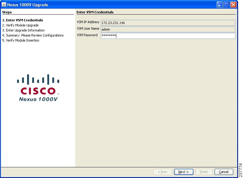
Nexus 1000v Upgrade: Enter VSM Credentials
Step 5
The Verify Module Upgrade screen opens.
Figure 25
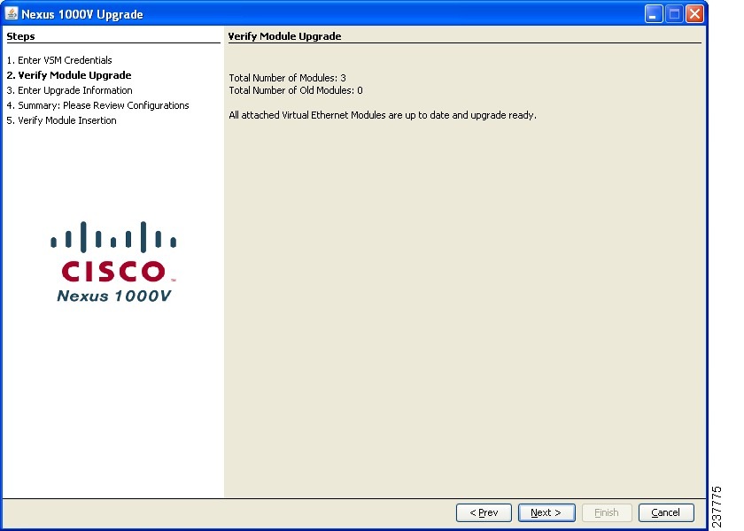
Nexus 1000v Upgrade: Verify Module Upgrade
Step 6
Step 7
Figure 26
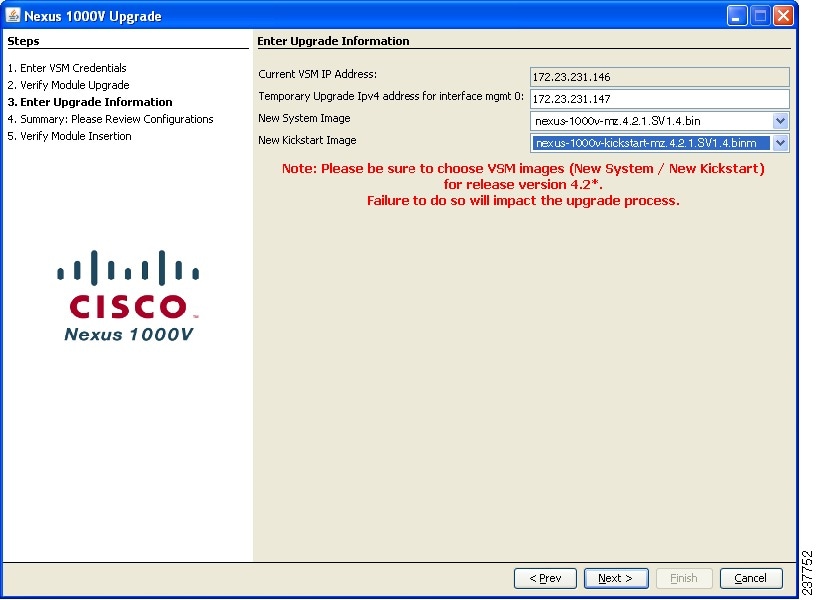
Nexus 1000v Upgrade: Enter Upgrade Information for L2
Step 8
a.
b.
c.
d.
e.
Figure 27
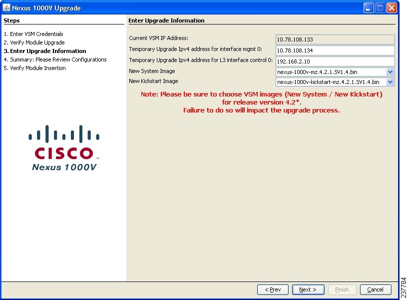
Nexus 1000v Upgrade: Enter Upgrade Information for L3
Step 9
a.
b.
c.
d.
e.
f.
If you have an L2 configuration, Figure 28 opens. If you have an L3 configuration, Figure 29 opens.
Figure 28

Nexus 1000v Upgrade: Layer 2 - Please Review Configurations
Figure 29
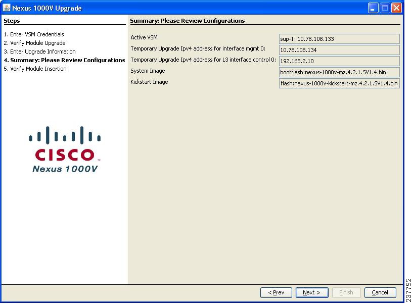
Nexus 1000v Upgrade: Layer 3 - Please Review Configurations
Step 10
The Upgrade Progress screen opens and the upgrade of the secondary VSM begins. Continue to Step 11.
Caution
Figure 30
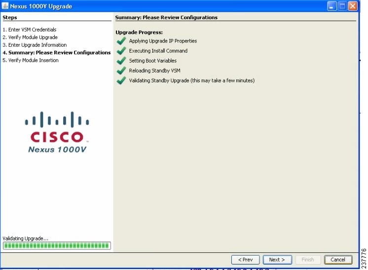
Nexus 1000V Upgrade: Secondary VSM Upgrade Progress
Note
Step 11
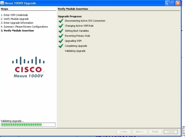
The Verify Module Insertion screen opens.
Figure 31
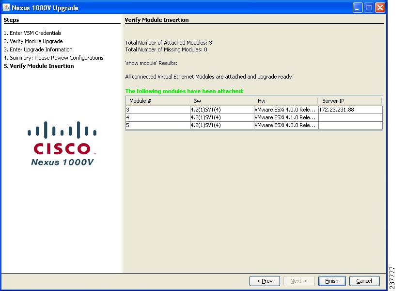
Nexus 1000v Upgrade: Verify Module Insertion
Step 12
a.
b.
–
–
vrf context managementip route 0.0.0.0/0 10.78.108.129ip route 192.168.1.0/24 192.168.2.1
Note
c.
VSM(config)# ip route 192.168.1.0/24 192.168.2.1VSM(config)# vrf context managementVSM(config-vrf)# no ip route 192.168.1.0/24 192.168.2.1
Caution
Step 13
If the module status is not "ok", refer to the Cisco Nexus 1000V Troubleshooting Guide, Release 4.2(1)SV1(4). Do not proceed unless all modules are in status "ok".
Step 14
Note
When finished, click Next.
Step 15
Step 16
Step 17
Step 18
•
•
–
The Verify Module Insertion window opens for the second VSM upgrade.
–
Figure 32
Nexus 1000v Upgrade: Second VSM Upgrade
Note
When the upgrade of the second VSM completes, the Summary screen opens.
Figure 33
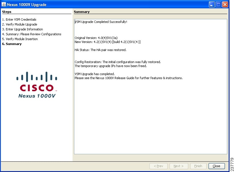
Nexus 1000v Upgrade: Summary
Step 19
The upgrade of the VSMs is complete.
Step 20
switch(config)# sho run | include vdcvdc N1KV-VSM id 1Step 21
switch(config)# vdc NIKV-VSM id 1switch(config-vdc)# limit-resource vlan minimum 16 maximum 2049The upgrade is complete.
Upgrading the VSMs Manually on a Cisco Nexus 1000V from Release 4.0(4)SV1(3, 3a, or 3b) to Release 4.2(1)SV1(4)
This section describes how to manually upgrade to Release 4.2(1)SV1(4) from Release 4.0(4)SV1(3, 3a, or 3b) by using the CLI.
Prerequisites to Upgrading the VSMs
The following are prerequisites to upgrading the VSMs:
•
•
•
•
Caution
•
•
•
•
•
•
Note
The two VSMs are identified as VSM1 and VSM2 which are the active and standby VSMs respectively.
To manually upgrade to Release 4.2(1)SV1(4), follow these steps:
Step 1
Step 2
switch# copy scp:root@192.0.2.13/N1K-VSM-images/nexus-1000v-mz.4.2.1.SV1.4.bin bootflash:
switch# copy scp:root@192.0.2.13/N1K-VSM-images/nexus-1000v-kickstart.mz.4.2.1.SV1.4.bin bootflash:
Step 3
switch# show module
Mod Ports Module-Type Model Status--- ----- -------------------------------- ------------------ ------------1 0 Virtual Supervisor Module Nexus1000V active *2 0 Virtual Supervisor Module Nexus1000V ha-standby3 248 Virtual Ethernet Module NA okMod Sw Hw--- --------------- ------1 4.0(4)SV1(3b) 0.02 4.0(4)SV1(3b) 0.03 4.2(1)SV1(4) VMware ESXi 4.1.0 Releasebuild-260247 (2.0) 1.9Mod MAC-Address(es) Serial-Num--- -------------------------------------- ----------1 00-19-07-6c-5a-a8 to 00-19-07-6c-62-a8 NA2 00-19-07-6c-5a-a8 to 00-19-07-6c-62-a8 NA3 02-00-0c-00-03-00 to 02-00-0c-00-03-80 NAMod Server-IP Server-UUID Server-Name--- ------------- ------------------------------------ --------------------1 172.23.233.64 NA NA2 172.23.233.64 NA NA3 172.23.232.72 33393935-3234-5553-4538-35314e323554 172.23.232.72* this terminal sessionswitch# show system redundancy status
bl-n1000v# show system redun statusRedundancy role---------------administrative: primaryoperational: primaryRedundancy mode---------------administrative: HAoperational: HAThis supervisor (sup-1)-----------------------Redundancy state: ActiveSupervisor state: ActiveInternal state: Active with HA standbyOther supervisor (sup-2)-----------------------Redundancy state: StandbySupervisor state: HA standbyInternal state: HA standbyStep 4
switch# show svs connectionsconnection vcenter:ip address: 192.0.2.10remote port: 80protocol: vmware-vim httpscertificate: defaultdatacenter name: sachinDCDVS uuid: 0c bf 0b 50 0b 4a b7 76-88 13 be 45 14 e8 9b 4econfig status: Enabledoperational status: Connectedsync status: Completeversion: VMware vCenter Server 4.0.0 build-208111
Step 5
Note
switch# configure terminal
Note
switch(config)# svs upgrade start mgmt0 ip ipaddr
WARNING!1. Please do not change the configuration of the system from this point onwards2. Ensure that all relevant ports, including uplinks, vmknics, and vsifs used for control, packet, management, storage as well as VSM ports, are all configured with system profiles3. Ensure there is network connectivity between VC, VSM pair, and the hosts/modules4. Ensure all the hosts/modules are upgraded with the next version of VEM software packageswitch(config)# end
Step 6
switch# install all system bootflash: nexus-1000v-mz.4.2.1.SV1.4.bin kickstart bootflash:nexus-1000v-kickstart-mz.4.2.1.SV1.4.bin
System image sync to standby is in progress...
System image is synced to standby.
Kickstart image sync to Standby is in progress...
Kickstart image is synced to standby.
Upgrade in process, hence Active boot variables are not updated.
Boot variables are updated to running configuration.
Step 7
switch# copy running-config startup-config
[########################################] 100%switch# show start | in boot
boot kickstart bootflash:/nexus-1000v-kickstart-mzg.4.0.4.SV1.3b.bin sup-1
boot system bootflash:/nexus-1000v-mzg.4.0.4.SV1.3b.bin sup-1
boot kickstart bootflash:/nexus-1000v-kickstart-mzg.4.2.1.SV1.4.bin sup-2
boot system bootflash:/nexus-1000v-mzg.4.2.1.SV1.4.bin sup-2
Note
Step 8
switch# reload module slot
This command will reboot standby supervisor module. (y/n)? [n] y2010 June 14 20:11:51 av1-vsm %PLATFORM-2-PFM_MODULE_RESET: Manual restart of Module 2 from Command Line Interfaceswitch# 2010 Jun 14 20:11:58 av1-vsm %PLATFORM-2-MOD_REMOVE: Module 2 removed (Serial number T50569A5039
Step 9
Step 10
switch# show system redundancy status
Redundancy role
---------------
administrative: standalone
operational: standalone
Redundancy mode
---------------
administrative: HA
operational: None
This supervisor (sup1)
----------------------
Redundancy state: Active
Supervisor state: Active
Internal state: Active with no standby
Other supervisor (sup-2)
------------------------
Redundancy State: Not present
Step 11
Caution
switch# show running-config
svs-domain
domain id 470
control vlan 233
packet vlan 233
svs mod L2
svs upgrade start mgmt0 ip 172.23.231.133.66
svs connection vc
protocol vmware-vimremote up address 172.23.231.133 port 80
vmware dvs uuid "0c bf 0e 50 0b 4a b7 76-88 13 be 45 14 e8 9b 4e" datacenter-name sachinDCconnectswitch# config t
switch# (config)# svs connection vc
switch# (config-svs-conn)# no connect
Step 12
switch(config-svs-conn)# end
switch(config)# end
switch# system redundancy role secondary
Setting will be activated on next reload
switch# show run | in boot
boot kickstart bootflash:/nexus-1000v-kickstart-mzg.4.0.4.SV1.3b.bin sup-1
boot system bootflash:/nexus-1000v-mzg.4.0.4.SV1.3b.bin sup-1
boot kickstart bootflash:/nexus-1000v-kickstart-mzg.4.2.1.SV1.4.bin sup-2
boot system bootflash:/nexus-1000v-mzg.4.2.1.SV1.4.bin sup-2
Step 13
switch# config t
Enter configuration commands, one per line. End with CNTL/Z.
switch(config)# boot kickstart bootflash:/nexus-1000v-kickstart-mz.4.2.1.SV1.4.bin
switch(config)# no boot system bootflash:/nexus-1000v.mzg.4.0.4.SV1.3b.bin sup-1
switch(config)# boot system bootflash:/nexus-1000v-mz.4.2.1.SV1.4.bin sup-1
switch(config)# end
switch# show run | in boot
boot kickstart bootflash:/nexus-1000v-kickstart-mzg.4.2.1.SV1.4.bin sup-1
boot system bootflash:/nexus-1000v-mzg.4.2.1.SV1.4.bin sup-1
boot kickstart bootflash:/nexus-1000v-kickstart-mzg.4.2.1.SV1.4.bin sup-2
boot system bootflash:/nexus-1000v-mzg.4.2.1.SV1.4.bin sup-2
Step 14
switch# copy running-config startup-config
[########################################] 100%
Step 15
switch# config t
Enter configuration commands, one per line. End with CNTL/Z.
switch(config)# show svs connect
connection vcenter:
ip address: 172.23.231.133
remote port: 80
protocol: vmware-vim https
certificate: default
datacenter name: n1000vDC
DVS uuid: 0c bf 0b 50 0b 4a b7 76-88 13 be 45 14 e8 9b 4e
config status: Enabled
operational status: Disconnected
sync status: -
version: -
Step 16
a.
b.
–
–
vrf context managementip route 0.0.0.0/0 10.78.108.129ip route 192.168.1.0/24 192.168.2.1
Note
c.
VSM(config)# ip route 192.168.1.0/24 192.168.2.1VSM(config)# vrf context managementVSM(config-vrf)# no ip route 192.168.1.0/24 192.168.2.1
Caution
Step 17
If the module status is not "ok", refer to the Cisco Nexus 1000V Troubleshooting Guide, Release 4.2(1)SV1(4). Do not proceed unless all modules are in status "ok".
Step 18
Note
switch# config t
Enter configuration commands, one per line. End with CNTL/Z.
switch(config)# svs upgrade complete
Warning: Config saved but not pushed to vCenter Server due to inactive connection!
switch(config)# end
switch# show run | in svs
svs-domain
svs mode L2
svs upgrade complete
svs connection vc
switch# config t
Enter configuration commands, one per line. End with CNTL/Z.
switch(config)# svs connection name
switch(config-svs-conn)# connect
switch(config-svs-conn)# end
switch(config)# end
switch# show module
Mod Ports Module-Type Model Status--- ----- -------------------------------- ------------------ ------------1 0 Virtual Supervisor Module Nexus1000V active *3 248 Virtual Ethernet Module NA okMod Sw Hw--- --------------- ------1 4.2(1)SV1(3b) 0.03 4.2(1)SV1(4) VMware ESXi 4.0.0 Releasebuild-208167 (1.9)1.9Mod MAC-Address(es) Serial-Num--- -------------------------------------- ----------1 00-19-07-6c-5a-a8 to 00-19-07-6c-62-a8 NA3 02-00-0c-00-03-00 to 02-00-0c-00-03-80 NAMod Server-IP Server-UUID Server-Name--- ------------- ------------------------------------ --------------------1 172.23.233.64 NA NA3 172.23.232.72 33393935-3234-5553-4538-35314e323554 sfish-srvr-72* this terminal session
Step 19
switch# system redundancy role primary
Step 20
switch# show module
switch# show run int mgmt0
!Command: show running-config interface mgmt0
!Time: Mon Jun 14 20:27:27 2010
version 4.2(1)SV1(4)
interface mgmt0
ip address 192.0.2.11/24
switch# reload
This command will reboot the system. (y/n)? [n] yswitch# copy running-config startup-config
switch# reload
Step 21
switch# show run int mgmt0
switch# config t
switch(config)# int mgmt0
switch(config-if)# ip address 192.0.2.11 255.255.255.0
Step 22
switch# show system redundancy status
Redundancy role---------------administrative: primaryoperational: primaryRedundancy mode---------------administrative: HAoperational: NoneThis supervisor (sup-1)-----------------------Redundancy state: ActiveSupervisor state: ActiveInternal state: Active with HA standbyOther supervisor (sup-2)-----------------------Redundancy state: StandbySupervisor state: HA standbyInternal state: HA standbyStep 23
switch# copy running-config startup-config[########################################] 100%
Upgrading the VSMs Manually on a Cisco Nexus 1010 from Release 4.0(4)SV1(3, 3a, or 3b) to Release 4.2(1)SV1(4)
This section describes the VSM manual upgrade procedure from Release 4.0(4)SV1(3, 3a, or 3b) to Release 4.2(1)SV1(4).
Prerequisites to Upgrading the VSMs
The following are prerequisites to upgrading the VSMs:
•
•
•
•
Caution
•
•
•
•
•
Note
This procedure is performed by the network administrator.
The two VSMs are identified as VSM1 and VSM2 which are the active and standby VSMs respectively.
To perform a manual upgrade to Release 4.2(1)SV1(4), follow these steps:
Step 1
Step 2
switch# copy scp://root@192.0.2.13/N1K-VSM-images/nexus-1000v-mz.4.2.1.SV1.4.bin
bootflash:
Enter vrf (If no input, current vrf 'default' is considered):root@192.0.2.13's password:nexus-1000v-mz.4.2.1.SV1.4.bin 100% 20MB 1.1MB/s 00:19switch#switch# copy scp://root@192.0.2.13/N1K-VSM-images/nexus-1000v-kickstart-mz.4.2.1.SV1.4.bin bootflash:Enter vrf (If no input, current vrf 'default' is considered):root@192.0.2.13's password:nexus-1000v-kickstart-mz.4.2.1.SV1.4.bin 100% 20MB 1.1MB/s 00:19switch#Step 3
switch# show moduleswitch# show moduleMod Ports Module-Type Model Status--- ----- -------------------------------- ------------------ ------------1 0 Virtual Supervisor Module Nexus1000V ha-standby2 0 Virtual Supervisor Module Nexus1000V active *3 248 Virtual Ethernet Module NA okMod Sw Hw--- --------------- ------1 4.0(4)SV1(3) 0.02 4.0(4)SV1(3) 0.03 4.2(1)SV1(4) 1.9Mod MAC-Address(es) Serial-Num--- -------------------------------------- ----------1 00-19-07-6c-5a-a8 to 00-19-07-6c-62-a8 NA2 00-19-07-6c-5a-a8 to 00-19-07-6c-62-a8 NA3 02-00-0c-00-03-00 to 02-00-0c-00-03-80 NAMod Server-IP Server-UUID Server-Name--- --------------- ------------------------------------ --------------------1 192.0.2.11 NA NA2 192.0.2.11 NA NA3 10.78.109.51 4220900d-76d3-89c5-17d7-b5a7d1a2487f 10.78.109.51switch# show system redundancy statusRedundancy role---------------administrative: secondaryoperational: secondaryRedundancy mode---------------administrative: HAoperational: HAThis supervisor (sup-2)-----------------------Redundancy state: ActiveSupervisor state: ActiveInternal state: Active with HA standbyOther supervisor (sup-1)------------------------Redundancy state: StandbySupervisor state: HA standbyInternal state: HA standbyStep 4
switch# show svs connectionsconnection vcenter:ip address: 192.0.2.10remote port: 80protocol: vmware-vim httpscertificate: defaultdatacenter name: SWAMYDVS uuid: 5e ca 20 50 bc 28 07 fb-0b 1d 98 56 40 cb fd 85config status: Enabledoperational status: Connectedsync status: Completeversion: VMware vCenter Server 4.0.0 build-258672Step 5
If you are using Layer 3 mode with control0, go to Step 6.
Note
switch# configure terminal
Note
switch(config)# svs upgrade start mgmt0 ip ipaddrWARNING!1. Please do not change the configuration of the system from this point onwards2. Ensure that all relevant ports, including uplinks, vmknics, and vsifs used for control, packet, management, storage as well as VSM ports, are all configured with system profiles3. Ensure there is network connectivity between VC, VSM pair, and the hosts/modules4. Ensure all the hosts/modules are upgraded with the next version of VEM software packageswitch(config)# endGo to Step 7.
Step 6
switch(config)# svs upgrade start mgmt0 ip ipaddr control0 ip ipaddrWARNING!1. Please do not change the configuration of the system from this point onwards2. Ensure that all relevant ports, including uplinks, vmknics, and vsifs used for control, packet, management, storage as well as VSM ports, are all configured with system profiles3. Ensure there is network connectivity between VC, VSM pair, and the hosts/modules4. Ensure all the hosts/modules are upgraded with the next version of VEM software packageswitch(config)# endStep 7
switch# install all system bootflash:nexus-1000v-mz.4.2.1.SV1.4.bin kickstart
bootflash:nexus-1000v-kickstart-mz.4.2.1.SV1.4.bin
System image sync to standby is in progress...System image is synced to standby.Kickstart image sync to Standby is in progress...Kickstart image is synced to standby.Upgrade in progress, hence Active boot variables are not updated.Boot variables are updated to running configuration.Step 8
switch# copy running-config startup-config[########################################] 100%switch# show startup-config | in bootboot kickstart bootflash:/nexus-1000v-kickstart-mz.4.2.1.SV1.4.bin sup-1boot system bootflash:/nexus-1000v-mz.4.2.1.SV1.4.bin sup-1boot kickstart bootflash:/nexus-1000v-kickstart-mz.4.0.4.SV1.3.bin sup-2boot system bootflash:/nexus-1000v-mz.4.0.4.SV1.3.bin sup-2
Note
Step 9
switch# reload module slotThis command will reboot standby supervisor module. (y/n)? [n] yabout to reset standby supswitch# 2011 Jan 7 14:07:38 switch %$ VDC-1 %$ %PLATFORM-2-PFM_MODULE_RESET: Manual restart of Module 1 from Command Line Interface2011 Jan 7 14:07:46 switch %$ VDC-1 %$ %PLATFORM-2-MOD_REMOVE: Module 1 removed (Serial number T023D73E802)Step 10
Step 11
switch# show system redundancy statusRedundancy role---------------administrative: standaloneoperational: standaloneRedundancy mode---------------administrative: HAoperational: NoneThis supervisor (sup1)----------------------Redundancy state: ActiveSupervisor state: ActiveInternal state: Active with no standbyOther supervisor (sup-2)------------------------Redundancy State: Not presentStep 12
switch# config tEnter configuration commands, one per line. End with CNTL/Z.switch(config)# no boot kickstart bootflash:/nexus-1000v-kickstart-mz.4.0.4.SV1.3.bin sup-2switch(config)# no boot system bootflash:/nexus-1000v-mz.4.0.4.SV1.3.bin sup-2switch(config)# boot kickstart bootflash:/nexus-1000v-kickstart-mz.4.2.1.SV1.4.bin sup-2switch(config)# boot system bootflash:/nexus-1000v-mz.4.2.1.SV1.4.bin sup-2switch(config)# endswitch# show running-config | in bootboot kickstart bootflash:/nexus-1000v-kickstart-mz.4.2.1.SV1.4.bin sup-1boot system bootflash:/nexus-1000v-mz.4.2.1.SV1.4.bin sup-1boot kickstart bootflash:/nexus-1000v-kickstart-mz.4.2.1.SV1.4.bin sup-2boot system bootflash:/nexus-1000v-mz.4.2.1.SV1.4.bin sup-2Step 13
switch# copy running-config startup-config[########################################] 100%Step 14
switch# show running-configsvs-domaindomain id 1291control vlan 1291packet vlan 1292svs mode L2svs upgrade start mgmt0 ip 192.0.2.12svs connection vcenterprotocol vmware-vimremote ip address 192.0.2.10 port 80vmware dvs uuid "5e ca 20 50 bc 28 07 fb-0b 1d 98 56 40 cb fd 85" datacenter-name SWAMYconnectswitch# config tswitch# (config)# svs connection nameswitch# (config-svs-conn)# no connectStep 15
VSM1 is running a release prior to Release 4.2(1)SV1(4).
switch# (config-svs-conn)# endswitch# (config)# endswitch# system redundancy role secondaryStep 16
switch# config tEnter configuration commands, one per line. End with CNTL/Z.switch(config)# no boot kickstart bootflash:/nexus-1000v-kickstart-mz.4.0.4.SV1.3.bin sup-2switch(config)# no boot system bootflash:/nexus-1000v-mz.4.0.4.SV1.3.bin sup-2switch(config)# boot kickstart bootflash:/nexus-1000v-kickstart-mz.4.2.1.SV1.4.bin sup-2switch(config)# boot system bootflash:/nexus-1000v-mz.4.2.1.SV1.4.bin sup-2switch(config)# endswitch# show running-config | in bootboot kickstart bootflash:/nexus-1000v-kickstart-mz.4.2.1.SV1.4.bin sup-1boot system bootflash:/nexus-1000v-mz.4.2.1.SV1.4.bin sup-1boot kickstart bootflash:/nexus-1000v-kickstart-mz.4.2.1.SV1.4.bin sup-2boot system bootflash:/nexus-1000v-mz.4.2.1.SV1.4.bin sup-2Step 17
switch# copy running-config startup-config[########################################] 100%Step 18
switch(config)# show svs connectionsconnection vcenter:ip address: 192.0.2.10remote port: 80protocol: vmware-vim httpscertificate: defaultdatacenter name: DC1DVS uuid: 5e ca 20 50 bc 28 07 fb-0b 1d 98 56 40 cb fd 85config status: Disabledoperational status: Disconnectedsync status: -version: -Step 19
a.
b.
–
–
vrf context managementip route 0.0.0.0/0 10.78.108.129ip route 192.168.1.0/24 192.168.2.1
Note
c.
VSM(config)# ip route 192.168.1.0/24 192.168.2.1VSM(config)# vrf context managementVSM(config-vrf)# no ip route 192.168.1.0/24 192.168.2.1
Caution
Step 20
If the module status is not ok, refer to the Cisco Nexus 1000V Troubleshooting Guide, Release 4.2(1)SV1(4). Do not proceed unless all modules are in status ok.
Step 21
Note
switch(config)# svs upgrade completeWarning: Config saved but not pushed to vCenter Server due to inactive connection!switch(config)# show running-config | in svssvs-domainsvs mode L2svs upgrade completesvs connection vcenterswitch(config)# svs connection nameswitch(config-svs-conn)# connectswitch(config-svs-conn)# endswitch# show moduleMod Ports Module-Type Model Status--- ----- -------------------------------- ------------------ ------------1 0 Virtual Supervisor Module Nexus1000V active *3 248 Virtual Ethernet Module NA okMod Sw Hw--- ---------------- ------------------------------------------------1 4.2(1)SV1(4) 0.03 4.2(1)SV1(4) VMware ESX 4.0.0 Releasebuild-208167 (1.9)Mod MAC-Address(es) Serial-Num--- -------------------------------------- ----------1 00-19-07-6c-5a-a8 to 00-19-07-6c-62-a8 NA3 02-00-0c-00-04-00 to 02-00-0c-00-04-80 NAMod Server-IP Server-UUID Server-Name--- --------------- ------------------------------------ --------------------1 192.0.2.12 NA NA3 10.78.109.51 4220900d-76d3-89c5-17d7-b5a7d1a2487f ESX40U1COS* this terminal sessionStep 22
switch# system redundancy role primaryStep 23
switch# show moduleMod Ports Module-Type Model Status--- ----- -------------------------------- ------------------ ------------2 0 Virtual Supervisor Module Nexus1000V active *Mod Sw Hw--- --------------- ------2 4.0(4)SV1(3) 0.0Mod MAC-Address(es) Serial-Num--- -------------------------------------- ----------2 00-19-07-6c-5a-a8 to 00-19-07-6c-62-a8 NAMod Server-IP Server-UUID Server-Name--- --------------- ------------------------------------ --------------------2 192.0.2.11 NA NAswitch# reloadThis command will reboot the system. (y/n)? [n] y2011 Jan 7 18:07:11 switch %$ VDC-1 %$ %PLATFORM-2-PFM_SYSTEM_RESET: Manual system restart from Command Line InterfaceStep 24
switch# show run int mgmt0switch# config tswitch(config)# int mgmt0switch(config-if)# ip address 192.0.2.11 255.255.255.240switch(config-if)# endStep 25
switch# show system redundancy statusRedundancy role---------------administrative: primaryoperational: primaryRedundancy mode---------------administrative: HAoperational: HAThis supervisor (sup-1)-----------------------Redundancy state: ActiveSupervisor state: ActiveInternal state: Active with HA standbyOther supervisor (sup-2)------------------------Redundancy state: StandbySupervisor state: HA standbyInternal state: HA standbyswitch# show moduleMod Ports Module-Type Model Status--- ----- -------------------------------- ------------------ ------------1 0 Virtual Supervisor Module Nexus1000V active *2 0 Virtual Supervisor Module Nexus1000V ha-standby3 248 Virtual Ethernet Module NA okMod Sw Hw--- ---------------- ------------------------------------------------1 4.2(1)SV1(4) 0.02 4.2(1)SV1(4) 0.03 4.2(1)SV1(4) VMware ESX 4.0.0 Releasebuild-208167 (1.9)Mod MAC-Address(es) Serial-Num--- -------------------------------------- ----------1 00-19-07-6c-5a-a8 to 00-19-07-6c-62-a8 NA2 00-19-07-6c-5a-a8 to 00-19-07-6c-62-a8 NA3 02-00-0c-00-04-00 to 02-00-0c-00-04-80 NAMod Server-IP Server-UUID Server-Name--- --------------- ------------------------------------ --------------------1 192.0.2.11 NA NA2 192.0.2.11 NA NA3 10.78.109.51 4220900d-76d3-89c5-17d7-b5a7d1a2487f 10.78.109.51* this terminal sessionStep 26
switch# copy running-config startup-config[########################################] 100%
Upgrading the VSMs Manually on a Cisco Nexus 1000V from Release 4.0(4)SV1(3, 3a, or 3b) to Release 4.2(1)SV1(4)
This section describes how to manually upgrade to Release 4.2(1)SV1(4) from Release 4.0(4)SV1(3, 3a, or 3b) by using the CLI.
Prerequisites to Upgrading the VSMs
The following are prerequisites to upgrading the VSMs:
•
•
•
•
Caution
•
•
•
•
•
•
Note
The two VSMs are identified as VSM1 and VSM2 which are the active and standby VSMs respectively.
To manually upgrade to Release 4.2(1)SV1(4), follow these steps:
Step 1
Step 2
switch# copy scp:root@192.0.2.13/N1K-VSM-images/nexus-1000v-mz.4.2.1.SV1.4.bin bootflash:
switch# copy scp:root@192.0.2.13/N1K-VSM-images/nexus-1000v-kickstart.mz.4.2.1.SV1.4.bin bootflash:
Step 3
switch# show module
Mod Ports Module-Type Model Status--- ----- -------------------------------- ------------------ ------------1 0 Virtual Supervisor Module Nexus1000V active *2 0 Virtual Supervisor Module Nexus1000V ha-standby3 248 Virtual Ethernet Module NA okMod Sw Hw--- --------------- ------1 4.0(4)SV1(3b) 0.02 4.0(4)SV1(3b) 0.03 4.2(1)SV1(4) VMware ESXi 4.1.0 Releasebuild-260247 (2.0) 1.9Mod MAC-Address(es) Serial-Num--- -------------------------------------- ----------1 00-19-07-6c-5a-a8 to 00-19-07-6c-62-a8 NA2 00-19-07-6c-5a-a8 to 00-19-07-6c-62-a8 NA3 02-00-0c-00-03-00 to 02-00-0c-00-03-80 NAMod Server-IP Server-UUID Server-Name--- ------------- ------------------------------------ --------------------1 172.23.233.64 NA NA2 172.23.233.64 NA NA3 172.23.232.72 33393935-3234-5553-4538-35314e323554 172.23.232.72* this terminal sessionswitch# show system redundancy status
bl-n1000v# show system redun statusRedundancy role---------------administrative: primaryoperational: primaryRedundancy mode---------------administrative: HAoperational: HAThis supervisor (sup-1)-----------------------Redundancy state: ActiveSupervisor state: ActiveInternal state: Active with HA standbyOther supervisor (sup-2)-----------------------Redundancy state: StandbySupervisor state: HA standbyInternal state: HA standbyStep 4
switch# show svs connectionsconnection vcenter:ip address: 172.23.231.133remote port: 80protocol: vmware-vim httpscertificate: defaultdatacenter name: sachinDCDVS uuid: 0c bf 0b 50 0b 4a b7 76-88 13 be 45 14 e8 9b 4econfig status: Enabledoperational status: Connectedsync status: Completeversion: VMware vCenter Server 4.0.0 build-208111
Step 5
If you are using L3 mode with control0, go to Step 6.
Note
switch# configure terminal
Note
switch(config)# svs upgrade start mgmt0 ip ipaddr
WARNING!1. Please do not change the configuration of the system from this point onwards2. Ensure that all relevant ports, including uplinks, vmknics, and vsifs used for control, packet, management, storage as well as VSM ports, are all configured with system profiles3. Ensure there is network connectivity between VC, VSM pair, and the hosts/modules4. Ensure all the hosts/modules are upgraded with the next version of VEM software packageswitch(config)# end
Step 6
switch# install all system bootflash: nexus-1000v-mz.4.2.1.SV1.4.bin kickstart bootflash:nexus-1000v-kickstart-mz.4.2.1.SV1.4.bin
System image sync to standby is in progress...
System image is synced to standby.
Kickstart image sync to Standby is in progress...
Kickstart image is synced to standby.
Upgrade in process, hence Active boot variables are not updated.
Boot variables are updated to running configuration.
Step 7
switch# copy running-config startup-config
[########################################] 100%switch# show start | in boot
boot kickstart bootflash:/nexus-1000v-kickstart-mzg.4.0.4.SV1.3b.bin sup-1
boot system bootflash:/nexus-1000v-mzg.4.0.4.SV1.3b.bin sup-1
boot kickstart bootflash:/nexus-1000v-kickstart-mzg.4.2.1.SV1.4.bin sup-2
boot system bootflash:/nexus-1000v-mzg.4.2.1.SV1.4.bin sup-2
Note
Step 8
switch# reload module slot
This command will reboot standby supervisor module. (y/n)? [n] y2010 June 14 20:11:51 av1-vsm %PLATFORM-2-PFM_MODULE_RESET: Manual restart of Module 2 from Command Line Interfaceswitch# 2010 Jun 14 20:11:58 av1-vsm %PLATFORM-2-MOD_REMOVE: Module 2 removed (Serial number T50569A5039
Step 9
Step 10
switch# show system redundancy status
Redundancy role
---------------
administrative: standalone
operational: standalone
Redundancy mode
---------------
administrative: HA
operational: None
This supervisor (sup1)
----------------------
Redundancy state: Active
Supervisor state: Active
Internal state: Active with no standby
Other supervisor (sup-2)
------------------------
Redundancy State: Not present
Step 11
switch# show running-config
svs-domain
domain id 470
control vlan 233
packet vlan 233
svs mod L2
svs upgrade start mgmt0 ip 192.0.2.12
svs connection vc
protocol vmware-vimremote up address 192.0.2.10 port 80
vmware dvs uuid "0c bf 0e 50 0b 4a b7 76-88 13 be 45 14 e8 9b 4e" datacenter-name sachinDCconnectswitch# config t
switch# (config)# svs connection vc
switch# (config-svs-conn)# no connect
Step 12
switch(config-svs-conn)# end
switch(config)# end
switch# system redundancy role secondary
Setting will be activated on next reload
switch# show run | in boot
boot kickstart bootflash:/nexus-1000v-kickstart-mzg.4.0.4.SV1.3b.bin sup-1
boot system bootflash:/nexus-1000v-mzg.4.0.4.SV1.3b.bin sup-1
boot kickstart bootflash:/nexus-1000v-kickstart-mzg.4.2.1.SV1.4.bin sup-2
boot system bootflash:/nexus-1000v-mzg.4.2.1.SV1.4.bin sup-2
Step 13
switch# config t
Enter configuration commands, one per line. End with CNTL/Z.
switch(config)# boot kickstart bootflash:/nexus-1000v-kickstart-mz.4.2.1.SV1.4.bin
switch(config)# no boot system bootflash:/nexus-1000v.mzg.4.0.4.SV1.3b.bin sup-1
switch(config)# boot system bootflash:/nexus-1000v-mz.4.2.1.SV1.4.bin sup-1
switch(config)# end
switch# show run | in boot
boot kickstart bootflash:/nexus-1000v-kickstart-mzg.4.2.1.SV1.4.bin sup-1
boot system bootflash:/nexus-1000v-mzg.4.2.1.SV1.4.bin sup-1
boot kickstart bootflash:/nexus-1000v-kickstart-mzg.4.2.1.SV1.4.bin sup-2
boot system bootflash:/nexus-1000v-mzg.4.2.1.SV1.4.bin sup-2
Step 14
switch# copy running-config startup-config
[########################################] 100%
Step 15
switch# config t
Enter configuration commands, one per line. End with CNTL/Z.
switch(config)# show svs connect
connection vcenter:
ip address: 192.0.2.10
remote port: 80
protocol: vmware-vim https
certificate: default
datacenter name: n1000vDC
DVS uuid: 0c bf 0b 50 0b 4a b7 76-88 13 be 45 14 e8 9b 4e
config status: Enabled
operational status: Disconnected
sync status: -
version: -
Step 16
a.
b.
–
–
vrf context managementip route 0.0.0.0/0 10.78.108.129ip route 192.168.1.0/24 192.168.2.1
Note
c.
VSM(config)# ip route 192.168.1.0/24 192.168.2.1VSM(config)# vrf context managementVSM(config-vrf)# no ip route 192.168.1.0/24 192.168.2.1
Caution
Step 17
If the module status is not ok, refer to the Cisco Nexus 1000V Troubleshooting Guide, Release 4.2(1)SV1(4). Do not proceed unless all modules are in status ok.
Step 18
Note
switch# config t
Enter configuration commands, one per line. End with CNTL/Z.
switch(config)# svs upgrade complete
Warning: Config saved but not pushed to vCenter Server due to inactive connection!
switch(config)# end
switch# show run | in svs
svs-domain
svs mode L2
svs upgrade complete
svs connection vc
switch# config t
Enter configuration commands, one per line. End with CNTL/Z.
switch(config)# svs connection name
switch(config-svs-conn)# connect
switch(config-svs-conn)# end
switch(config)# end
switch# show module
Mod Ports Module-Type Model Status--- ----- -------------------------------- ------------------ ------------1 0 Virtual Supervisor Module Nexus1000V active *3 248 Virtual Ethernet Module NA okMod Sw Hw--- --------------- ------1 4.2(1)SV1(3b) 0.03 4.2(1)SV1(4) VMware ESXi 4.0.0 Releasebuild-208167 (1.9)1.9Mod MAC-Address(es) Serial-Num--- -------------------------------------- ----------1 00-19-07-6c-5a-a8 to 00-19-07-6c-62-a8 NA3 02-00-0c-00-03-00 to 02-00-0c-00-03-80 NAMod Server-IP Server-UUID Server-Name--- ------------- ------------------------------------ --------------------1 172.23.233.64 NA NA3 172.23.232.72 33393935-3234-5553-4538-35314e323554 sfish-srvr-72* this terminal session
Step 19
switch# system redundancy role primary
Step 20
switch# show module
switch# show run int mgmt0
!Command: show running-config interface mgmt0
!Time: Mon Jun 14 20:27:27 2010
version 4.2(1)SV1(4)
interface mgmt0
ip address 192.0.2.11/24
switch(config)# show version
switch# reload
This command will reboot the system. (y/n)? [n] yswitch# copy running-config startup-config
switch# reload
Step 21
switch# show run int mgmt0
switch# config t
switch(config)# int mgmt0
switch(config-if)# ip address 192.0.2.11 255.255.255.0
Step 22
switch# show system redundancy status
Redundancy role---------------administrative: primaryoperational: primaryRedundancy mode---------------administrative: HAoperational: NoneThis supervisor (sup-1)-----------------------Redundancy state: ActiveSupervisor state: ActiveInternal state: Active with HA standbyOther supervisor (sup-2)-----------------------Redundancy state: StandbySupervisor state: HA standbyInternal state: HA standby
Accepting the VEM Upgrade in the vCenter Client
This section describes the steps that a server administrator follows to accept a VEM upgrade in the vCenter Client and includes the following topics:
•
•
For details about how to upgrade the VEMs see "Upgrading the VEMs" section.
Prerequisites to Accepting the VEM Upgrade
The following are prerequisites to accepting a VEM upgrade:
•
•
•
•
Accepting the VEM Upgrade
The server administrator accepts the VEM upgrade after the network administrator has upgraded the VSM and notified vCenter server of the availability of the new VEM software version.
To accept a request for a VEM upgrade, follow these steps:
Note
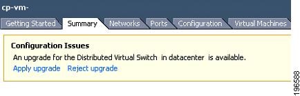
Step 1
Figure 34 vSphere Client DVS Summary Tab
Step 2
The following actions occur:
•
•
•
For details about the VEM upgrade performed by the network administrator, see the "Upgrading the VEMs" section.
Troubleshooting
This section provides some troubleshooting guidelines for problems that may occur during the Cisco Nexus 1000V upgrade process. This section includes the following topic:
•
Non-default (Jumbo) MTU Settings Symptoms and Solutions
Available Documents
This section lists the documents used with the Cisco Nexus 1000V and available on Cisco.com at the following url:
http://www.cisco.com/en/US/products/ps9902/tsd_products_support_series_home.html
General Information
Cisco Nexus 1000V Documentation Roadmap, Release 4.2(1)SV1(4)
Cisco Nexus 1000V Release Notes, Release 4.2(1)SV1(4)
Cisco Nexus 1000V Compatibility Information, Release 4.2(1)SV1(4)
Cisco Nexus 1010 Management Software Release Notes, Release 4.2(1)SP1(2)
Install and Upgrade
Cisco Nexus 1000V Virtual Supervisor Module Software Installation Guide, Release 4.2(1)SV1(4)
Cisco Nexus 1000V Software Upgrade Guide, Release 4.2(1)SV1(4)
Cisco Nexus 1000V VEM Software Installation and Upgrade Guide, Release 4.2(1)SV1(4)
Cisco Nexus 1010 Virtual Services Appliance Hardware Installation Guide
Cisco Nexus 1010 Software Installation and Upgrade Guide, Release 4.2(1)SP1(2)
Configuration Guides
Cisco Nexus 1000V License Configuration Guide, Release 4.2(1)SV1(4)
Cisco Nexus 1000V Getting Started Guide, Release 4.2(1)SV1(4)
Cisco Nexus 1000V High Availability and Redundancy Configuration Guide, Release 4.2(1)SV1(4)
Cisco Nexus 1000V Interface Configuration Guide, Release 4.2(1)SV1(4)
Cisco Nexus 1000V Layer 2 Switching Configuration Guide, Release 4.2(1)SV1(4)
Cisco Nexus 1000V Port Profile Configuration Guide, Release 4.2(1)SV1(4)
Cisco Nexus 1000V Quality of Service Configuration Guide, Release 4.2(1)SV1(4)
Cisco Nexus 1000V Security Configuration Guide, Release 4.2(1)SV1(4)
Cisco Nexus 1000V System Management Configuration Guide, Release 4.2(1)SV1(4)
Cisco Nexus 1010 Software Configuration Guide, Release 4.2(1)SP1(2)
Programming Guide
Cisco Nexus 1000V XML API User Guide, Release 4.2(1)SV1(4)
Reference Guides
Cisco Nexus 1000V Command Reference, Release 4.2(1)SV1(4)
Cisco Nexus 1000V MIB Quick Reference
Cisco Nexus 1010 Command Reference, Release 4.2(1)SP1(2)
Troubleshooting and Alerts
Cisco Nexus 1000V Troubleshooting Guide, Release 4.2(1)SV1(4)
Cisco Nexus 1000V Password Recovery Guide
Cisco NX-OS System Messages Reference
Virtual Security Gateway Documentation
Cisco Virtual Security Gateway for Nexus 1000V Series Switch Release Notes, Release 4.2(1)VSG(1)
Virtual Network Management Center
Release Notes for Cisco Virtual Network Management Center, Release 1.0.1
Cisco Virtual Network Management Center CLI Configuration Guide, Release 1.0.1
Cisco Virtual Network Management Center GUI Configuration Guide, Release 1.0.1
Cisco Virtual Network Management Center XML API Reference Guide, Release 1.0.1
Network Analysis Module Documentation
Cisco Network Analysis Module Software Documentation Guide, 4.2
Cisco Nexus 1000V NAM Virtual Service Blade Installation and Configuration Guide
Network Analysis Module Command Reference Guide, 4.2
User Guide for the Cisco Network Analysis Module Virtual Service Blades, 4.2
Cisco Network Analysis Module Software Release Notes, 4.2
Obtaining Documentation and Submitting a Service Request
For information on obtaining documentation, submitting a service request, and gathering additional information, see the monthly What's New in Cisco Product Documentation, which also lists all new and revised Cisco technical documentation, at:
http://www.cisco.com/en/US/docs/general/whatsnew/whatsnew.html
Subscribe to the What's New in Cisco Product Documentation as a Really Simple Syndication (RSS) feed and set content to be delivered directly to your desktop using a reader application. The RSS feeds are a free service and Cisco currently supports RSS Version 2.0.
This document is to be used in conjunction with the documents listed in the Available Documents section.
Cisco and the Cisco logo are trademarks or registered trademarks of Cisco and/or its affiliates in the U.S. and other countries. To view a list of Cisco trademarks, go to this URL: www.cisco.com/go/trademarks. Third-party trademarks mentioned are the property of their respective owners. The use of the word partner does not imply a partnership relationship between Cisco and any other company. (1110R)
Any Internet Protocol (IP) addresses and phone numbers used in this document are not intended to be actual addresses and phone numbers. Any examples, command display output, network topology diagrams, and other figures included in the document are shown for illustrative purposes only. Any use of actual IP addresses or phone numbers in illustrative content is unintentional and coincidental.
© 2011 Cisco Systems, Inc. All rights reserved.
 Feedback
Contact Cisco
- Open a Support Case

- (Requires a Cisco Service Contract)