Cisco IE 2000U Switch Hardware Installation Guide
Bias-Free Language
The documentation set for this product strives to use bias-free language. For the purposes of this documentation set, bias-free is defined as language that does not imply discrimination based on age, disability, gender, racial identity, ethnic identity, sexual orientation, socioeconomic status, and intersectionality. Exceptions may be present in the documentation due to language that is hardcoded in the user interfaces of the product software, language used based on RFP documentation, or language that is used by a referenced third-party product. Learn more about how Cisco is using Inclusive Language.
- Updated:
- June 2, 2015
Chapter: Troubleshooting
Troubleshooting
This section provides these topics for troubleshooting problems:
■![]() Finding the Switch Serial Number
Finding the Switch Serial Number
Diagnosing Problems
The switch LEDs provide troubleshooting information about the switch. They show boot fast failures, port-connectivity problems, and overall switch performance. You can also get statistics from the CLI or an SNMP workstation. See the Cisco Connected Grid Switches System Management Software Configuration Guide at www.cisco.com/go/ie2000u-docs or the documentation that came with your SNMP application for details. For command information, go to the Cisco IOS 15.2M&T command references at: http://www.cisco.com/en/US/products/ps11746/prod_command_reference_list.html
Switch Boot Fast
See the Verifying Switch Operation for information on boot fast.
Note: Boot fast failures are usually fatal. Contact your Cisco TAC representative if your switch does not successfully complete boot fast.
Note: You can disable boot fast and run POST by using the Cisco IOS CLI. See the Cisco Connected Grid Switches System Management Software Configuration Guide at www.cisco.com/go/ie2000u-docs and the Cisco IOS 15.2M&T command references at http://www.cisco.com/en/US/products/ps11746/prod_command_reference_list.html.
Switch LEDs
Look at the port LEDs information when troubleshooting the switch. See the LEDs for a description of the LED colors and their meanings.
Switch Connections
Bad or Damaged Cable
Always examine the cable for marginal damage or failure. A cable might be just good enough to connect at the physical layer, but it could corrupt packets as a result of subtle damage to the wiring or connectors. You can identify this problem because the port has many packet errors or it constantly flaps (loses and regains link).
■![]() Exchange the copper or fiber-optic cable with a known good cable.
Exchange the copper or fiber-optic cable with a known good cable.
■![]() Look for broken or missing pins on cable connectors.
Look for broken or missing pins on cable connectors.
■![]() Rule out any bad patch panel connections or media converters between the source and the destination. If possible, bypass the patch panel, or eliminate media converters (fiber-optic-to-copper).
Rule out any bad patch panel connections or media converters between the source and the destination. If possible, bypass the patch panel, or eliminate media converters (fiber-optic-to-copper).
■![]() Try the cable in another port to see if the problem follows the cable.
Try the cable in another port to see if the problem follows the cable.
Ethernet and Fiber-Optic Cables
Ensure that you have the correct cable:
■![]() For Ethernet, use Category 3 copper cable for 10 Mb/s UTP connections. Use either Category 5, Category 5e, or Category 6 UTP for 10/100 or 10/100/1000 Mb/s connections.
For Ethernet, use Category 3 copper cable for 10 Mb/s UTP connections. Use either Category 5, Category 5e, or Category 6 UTP for 10/100 or 10/100/1000 Mb/s connections.
■![]() Verify that you have the correct fiber-optic cable for the distance and port type. Make sure that the connected device ports match and use the same type encoding, optical frequency, and fiber type.
Verify that you have the correct fiber-optic cable for the distance and port type. Make sure that the connected device ports match and use the same type encoding, optical frequency, and fiber type.
■![]() Determine if a copper crossover cable was used when a straight-through was required or the reverse. Enable auto-MDIX on the switch, or replace the cable. See Table 11 for recommended Ethernet cables.
Determine if a copper crossover cable was used when a straight-through was required or the reverse. Enable auto-MDIX on the switch, or replace the cable. See Table 11 for recommended Ethernet cables.
Link Status
Verify that both sides have a link. A broken wire or a shutdown port can cause one side to show a link even though the other side does not have a link.
A port LED that is on does not guarantee that the cable is functional. It might have encountered physical stress, causing it to function at a marginal level. If the port LED does not turn on:
■![]() Connect the cable from the switch to a known good device.
Connect the cable from the switch to a known good device.
■![]() Ensure that both ends of the cable are connected to the correct ports.
Ensure that both ends of the cable are connected to the correct ports.
■![]() Verify that both devices have power.
Verify that both devices have power.
■![]() Verify that you are using the correct cable type. See Cables and Adapters for information.
Verify that you are using the correct cable type. See Cables and Adapters for information.
■![]() Look for loose connections. Sometimes a cable appears to be seated but is not. Disconnect the cable, and then reconnect it.
Look for loose connections. Sometimes a cable appears to be seated but is not. Disconnect the cable, and then reconnect it.
10/100 and 10/100/1000 Port Connections
If a port appears to malfunction:
■![]() Verify the status of all ports. See Table 8 for descriptions of the LEDs and their meanings.
Verify the status of all ports. See Table 8 for descriptions of the LEDs and their meanings.
■![]() Use the show interfaces privileged EXEC command to see if the port is error-disabled, disabled, or shut down. Reenable the port if necessary.
Use the show interfaces privileged EXEC command to see if the port is error-disabled, disabled, or shut down. Reenable the port if necessary.
■![]() Verify the cable type. See Cable and Connectors
Verify the cable type. See Cable and Connectors
SFP Module
Use only Cisco SFP modules. Each Cisco module has an internal serial EEPROM that is encoded with security information. This encoding verifies that the module meets the requirements for the switch.
■![]() Inspect the SFP module. Exchange the suspect module with a known good module.
Inspect the SFP module. Exchange the suspect module with a known good module.
■![]() Verify that the module is supported on this platform. (The switch release notes at www.cisco.com/go/ie2000u-docs list the SFP modules that the switch supports.)
Verify that the module is supported on this platform. (The switch release notes at www.cisco.com/go/ie2000u-docs list the SFP modules that the switch supports.)
■![]() Use the show interfaces privileged EXEC command to see if the port or module is error-disabled, disabled, or shut down. Reenable the port if needed.
Use the show interfaces privileged EXEC command to see if the port or module is error-disabled, disabled, or shut down. Reenable the port if needed.
■![]() Make sure that all fiber-optic connections are clean and securely connected.
Make sure that all fiber-optic connections are clean and securely connected.
Interface Settings
Verify that the interface is not disabled or powered off. If an interface is manually shut down on either side of the link, it does not come up until you reenable the interface. Use the show interfaces privileged EXEC command to see if the interface is error-disabled, disabled, or shut down on either side of the connection. If needed, reenable the interface.
Ping End Device
Ping from the directly connected switch first, and then work your way back port by port, interface by interface, trunk by trunk, until you find the source of the connectivity issue. Make sure that each switch can identify the end device MAC address in its Content-Addressable Memory (CAM) table.
Spanning Tree Loops
STP loops can cause serious performance issues that look like port or interface problems.
A unidirectional link can cause loops. It occurs when the traffic sent by the switch is received by the neighbor, but the traffic from the neighbor is not received by the switch. A broken cable, other cabling problems, or a port issue can cause this one-way communication.
You can enable UniDirectional Link Detection (UDLD) on the switch to help identify unidirectional link problems. For information about enabling UDLD on the switch, see the Cisco Layer 2 Switching Software Configuration Guide for Cisco IE 2000U and the documentation for Cisco Connected Grid Switches on Cisco.com.
Switch Performance
Speed, Duplex, and Autonegotiation
Port statistics that show a large amount of alignment errors, frame check sequence (FCS), or late-collisions errors, might mean a speed or duplex mismatch.
A common issue occurs when duplex and speed settings are mismatched between two switches, between a switch and a router, or between the switch and a workstation or server. Mismatches can happen when manually setting the speed and duplex or from autonegotiation issues between the two devices.
To maximize switch performance and to ensure a link, follow one of these guidelines when changing the duplex or the speed settings:
■![]() Let both ports autonegotiate both speed and duplex.
Let both ports autonegotiate both speed and duplex.
■![]() Manually set the speed and duplex parameters for the interfaces on both ends of the connection.
Manually set the speed and duplex parameters for the interfaces on both ends of the connection.
■![]() If a remote device does not autonegotiate, use the same duplex settings on the two ports. The speed parameter adjusts itself even if the connected port does not autonegotiate.
If a remote device does not autonegotiate, use the same duplex settings on the two ports. The speed parameter adjusts itself even if the connected port does not autonegotiate.
Autonegotiation and Network Interface Cards
Problems sometimes occur between the switch and third-party network interface cards (NICs). By default, the switch ports and interfaces autonegotiate. Laptops or other devices are commonly set to autonegotiate, yet sometimes issues occur.
To troubleshoot autonegotiation problems, try manually setting both sides of the connection. If this does not solve the problem, there could be a problem with the firmware or software on the NIC. You can resolve this by upgrading the NIC driver to the latest version.
Cabling Distance
If the port statistics show excessive FCS, late-collision, or alignment errors, verify that the cable distance from the switch to the connected device meets the recommended guidelines. See the Cables and Adapters.
Resetting the Switch
These are reasons why you might want to reset the switch to the factory default settings:
■![]() You installed the switch in your network and cannot connect to it because you assigned the wrong IP address.
You installed the switch in your network and cannot connect to it because you assigned the wrong IP address.
■![]() You want to reset the password on the switch.
You want to reset the password on the switch.
Note: Resetting the switch deletes the configuration and reboots the switch.
Caution: If you press the Express Setup button when you power on, the automatic boot sequence stops, and the switch enters bootloader mode.
1.![]() Power up the switch and wait a couple of minutes for it to boot up completely.
Power up the switch and wait a couple of minutes for it to boot up completely.
2.![]() Press and hold the Express Setup button for about 10 seconds.
Press and hold the Express Setup button for about 10 seconds.
The configuration is reset and the system reboots.
The switch now behaves like an unconfigured switch. You can configure the switch by using the CLI setup procedure described in Configuring the Switch with the CLI-Based Setup Program.
How to Recover Passwords
Password recovery is a feature that a system administrator can enable or disable. If password recovery is disabled, the only way to recover from a lost or forgotten password is to clear the switch configuration entirely.
Cisco Connected Grid Switches Security Software Configuration Guide provides details about disabling the password recovery feature. Cisco IOS Basics and File Management for Connected Grid Switches provides information about the procedure for recovering passwords.
Finding the Switch Serial Number
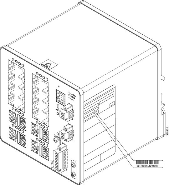
If you contact Cisco Technical Assistance, you need to know the serial number of your switch. The serial number is on the compliance label on the right-hand side of the switch. See Figure 49. You can also use the show version privileged EXEC command to obtain the switch serial number.
Figure 49 Serial Number Location for the Cisco IE 2000U Switches
 Feedback