Cisco IE 2000U Switch Hardware Installation Guide
Bias-Free Language
The documentation set for this product strives to use bias-free language. For the purposes of this documentation set, bias-free is defined as language that does not imply discrimination based on age, disability, gender, racial identity, ethnic identity, sexual orientation, socioeconomic status, and intersectionality. Exceptions may be present in the documentation due to language that is hardcoded in the user interfaces of the product software, language used based on RFP documentation, or language that is used by a referenced third-party product. Learn more about how Cisco is using Inclusive Language.
- Updated:
- June 2, 2015
Chapter: Overview
- Switch Models
- Front Panel
- 10/100BASE-T Ports
- Power over Ethernet Ports
- 10/100/1000BASE-T Ports
- 100 Mb/s SFP Module Slots
- 100/1000 Mb/s SFP Module Slots
- Dual-Purpose Fast Ethernet Ports
- Dual-Purpose Gigabit Ethernet Ports
- SFP Modules
- Power Connectors
- PoE Power Connector
- Alarm Connector
- Management Ports
- LEDs
- PoE Status LED
- Flash Memory Card
- Rear Panel
- Management Options
- Network Configurations
Product Overview
This section describes the Cisco IE 2000U Industrial Ethernet Switch (IE 2000U), hereafter referred to as the switch. The switch provides a Gigabit Ethernet aggregation and small form factor switch for the substation automation family of Connected Grid switches. It is suitable for Connected Energy applications such as grid automation, distributed generation, integrated renewable energy, trackside substations, and water applications.
You can connect these switches to devices such as servers, routers, and other switches. In connected grid environments, you can connect any Ethernet-enabled industrial communication devices, including field area routers (FARs), connected grid routers (CGRs), programmable logic controllers (PLCs), human-machine interfaces (HMIs), drives, sensors, video devices, traffic signal controllers, and intelligent electronic devices (IEDs).
You can mount the switch on a DIN rail in an industrial enclosure. Its components are designed to withstand extremes in temperature, vibration, and shock that are common in an industrial environment.
The Cisco IE 2000U Industrial Ethernet switch has six models, which are grouped according to five different port configurations. The IE 2000U-16TC-G-X model is the only model available with a conformal coating (Humiseal AR/UR UV40).
Note: The switch does not have cooling fans.
Switch Models
Table 1 describes the switch models.
Front Panel
This section describes the front panel components:
■![]() 4, 8, or 16 10/100BASE-T Ethernet ports.
4, 8, or 16 10/100BASE-T Ethernet ports.
■![]() Two 10/100/1000 ports (available on some models). See Table 1.
Two 10/100/1000 ports (available on some models). See Table 1.
■![]() Two or four dual-purpose ports (available on some models). See Table 1.
Two or four dual-purpose ports (available on some models). See Table 1.
■![]() Two or four SFP module slots (available on some models). See Table 1.
Two or four SFP module slots (available on some models). See Table 1.
■![]() Four PoE ports (available on some models). See Table 1.
Four PoE ports (available on some models). See Table 1.
Note: You can also configure the four PoE ports as PoE+ ports. The PoE ports require that a separate DC power source be connected to the switch (optional). The switch has a terminal block on its front panel to connect to a power supply module or to a site source.
■![]() USB mini-Type B (console) port
USB mini-Type B (console) port
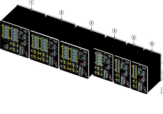
All of the switches have similar components. See Figure 1, Figure 2, Figure 3, Figure 4, Figure 5 and Figure 6 for examples.
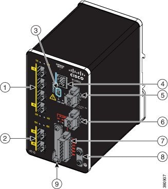
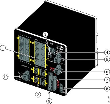
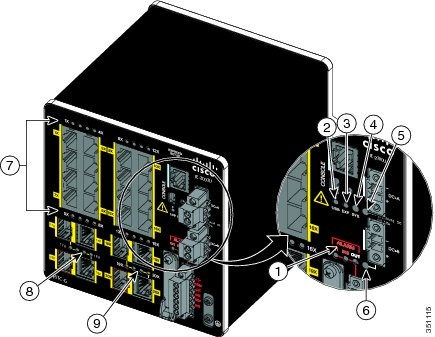
Figure 1 IE 2000U-4S-G Front Panel View
|
|
|
||
|
|
|
||
|
|
|
||
|
|
|
||
|
|
|
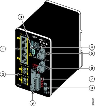
Figure 2 IE 2000U-4TS-G Front Panel View
|
|
|
||
|
|
|
||
|
|
|
||
|
|
|
||
|
|
|
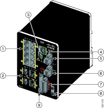
Figure 3 IE 2000U-8TC-G Front Panel View
|
|
|
||
|
|
|
||
|
|
|
||
|
|
|
||
|
|
|
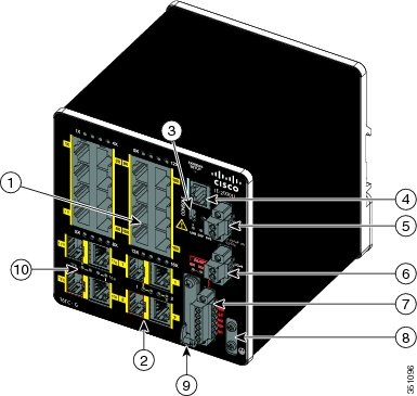
Figure 4 IE 2000U-16TC-G Front Panel View
|
|
|
||
|
|
|
||
|
|
|
||
|
|
|
||
|
|
|
Figure 5 IE 2000U-16TC-GP Front Panel View
|
|
|
||
|
|
|
||
|
|
|
||
|
|
|
||
|
|
|
Figure 6 IE 2000U Switches Front Panel View
|
|
|
||
|
|
IE 2000U-16TC-G-X1 |
|
|
|
|
|
10/100BASE-T Ports
You can set the 10/100BASE-T ports to operate at 10 or 100 Mb/s in full-duplex or half-duplex mode. You can also set these ports for speed and duplex autonegotiation in compliance with IEEE 802.3ab. (The default setting is autonegotiate.) When set for autonegotiation, the port senses the speed and duplex settings of the attached device and advertises its own capabilities. If the connected device also supports autonegotiation, the switch port negotiates the best connection (that is, the fastest line speed that both devices support, and full-duplex transmission if the attached device supports it) and configures itself accordingly. In all cases, the attached device must be within 328 feet (100 meters). 100BASE-TX traffic requires CAT5 cables or better. 10BASE-T traffic can use Category 3 cables or better.
When connecting the switch to workstations, servers, routers, and Cisco IP Phones, make sure that the cable is a straight-through cable.
You can use the mdix auto interface configuration command in the command-line interface (CLI) to enable the automatic medium-dependent interface crossover (auto-MDIX) feature. When the auto-MDIX feature is enabled, the switch detects the required cable type for copper Ethernet connections and configures the interfaces accordingly.
Power over Ethernet Ports
On the IE 2000U-16TC-GP model of the IE 2000U switch, four of the 10/100BASE-T ports are available as PoE ports. The four ports can operate either as PoE (IEEE 802.3af) ports or can be configured to operate as PoE+ (IEEE 802.at) ports. In order to operate 10/100 ports as PoE ports, a separate DC power source is required. For more information, see Connecting Power to the Switch PoE DC-Input (Optional).
10/100/1000BASE-T Ports
The IEEE 802.3u 10/100/1000BASE-T ports provide full-duplex 10, 100 or 1000 Mb/s connectivity over CAT5 unshielded twisted pair (UTP) copper cabling. The default setting is autonegotiate.
100 Mb/s SFP Module Slots
The IEEE 802.3u 100 Mb/s SFP module slots provide full-duplex 100 Mb/s connectivity over multi-mode (MM) fiber cables or single-mode (SM) fiber cables. These ports use a SFP fiber-optic transceiver module that accepts a dual local connector (LC). Check the SFP specifications for the cable type and length.
100/1000 Mb/s SFP Module Slots
The IEEE 802.3u 100/1000 Mb/s SFP module slots provide full-duplex 100 or 1000 Mb/s connectivity over multi-mode (MM) fiber cables or single-mode (SM) fiber cables. These ports use a SFP fiber-optic transceiver module that accepts a dual LC connector. Check the SFP specifications for the cable type and length.
Dual-Purpose Fast Ethernet Ports
You can configure the dual-purpose Fast Ethernet ports on the switch as either 10/100BASE-T ports or as 100 Mb/s SFP-module ports. You can set the 10/100BASE-T ports to autonegotiate, or you can configure them as fixed 10 or 100 Mb/s (Fast) Ethernet ports.
By default, the switch selects the medium for each dual-purpose port (10/100BASE-T or SFP). When a link is achieved on one media type, the switch disables the other media type until the active link goes down. If links are active on both media, the SFP-module port has priority, but you can use the media-type interface configuration command to manually designate the port as an RJ-45 port or an SFP port.
You can configure the speed and duplex settings consistent with the selected media type. For information on configuring interfaces, see the Cisco Connected Grid Switches Interfaces Software Configuration Guide.
Dual-Purpose Gigabit Ethernet Ports
You can configure the dual-purpose Gigabit Ethernet ports on the switch as either 10/1001000BASE-T ports or as 100/1000 Mb/s SFP-module ports. You can set the 10/100/1000BASE-T ports to autonegotiate, or you can configure them as fixed 10, 100, or 1000 Mb/s (Gigabit) Ethernet ports.
By default, the switch selects the medium for each dual-purpose port (10/100/1000BASE-T or SFP). When a link is achieved on one media type, the switch disables the other media type until the active link goes down. If links are active on both media, the SFP-module port has priority, but you can use the media-type interface configuration command to manually designate the port as an RJ-45 port or an SFP port.
You can configure the speed and duplex settings consistent with the selected media type. For information on configuring interfaces, see the Cisco Connected Grid Switches Interfaces Software Configuration Guide.
SFP Modules
The switch Ethernet SFP modules provide connections to other devices. These field-replaceable transceiver modules provide the uplink interfaces. The modules have LC connectors for fiber-optic connections or RJ-45 connectors for copper connections. You can use any combination of the supported SFP modules listed in Table 2.
|
|
|
|---|---|
For minimum software requirements, refer to the Release Notes for your platform.
For the most up-to-date list of supported SFP models for Cisco Industrial Ethernet switches, see http://www.cisco.com/en/US/docs/interfaces_modules/transceiver_modules/compatibility/matrix/OL_6981.html#wp138176
For information about SFP modules, see your SFP module documentation and the Installing SFP Modules into SFP Module Slots. For cable specifications, see SFP Module Cables.
Power Connectors
You connect the DC power to the switch through the front panel connectors. The switch has a dual-feed DC power supply; two connectors provide primary and secondary DC power (DC-A and DC-B). The DC power connectors are near the top right of the front panel. See Figure 1. Each power connector has an LED status indicator.
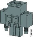
The switch power connectors are attached to the switch chassis. Each power connector has screw terminals for terminating the DC power (see Figure 7). All connectors are attached to the switch front panel with the provided captive screws.
The power connector labeling is on the panel. The positive DC power connection is labeled “ +”, and the return connection is labeled “ –”.
The switch can operate with a single power source or with dual power sources. When both power sources are operational, the switch draws power from the DC source with the higher voltage. If one of the two power sources fails, the other continues to power the switch.
In systems configured with the redundant power option, connect each of the two power supplies to separate independent power sources. If you fail to do this, your system might be susceptible to total power failure due to a fault in the external wiring or a tripped circuit breaker.
The switch can be powered from a site source or a 50 Watt AC-input power supply module (part number PWR-IE50W-AC=). For more information on wiring the DC power source, see Wiring the DC Power Source. For information on power consumption, see Table 16 in the Technical Specifications chapter.
PoE Power Connector
The IE 2000U switch model with PoE capability (IE 2000U-16TC-GP) is equipped with an additional DC input terminal block. This DC terminal block allows the connection of a power supply, either the PWR-IE65W-PC-AC= or PWR-IE170W- PC-AC= AC Input power supply or the PWR-IE65W-PC-DC= or PWR-IE170W- PC-DC= DC Input power supply, or an input from site source DC that is used to provide dedicated external power to operate the PoE or PoE+ ports. The PoE terminal block accepts 48 VDC or 54 VDC at 2.5 A.
Alarm Connector
You connect the alarm signals to the switch through the alarm connector. The switch supports two alarm inputs and one alarm output relay. The alarm connector is on the bottom right of the front panel. See Figure 1.
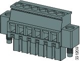
The alarm connector provides six alarm wire connections. The connector is attached to the switch front panel with the provided captive screws.
Both alarm input circuits can sense if the alarm input is open or closed. The alarm inputs can be activated for environmental, power supply, and port status alarm conditions. From the CLI, you can configure each alarm input as an open or closed contact.
The alarm output circuit is a relay with a normally open and a normally closed contact. The switch is configured to detect faults that are used to energize the relay coil and change the state on both of the relay contacts: normally open contacts close, and normally closed contacts open. The alarm output relay can be used to control an external alarm device, such as a bell or a light.
See the Cisco Connected Grid Switches System Management Software Configuration Guide for instructions on configuring the alarm relays.
For more information about the alarm connector, see Cable and Connectors
Management Ports
You can connect the switch to a PC running Microsoft Windows or to a terminal server through either the RJ-45 console port or the USB mini-Type B console port, also referred to as the USB-mini console port. These ports use the following connectors:
■![]() RJ-45 console port uses an RJ-45-to-DB-9 female cable.
RJ-45 console port uses an RJ-45-to-DB-9 female cable.
■![]() USB-mini console port (5-pin connector) uses a USB Type A-to-5-pin mini-Type B cable.
USB-mini console port (5-pin connector) uses a USB Type A-to-5-pin mini-Type B cable.
The USB-mini console interface speeds are the same as the RJ-45 console interface speeds.
To use the USB-mini console port, you must install the Cisco Windows USB device driver on the device that is connected to the USB-mini console port and that is running Microsoft Windows.
Note: For information about downloading the Cisco USB device driver, see the Installing the Cisco Microsoft Windows USB Device Driver.
With the Cisco Windows USB device driver, connecting and disconnecting the USB cable from the console port does not affect Windows HyperTerminal operations. Mac OS X or Linux requires no special drivers.
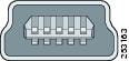
Note: The 5-pin mini-Type B connectors resemble the 4-pin mini-Type B connectors, but they are not compatible. Use only the 5-pin mini-Type B. See Figure 9.
The configurable inactivity timeout reactivates the RJ-45 console port if the USB-mini console port is activated, but no input activity occurs for a specified time period. When the USB-mini console port deactivates due to a timeout, you can restore its operation by disconnecting and reconnecting the USB cable. For information on using the CLI to configure the USB-mini console interface, see the Cisco Connected Grid Switches Interfaces Software Configuration Guide.
LEDs
You can use the LEDs to monitor the switch status, activity, and performance. Figure 10 and Figure 11 show the front panel LEDs.
Figure 10 LEDs on the IE 2000U Switch
|
|
|
||
|
|
|
||
|
|
|
||
|
|
|
||
|
|
|
System LED
The System LED shows whether the system is receiving power and is functioning properly.
Table 3 lists the system LED colors and their meanings.
|
|
|
|---|---|
USB-Mini Console LED
The USB-mini console LED shows which console port is in use. See Figure 10 for the LED location.
If you connect a cable to a console port, the switch automatically uses that port for console communication. If you connect two console cables, the USB-mini console port has priority. Table 4 describes the system LED colors and their meanings.
|
|
|
|---|---|
Alarm LEDs
Table 5 and Table 6 list the alarm LED colors and their meanings.
|
|
|
|---|---|
|
|
|
|---|---|
Power Status LEDs
The switch can operate with one or two DC power sources. Each DC input has an associated LED that shows the status of the corresponding DC input. If power is present on the circuit, the LED is green. If power is not present, the LED color depends on the alarm configuration. If alarms are configured, the LED is red when power is not present; otherwise, the LED is off.
If the switch has dual power sources, the switch draws power from the power source with the higher voltage. If one of the DC sources fails, the alternate DC source powers the switch, and the corresponding power status LED is green. The power status for the failed DC source is either off or red, depending on the alarm configuration.
Table 7 lists the power status LED colors and meanings.
Note: The Power A and Power B LEDs show that power is not present on the switch if the power input drops below the low valid level. The power status LEDs only show that power is present if the voltage at the switch input exceeds the valid level.
For information about the power LED colors during the boot fast sequence, see the Verifying Switch Operation.
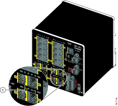
Port Status LEDs
Each 10/100BASE-T port, 10/100/1000BASE-T port, dual-purpose port, and SFP module slot has a port status LED, also called a port LED, as shown in Figure 10 and Figure 11. Table 8 displays LED information about the switch and the individual ports.
Dual-Purpose Port LEDs
Figure 11 shows the LEDs on a dual-purpose port. You can configure each port as either a 10/100/1000BASE-T port through the RJ-45 connector or as an SFP module, but not both at the same time.
There is one LED for each port and each media type (Ethernet or SFP module). Each port LED acts independently for the particular port and media. The LED colors have the same meanings as described in Table 8.
Figure 11 Dual-Purpose Port LEDs
|
|
PoE Status LED
The PoE STATUS LED is located on the front panel of the IE 2000U switch models that are equipped with PoE ports (IE 2000U-TC-GP).The LED displays the functionality and status of the PoE ports. The LED colors and meanings are listed in Table 9
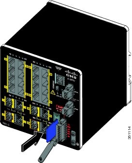
Flash Memory Card
The switch supports a flash memory card that makes it possible to replace a failed switch without reconfiguring the new switch. The slot for the flash memory card is on the front of the switch. See Figure 12.
The flash card is hot swappable and can be accessed on the front panel. A cover protects the flash card and holds the card firmly in place. The cover is hinged and closed with a captive screw. This prevents the card from coming loose and protects against shock and vibration.
Note: For more information on inserting and removing the flash memory card, see the Installing or Removing the Flash Memory Card.
Figure 12 Flash Memory Card Slot
Note: You can obtain replacement flash memory cards (SD-IE-1GB=) by calling Cisco Technical Assistance Center (TAC).
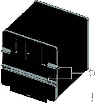
Rear Panel
The rear panel of the switch has a latch for installation on a DIN rail. See Figure 13. The latch is spring-loaded to move down to position the switch over a DIN rail and return to the original position to secure the switch to a DIN rail.
Figure 13 IE 2000U Switch Rear Panel
|
|
Management Options
The switch supports these management options:
■![]() Cisco Configuration Professional
Cisco Configuration Professional
Cisco Configuration Professional is a PC-based application that provides device management for switches and routers. It simplifies configuration of features through easy-to-use wizards.
The switch CLI is based on Cisco IOS software and is enhanced to support desktop-switching features. You can fully configure and monitor the switch. You can access the CLI either by connecting your management station directly to the switch management port or a console port, or by using Telnet from a remote management station. See the Cisco IOS Basics and File Management for Connected Grid Switches on Cisco.com for more information.
You can manage switches from an SNMP-compatible management station that is running platforms such as HP OpenView or SunNet Manager. The switch supports a comprehensive set of Management Information Base (MIB) extensions and four Remote Monitoring (RMON) groups. See the Cisco Connected Grid Switches System Management Software Configuration Guide on Cisco.com and the documentation that came with your SNMP application for more information.
Network Configurations
See the guides on Cisco.com for network configuration concepts and examples of using the switch to create dedicated network segments and interconnecting the segments through Gigabit Ethernet connections. For more information, go to:
www.cisco.com/go/ie2000u-docs
 Feedback