Zscaler Internet Access (ZIA) and Cisco Catalyst SD-WAN
Available Languages
Bias-Free Language
The documentation set for this product strives to use bias-free language. For the purposes of this documentation set, bias-free is defined as language that does not imply discrimination based on age, disability, gender, racial identity, ethnic identity, sexual orientation, socioeconomic status, and intersectionality. Exceptions may be present in the documentation due to language that is hardcoded in the user interfaces of the product software, language used based on RFP documentation, or language that is used by a referenced third-party product. Learn more about how Cisco is using Inclusive Language.
- US/Canada 800-553-2447
- Worldwide Support Phone Numbers
- All Tools
 Feedback
 Feedback
About the Guide
This document provides technical and configuration guidance for integrating Zscaler Internet Access (ZIA) and Cisco Catalyst SD-WAN successfully using the capabilities provided by Cisco Catalyst SD-WAN Manager version 20.9, vEdge version 20.6 and 20.9, and IOS XE SD-WAN WAN Edge version 17.9. It includes examples to show how to provision a new service to integrate ZIA and Cisco Catalyst SD-WAN IPsec or GRE tunnels using the SIG feature template implementation introduced in code versions 20.4/17.4. For Cisco Catalyst SD-WAN, configurations that use feature templates through SD-WAN Manager/ and command line interface (CLI) are both shown.
| Tech Tip |
| Cisco SD-WAN has been rebranded to Cisco Catalyst SD-WAN. As part of this rebranding, the vManage name has been changed to SD-WAN Manager, the vSmart name has been changed to SD-WAN Controller, and the vBond name has been changed to SD-WAN Validator. Together, the vManage, vSmart, and vBond will be referred to as the SD-WAN control components or the SD-WAN control complex in this document. |
The following Cisco Catalyst SD-WAN and ZIA use cases are chosen to be covered within this document:
● Single and Dual WAN Edge Design
● Active/standby and active/active tunnel deployment
● Automatic provisioning of IPsec and GRE tunnels
● Use of service route or centralized policy for traffic redirection
This document is a continuation of the previous Zscaler Internet Access (ZIA) and Cisco SD-WAN Deployment Guide which covered Zscaler and Cisco Catalyst SD-WAN traditional active/standby tunnels (pre 20.4 SD-WAN Manager/17.4 IOS XE SD-WAN code versions). See Appendix A for documentation revision information and Appendix F for additional Cisco Catalyst SD-WAN resource links.
The Zscaler portion of this document was authored by Zscaler and the Cisco Catalyst SD-WAN portion of this document was authored by Cisco. Both companies partnered to review and validate the information in this guide.
This document contains four major sections:
● The Define section gives background on the Zscaler and Cisco Catalyst SD-WAN solution.
● The Design section discusses the solution components, design aspects, and any prerequisites.
● The Deploy section provides information about various configurations and best practices.
● The Operate section shows how to manage different aspects of the solution.
Audience
This document is designed for Network Engineers and Network Architects interested in configuring and integrating ZIA access from Cisco WAN Edge routers. It assumes the reader has a basic comprehension of IP networking and is familiar with Cisco Catalyst SD-WAN concepts and configurations. For additional product and company resources, please refer to the Appendix section.
Hardware Used
To create this document, a sampling of different Cisco WAN Edge router platforms was tested in various use cases. They include a C8300-1N1S-6T, ISR4331, ISR1100-4G (Viptela OS), and vEdge 100b.
| Tech tip |
| End-of-Life milestones have been announced for the vEdge router and other select SD-WAN platforms (vEdge 100, vEdge 1000, vEdge 2000, vEdge 5000, select ISR4K, select ASR1K products, and select ISR1K products). See the following announcements for more information: https://www.cisco.com/c/en/us/products/routers/vedge-router/eos-eol-notice-listing.html |
Software Revisions
This document was written using Zscaler Internet Access version 6.2 and the following Cisco Catalyst SD-WAN versions:
● 20.9.3.1 SD-WAN Manager code version
● 20.6.5.3 (vEdge 100b) and 20.9.3 (ISR1100-4G) vEdge code versions (vEdge platforms have been announced End-of-Sales and not all are supported by 20.9.x code)
● 17.9.3 IOS XE SD-WAN code version
Document Prerequisites
Zscaler Internet Access (ZIA)
This document requires a working instance of ZIA 6.2 (or newer) and administrator login credentials to ZIA.
Cisco Catalyst SD-WAN
This document assumes you have the Cisco Catalyst SD-WAN control components (SD-WAN Manager, SD-WAN Validator, and SD-WAN Controller) already built and operational, either through the Cisco cloud service or on-premise. It is recommended that you use SD-WAN Manager to configure and manage the WAN Edge routers.
It is also assumed that the WAN Edge devices are already connected to the control components in the SD-WAN overlay, and a basic device template configuration from SD-WAN Manager has been deployed on them. See Appendix G for base device and feature template configurations and Appendix H for a summary of feature templates required to configure the Zscaler tunnel use cases. Appendix I and J reflect CLI-equivalent configurations for IOS XE SD-WAN and vEdge, respectively.
This document requires administrator login credentials to SD-WAN Manager and SSH administrator login credentials to the WAN Edge routers.
Cisco Catalyst SD-WAN Design Overview
Enterprises can take advantage of secure local Internet breakout by using Cisco Catalyst SD-WAN combined with Zscaler. Using Cisco Catalyst SD-WAN, the network administrator can decide what traffic should be forwarded to Zscaler, using either GRE or IPsec tunnels.
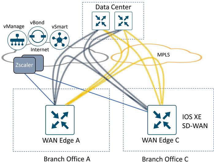
The following example topology shows a Cisco Catalyst SD-WAN network with two transports (MPLS and Internet) and the SD-WAN control components reachable through the Internet cloud. Two branch sites are shown with a data center site. SD-WAN fabric (IPsec) tunnels are built between each WAN Edge router at each site for corporate traffic. A separate pair of GRE or IPsec tunnels are built from each branch router to Zscaler Enforcement Nodes (ZEN) for access to Internet and SaaS applications. If the local Internet transport fails, traffic can traverse the SD-WAN overlay over the MPLS transport to the data center and access the Internet from there.
Feature Background/History
| Tech tip |
| Testing was done on 20.9 SD-WAN Manager, 20.9/20.6 vEdge versions, and 17.9 IOS XE SD-WAN versions. See Cisco Recommended SD-WAN Software Versions for Controllers and WAN Edge Routers for information on the latest recommended release. |
Support through Cisco Catalyst SD-WAN 20.3/17.3 code versions (Traditional Active/Standby Tunnels and L7 Health Checking)
Early support for Zscaler tunnels included GRE or IPsec tunnels that could be configured manually through Interface VPN templates in SD-WAN Manager, either in the transport VPN (IPsec or GRE) or service VPN (IPsec). A single active/standby tunnel pair is supported per WAN Edge router, along with L7 health check probes running between the WAN Edge router and the respective Zscaler Enforcement node (ZEN). The active tunnel is typically connected to a primary ZEN while the standby tunnel is connected to a secondary ZEN. See the Zscaler Internet Access (ZIA) and Cisco SD-WAN Deployment Guide for more information.
Note: The recommended way to configure SIG tunnels is through the SIG feature template, supported in Cisco SD-WAN 20.4/17.4 and later code versions.
Cisco Catalyst SD-WAN 20.4/17.4 code versions (Active/Active Manual ECMP Tunnels and Traffic Steering through SIG Route and Centralized Data Policy using SIG Templates)
The following SIG enhancements were introduced in 20.4/17.4:
● A new SD-WAN Manager Secure Internet Gateway (SIG) feature template is introduced where you can configure up to 4 active/backup tunnels pairs to get the benefit of equal cost multipath (ECMP) load balancing and allow more traffic bandwidth to be redirected to Zscaler. Zscaler tunnels are configured manually using the SIG feature template and choosing the third-party SIG Provider option. Only one SIG template can be attached per device, and it can only be GRE or IPsec, and not a mix of both per device.
● Weights can be assigned to the tunnels so that more traffic can traverse one tunnel over another if need be.
● Traffic redirection into the tunnels is accomplished through a new SIG service route, which reduces the administrative overhead of configuring static routes that require site-specific next-hop IP addresses. The SIG service route tracks the state of the SIG tunnels, and if all are marked down, the SIG service route is removed from the routing table.
● Traffic redirection to Zscaler can also be configured through centralized data policy, giving additional flexibility and granularity to choose specific application traffic.
| Tech tip |
| Moving forward, all new features (including SIG route and SIG data policy) leverage the SIG feature template. The SIG feature template allows you to configure automatic Zscaler and Umbrella tunnels, and manual third-party tunnels. Tunnel types include IPsec and GRE. |
Cisco Catalyst SD-WAN 20.5/17.5 code versions (Zscaler Automatic IPsec Tunnel Provisioning)
In 20.5/17.5, there were several updates to the SIG feature template, including accommodations for automatic discovery and tunnel provisioning to the closest Zscaler data centers based on geolocation. Layer 7 Health checking is automated and supported for vEdge WAN Edge routers as well. Only one automatic active/standby Zscaler tunnel pair is supported in this version.
Cisco Catalyst SD-WAN 20.6/17.6 code versions (L7 Health Checks for IPsec Auto Tunnels for IOS XE SD-WAN routers and Cloud onRamp for SaaS over SIG Tunnel Support)
In 20.6/17.6, up to four pairs of active/standby IPsec tunnels are supported with automatic provisioning. L7 automated health checking is introduced as an in-product BETA feature for Zscaler IPsec Auto Tunnels for IOS XE SD-WAN routers. Official support for IOS XE SD-WAN L7 Health checking for automatic IPsec Zscaler tunnels is in version 20.6.2/17.6.2. Loopback interfaces can be used as source interfaces for SIG tunnels for IOS XE SD-WAN routers only. Cloud onramp for SaaS over SIG tunnels is also a newly supported feature in this version.
Cisco Catalyst SD-WAN 20.7/17.7 code versions (VRRP Interface Tracker support for SIG Tunnels)
In 20.7/17.7, VRRP tracking for SIG and Tunnel interfaces is supported for IOS-XE SD-WAN routers. If a tunnel which is being tracked goes down, the VRRP primary Edge router decrements its priority and the backup VRRP router transitions to the primary role. For vEdge, this feature was introduced in 20.4 in CLI, but SD-WAN Manager feature template support is introduced in 20.7.
Cisco Catalyst SD-WAN 20.8/17.8 code versions (Multiple SIG Enhancements)
The following SIG enhancements were introduced in 20.8/17.8:
● Centralized data policy fallback support: In the event of a SIG tunnel failure, the SD-WAN overlay routes can be taken to avoid traffic blackholing (IOS XE SD-WAN only).
● ECMP based on source IP address: This allows traffic with the same source IP address to be directed to the same SIG tunnel instead of being potentially hashed to multiple SIG tunnels (IOS XE SD-WAN only).
● IPsec tunnel creation improvements for active/active SIG tunnels: This feature ensures that IPsec control and data connections are pinned and exit out the same physical interface. DNS traffic for L7 health checks can still potentially be routed out the incorrect interface when using loopback interfaces as the source interface for GRE or IPsec tunnels, so a configuration workaround is required in this and previous releases (IOS XE SD-WAN only).
● Layer 7 health check for generic (manual) SIG tunnels using the SIG feature template.
Cisco Catalyst SD-WAN 20.9/17.9 code versions (Zscaler Automatic GRE Tunnel Provisioning and SIG Tunnel Monitoring)
In 20.9/17.9, the following SIG enhancements were introduced:
· Automatic provisioning of GRE-based SIG tunnels, which includes support for L7 heath checks, SIG data policy fallback, multiple active/active tunnels with weighted load-balancing option, and ECMP traffic load balancing based on Source IP address (IOS XE SD-WAN only).
· SIG tunnel monitoring, which provides enhanced monitoring and visibility for automatic SIG tunnels which includes state of the SIG tunnel, and various security event notifications (IOS XE SD-WAN and automatic SIG tunnels only).
· Global sig credentials template enhancement: With this enhancement, there is no longer a way to create a separate SIG credentials feature template and a requirement to manually add the SIG credentials template to the device template under the Additional Templates section. Now, a credentials template is filled out only one time when a SIG feature template is first created with a specific SIG provider. The credentials template is added automatically to a device template when the SIG feature template is added.
The SIG features and hardware/software support can be summarized in the following tables:
| Feature |
IOS XE SD-WAN Min Code Version |
vEdge Min Code Version |
L7 Health Check Support (IOS XE SD-WAN/vEdge) |
| IPsec or GRE Manual (3rd party/generic) tunnels using SIG Feature Templates (Up to 4 active/standby tunnel pairs with 4-tuple ECMP/weighted load balancing) |
17.4 |
20.4 |
17.8/ 20.8* |
| IPsec Zscaler Auto Tunnels (One active/standby tunnel pair) |
17.5 |
20.5 |
N/A/ 20.5 |
| IPsec Zscaler Auto Tunnels (Up to 4 active/standby tunnel pairs with 4-tuple ECMP/weighted load balancing) |
17.6 |
20.6 |
17.6.2/20.6 |
| GRE Zscaler Auto Tunnels (Up to 4 active/standby tunnel pairs with 4-tuple ECMP/weighted load balancing) |
17.9** |
N/A |
17.9/ N/A |
*If you need earlier GRE support requiring L7 health checks, use traditional active/standby tunnels utilizing Interface VPN templates. Use Auto Tunnels and SIG feature templates whenever possible.
**Caveat: GRE auto tunnel loopback as a source interface tunnel is not supported until 17.9.2.
| Feature |
IOS XE SD-WAN Min Code Version |
vEdge Min Code Version |
Fallback Routing Support (IOS XE SD-WAN/vEdge) |
| SIG Route |
17.4 |
20.4 |
17.4/ 20.4 |
| SIG Data Policy |
17.4 |
20.4 |
17.8/ N/A* |
*Without Fallback Routing support for SIG data policy, SIG traffic can blackhole if the SIG tunnels are down. In earlier code versions, rely on the SIG route for SIG traffic if possible, so SIG traffic falls back to routing when the SIG tunnels are down.
| Feature |
IOS XE SD-WAN Min Code Version |
vEdge Min Code Version |
| Cloud onRamp for SaaS via SIG Tunnel |
17.6 |
20.6 |
| VRRP Interface Tracker Support for SIG Tunnels |
17.7 |
20.7 (20.4 in CLI) |
| SIG ECMP based on Source IP address |
17.8 (CLI add-on template) |
N/A |
| SIG Tunnel Monitoring |
17.9 |
N/A |
| Global SIG Credentials Template Enhancement |
17.9 |
20.9 |
There are several points to consider when designing for Cisco Catalyst SD-WAN and Zscaler integration. It is also important to understand what features are supported in any code version, as this can affect the SIG configuration and design.
● What tunnel protocol do you use? IPsec or GRE? Are there any design restrictions related to the tunnel protocol type?
● What tunnel liveliness methods are available? Do tunnels support L7 health checking?
● What is the Equal-Cost Multi-Path (ECMP) routing behavior for multiple, active tunnels?
● Where are your primary vs secondary Zscaler data centers located?
● What are the high availability and load balancing options?
● What method do you use to redirect traffic from service-side VPN to the SIG tunnel? Is a fallback method supported?
● Are you using single Edge or dual Edges?
● Are you using automatic or manual tunnels?
The following topics address these considerations:
GRE and IPsec Tunnels
Zscaler supports both Generic Routing Encapsulation (GRE) and Internet Protocol Security (IPsec) tunnels from Edge devices to transport Internet traffic needing to first traverse the Zscaler Internet Access (ZIA) node.
| Tech tip |
| An active IPsec tunnel is defined by a unique 4-tuple of source IP address/interface, source port, destination IP address, and destination port pair. Multiple IPsec tunnels can exist that reference the same source or destination IP address, but each tunnel must have a unique 4-tuple for the tunnel to be up and operational. IPsec tunnels are dynamically added on the Zscaler side, so their source IP addresses and source ports can change. GRE tunnels do not have source or destination ports and are statically mapped using source IP address via API or manual configuration on the Zscaler side, meaning that multiple GRE tunnels cannot be sourced from the same IP address. Also, since they are mapped manually, their source IP addresses cannot change once mapped. |
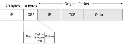
Packet Format and NAT
GRE is neither TCP nor UDP but has its own protocol number (47). Because GRE is a protocol without source or destination ports, GRE packets are unable to be translated by Port Address Translation (PAT) devices. The source IP address of a GRE packet can, however, be translated with Network Address Translation (NAT) with no overload, which includes static or dynamic NAT, where a single IP address is mapped only to a single publicly routable IP address. This is because no ports need to be mapped.
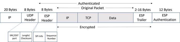
In an IPsec packet, ESP is also a protocol without ports which prevents it from being translated by PAT devices. IPsec, however, can use NAT traversal (NAT-T) to have ESP packets traverse NAT. If both ends of the IPsec connection support NAT-T, then Nat-Discovery packets are exchanged during the ISAKMP exchange. If NAT is detected, then ISAKMP packets change from UDP port 500 to UDP port 4500. ESP data packets are also encapsulated inside a UDP packet with source and destination ports equal to 4500, so the packet becomes capable of being translated by a PAT device.
Throughput
Zscaler GRE tunnels can support higher throughput than IPsec tunnels in the Zscaler cloud. At the time of this writing, IPsec tunnels can support 400 Mbps each while GRE tunnels can support 1 Gbps each, but it can vary depending on the Zscaler cloud and ZEN node you are connecting to.
Tunnel Source IP Addressing
Zscaler GRE tunnels require a source IP address on the WAN Edge router that is a separate, unique IP public address per destination that is constant or static. This source IP address is registered on the ZIA through APIs and is used as authentication for the GRE tunnel. Zscaler IPsec tunnels can be static or dynamic addressing and is not required to have a separate, unique IP public address (as long as the source port varies per tunnel destination). IKEv2 is used for IPsec tunnel authentication to ZIA.
| Tech tip |
| GRE tunnels are not influenced by NAT defined on the interface of a WAN Edge router; their source IP address remains unchanged as it transits the WAN Edge router. GRE tunnels must be either directly sourced by a public IP address or be subjected to a one-to-one NAT translation by an external device. Source IP address for IPsec tunnels, on the other hand, are subjected to NAT defined on the interface of a WAN Edge router as traffic transits. |
Tunnel Liveliness
GRE Keepalives and DPD
GRE Keepalives for GRE tunnels and Dead Peer Detection (DPD) for IPsec tunnels are traditional methods for a local router to determine whether the remote router at the end of a tunnel is reachable and able to forward traffic. Zscaler best practices advise that GRE Keepalives and DPD packets are sent no more than one every 10 seconds.
| Tech tip |
| If the router sits behind any NAT device, GRE keepalives are not passed. If behind a NAT device, it is recommended that you disable GRE keepalives by setting the interval and retries to 0. Keep in mind that GRE data packets are unable to be translated by PAT devices but can be translated through a NAT device where only one single IP address is mapped to a single publicly routable IP address because no port mapping is required. IOS XE SD-WAN routers do not support GRE keepalives through feature templates, only vEdge routers do. For IOS XE SD-WAN routers, GRE keepalives can be configured through CLI or CLI add-on feature templates. vEdge routers currently support only periodic DPD. On-demand DPD is currently the default for IOS XE SD-WAN routers. |
Layer 7 Health Checks
GRE Keepalives and Dead Peer Detection can validate whether the network path is up between the tunnel source and destination, but the mechanisms cannot verify whether a particular service or application is up and operational beyond the tunnel and ZEN node.
Layer 7 health checking allows you to monitor latency and reachability based on HTTP request and response probes to a URL that is reachable through the Zscaler tunnels and allows you to fail over to an alternate tunnel when reachability fails or latency degrades beyond an acceptable threshold.
To check the health of the application stack of the Zscaler node, Zscaler recommends not performing L7 health checks to commonly visited websites but instead recommends using the following URL for the tracker, which is not publicly accessible, but only reachable through a Zscaler tunnel:
http://gateway.<zscaler_cloud>.net/vpntest
L7 health checks should not be sent more than one every 5 seconds.
Equal-Cost Multi-Path (ECMP) Routing
Four-Tuple ECMP
In the presence of multiple, equal-cost active paths, traffic is normally routed to an interface based on the hashing of the IP flow Four-tuple (source IP address + destination IP address + source port + destination port). Because it is based on a hash, the traffic distribution may not be exactly equal across the tunnels but with enough variability in IP addressing and ports in the network traffic, traffic distribution gets more evenly distributed across the ECMP interfaces.
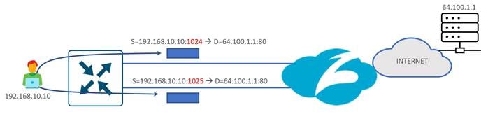
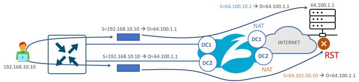
There are several applications that are known to fork off multiple sessions for a single user session (O365, Google Services, Facebook, etc.). If you have two active SIG tunnels that are pinned to two different Zscaler data centers, ECMP could pin flows from a single user to separate tunnels. The cloud application could see different client IP addresses for the same session, since NAT is applied to their source IP addresses from two different data centers, and thus, session resets from the server could occur.
| Tech tip |
| Be careful when designing using multiple active/active or active/standby links with 4-tuple hashed ECMP (default setting). Especially in the case of routed dual-Edge sites, you want to be careful that hashed sessions for the same user do not get distributed over multiple links going to different Zscaler data centers. You must also consider how traffic is hashed during failure scenarios as well. There also may be cases where there are active/active tunnels going to the same Zscaler data center and users could be experiencing application performance issues due to a single user session taking multiple, equal-cost paths if tunnels are experiencing varying levels of latency or loss. In these cases, you could ensure that users are not being hashed to different Edge devices or different transports. |
Source IP-Based ECMP
Starting in 20.8/17.8, ECMP can be configured to hash according to source IP rather than a 4-tuple. This would allow traffic with the same source IP address to be directed to the same SIG tunnel instead of being potentially hashed to multiple SIG tunnels. Note that this is supported only by IOS XE SD-WAN routers. It is enabled with the command, ip cef load-sharing algorithm src-only, through an add-on CLI template. This would give you more design flexibility in configuring your tunnel destinations and setting up active/standby pairs.
| Tech tip |
| In Edge versions prior to 17.12, source IP-based ECMP can be configured only when the WAN Edge router is in CLI mode. If you try to use an add-on CLI template, the ECMP configuration goes back to the default, which is four-tuple. This affects hardware-based IOS XE SD-WAN routers and is fixed in 17.12. |
Primary vs Secondary Data Center Placement
The primary Zscaler data center is typically chosen to be the closest data center to your remote site and should be used for your active tunnels. The secondary data center is typically chosen as the next closest data center to your remote site and should be used for your standby tunnels.
It is not recommended to design active/active tunnels going to multiple datacenters, even if you make use out of source IP-based ECMP. Latency/performance could vary from user to user depending on which tunnels are taken to Zscaler.
Zscaler Active/Standby Tunnel Combinations
The following shows examples of different active/standby tunnel combinations to ZIA over dual Internet and hybrid deployments (MPLS and Internet). The deployed tunnels are of one type, either GRE or IPsec, and not a combination of both. Up to four active/standby pairs are supported. Route or policy directs traffic out the active tunnels to Zscaler. Standby tunnels are fully up and operational, but traffic is not forwarded over them to Zscaler until their corresponding active tunnel pair partner is marked down or exceeds the latency threshold of the L7 health checks.
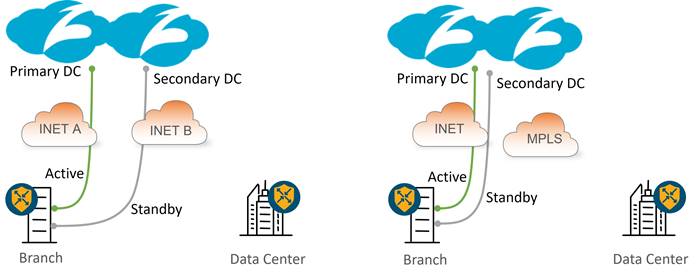
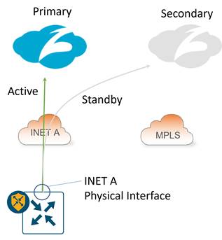
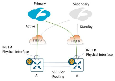
One Active/Standby Tunnel Pair
The following diagram shows an example of one active and one standby tunnel deployment at sites with single and dual Internet circuits. In hybrid deployments, an MPLS path may offer a backhauled path to the Internet via an Internet gateway at a data center or regional hub site. In either deployment, if the Zscaler node or active tunnel becomes unreachable or exceeds the latency threshold (with L7 health checks enabled), then the standby tunnel is activated. In the hybrid deployment, if the INET transport goes down or if both tunnels over the INET transport exceed the latency thresholds (with L7 health checks enabled), then traffic can still take the default route over the SD-WAN overlay over the MPLS transport to the data center, where traffic can access the Internet, either through an on-premise security stack or via a separate SIG tunnel originating from the data center hub router.
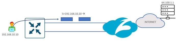
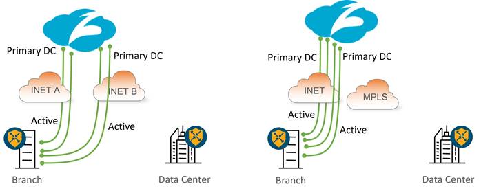
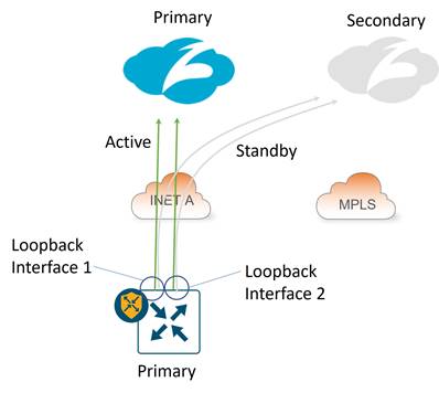
Multiple Active/Active Tunnels with Equal-Cost Multipath (ECMP)
More traffic is shifting to the cloud, and because tunnels to Zscaler are limited in bandwidth, it becomes necessary to support multiple active tunnels. The following diagram shows an example of an active/active tunnel deployment at sites with single and dual Internet circuits. In either deployment, if an active tunnel becomes unreachable or exceeds the latency threshold (with L7 health checks enabled), then traffic is rehashed to one of the remaining tunnels. In the hybrid deployment, if the INET transport goes down or if all tunnels over the INET transport exceed the latency thresholds (with L7 health checks enabled), then traffic can still take the default route over the SD-WAN overlay over the MPLS transport to the data center, where traffic can access the Internet, either through an on-premise security stack or via a separate SIG tunnel originating from the data center hub router. In either deployment, if the Zscaler node becomes unreachable, traffic can fall back to the data center over the SD-WAN overlay.
Note that all active tunnels are terminated on the same Zscaler data center.
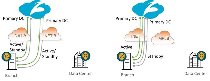
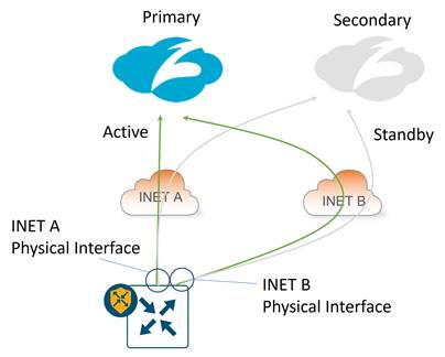
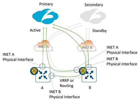
Multiple Active/Standby Tunnel Pairs
The following diagram shows an example of a multiple active/standby tunnel pair deployment at sites with dual Internet and hybrid circuits. In either deployment, if an active tunnel becomes unreachable or exceeds the latency threshold (with L7 health checks enabled), then its corresponding standby tunnel is activated. In the hybrid deployment, if the INET transport goes down or if all tunnels over the INET transport exceed the latency thresholds (with L7 health checks enabled), then traffic can still take the default route over the SD-WAN overlay over the MPLS transport to the data center, where traffic can access the Internet, either through an on-premise security stack or via a separate SIG tunnel originating from the data center hub router. In either deployment, if the Zscaler node becomes unreachable, traffic can fall back to the data center over the SD-WAN overlay.
| Tech tip |
| In this scenario, 4-tuple ECMP is being used which is why the standby tunnels are going to the same DC as the active tunnels. You do not want a single user session to go to two different DCs if one of the standby links were to go active. Starting in 20.8/17.8 code, source IP-based ECMP can be configured, where a secondary DC for the standby tunnels can be used instead. |
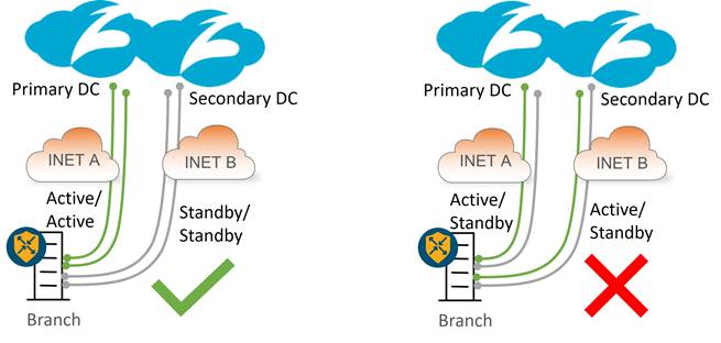
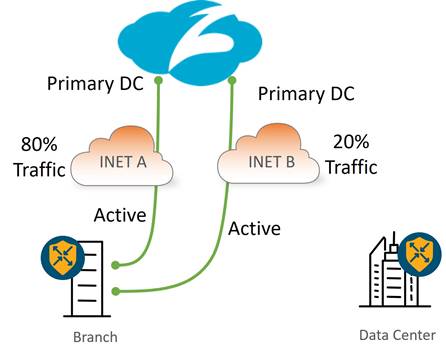
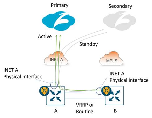
Active/Active Tunnels with Weighted Load Balancing
The following diagram shows an example of an active/active tunnel deployment spread across two Internet transports. Available bandwidth may differ between the transports so weights can be assigned to each tunnel so different traffic bandwidth amounts traverse each transport. In this example, weights are configured for each tunnel so that 80% of the traffic traverses INET A while 20% of the traffic traverses INET B. if an active tunnel becomes unreachable or exceeds the latency threshold (with L7 health checks enabled), then traffic is rehashed to one of the remaining tunnels.
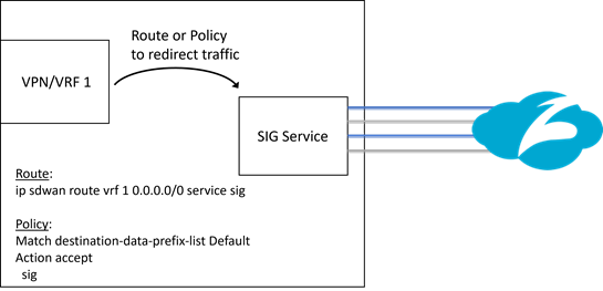
User Traffic Redirection
Once the GRE or IPsec tunnels are configured and activated, there are two ways to direct user traffic to the tunnel:
● With a static route to rely on destination-based routing, which is typically a default route where all Internet-bound traffic is sent. 20.4/17.4 code version introduces a new type of route for Zscaler or other third-party tunnels called a Service Route which has a next hop that points to the SIG Service.
● With a centralized data policy which allows you to customize the traffic sent to the Zscaler service. 20.4/17.4 now supports centralized policy for both vEdge and IOS XE SD-WAN devices where you can rely on prefix-lists and applications lists to direct desired traffic to the SIG Service.
| Tech tip |
| If both service routes and centralized policy are configured to direct user traffic, centralized policy takes precedence. It may be desirable to configure both a SIG service route and policy because in dual-Edge branches with layer 3 routing, the SIG service route can be redistributed into a routing protocol at the local site, and if the SIG tunnels become unreachable on an Edge router, the route is withdrawn so traffic can be directed to the opposite Edge with active SIG tunnels. Once traffic reaches the Edge router with active SIG tunnels, policy (or routing) can be used to direct traffic to the SIG tunnel. Fallback routing was not introduced for centralized policy until 20.8/17.8 for Cisco IOS XE SD-WAN only. Without fallback routing, traffic can blackhole when the SIG tunnel becomes unavailable. Use a SIG service route for SIG traffic instead as a workaround. |
WAN Edge with Zscaler Site Tunnel Design
This section covers the various aspects of single WAN Edge and dual WAN Edge site designs with Zscaler integration. Each WAN Edge router supports up to 4 active/standby tunnel pairs. For multiple active/standby tunnel pairs, you should consider using IP source-based ECMP for load-balancing traffic.
| Tech tip |
| Note that the source IP address of an IPsec tunnel is subjected to NAT/PAT defined on the WAN Edge interface, while the source IP address of a GRE tunnel is not. The source IP address of a GRE tunnel will pass unchanged. Note that NAT still needs to be defined on each physical interface where Zscaler tunnels will be sourced for both GRE and IPsec tunnels so API calls can succeed. In addition, if an external device is used to NAT the source IP address of a tunnel, IPsec tunnels can use dynamic NAT/PAT, while GRE tunnels each must use unique, 1-to-1 NAT addressing. |
Single WAN-Edge Design
This section shows a few examples of single WAN-Edge designs with Zscaler integration.
Hybrid transport with 1 active/standby tunnel:
IPsec: The tunnel source for both the active and standby tunnels is the INET A physical interface, which can be a publicly routable or a private IP address. If it is a private address, NAT/PAT is required by an external device to translate the tunnel source IP address into a publicly routable IP address.
GRE: The tunnel source for both the active and standby tunnels is the INET A physical interface, which can be a publicly routable or a private IP address. If it is a private address, 1-to-1 NAT is required by an external device to translate the tunnel source IP address into a publicly routable IP address.
Hybrid transport with multiple active/standby tunnels:
IPsec: The tunnel source is a loopback interface for each active/standby pair. The loopback interfaces can be privately addressed, then subjected to NAT/PAT on the INET A physical interface. If the INET A interface is privately addressed, NAT/PAT on an external device is needed to make the tunnel source IP addresses publicly routable.
GRE: The tunnel source is a loopback interface for each active/standby pair. The loopback interfaces can either be publicly addressed or if private addressing is used, each tunnel source IP address must be translated to a unique 1-to-1 publicly-routable address by an external device.
| Tech tip |
| With this design, a CLI add-on template for router local policy is required for successful L7 health checking for IOS XE SD-WAN routers. Also, there is no support for loopback interfaces as tunnel sources with the vEdge platform. |
Dual-Internet transport with 1 active/standby tunnel per transport:
IPsec: The tunnel source for the active/standby tunnel pair over INET A is the INET A physical interface, and for the active/standby tunnel pair over INET B is the INET B physical interface. The tunnel source IP address can be a publicly routable or a private IP address. If it is a private address, NAT/PAT is required by an external device to translate the tunnel source IP address into a publicly routable IP address.
GRE: The tunnel source for the active/standby tunnel pair over INET A is the INET A physical interface, and for the active/standby tunnel pair over INET B is the INET B physical interface. The tunnel source IP address can be a publicly routable or a private IP address. If it is a private address, one-to-one NAT is required by an external device to translate the tunnel source IP address into a unique, publicly routable IP address.
Dual WAN-Edge Design
This section shows a few examples of dual WAN-Edge designs with Zscaler integration. The dual routers use VRRP or routing on the service side.
Hybrid transport with 1 active/standby tunnel per WAN Edge:
IPsec: The tunnel source for the active/standby tunnel pair on both WAN Edge routers is the INET A physical interface, which for the B-side router, is on the TLOC extension link between the routers. The tunnel source IP address can be a publicly routable or a private IP address. The B-side router’s tunnel source IP address is subjected to NAT/PAT on router A’s INET A interface. If router A’s INET A interface is a private address, NAT/PAT is required by an external device to translate the tunnel source IP address into a publicly routable IP address.
GRE: The tunnel source for the active/standby tunnel pair on both WAN Edge routers is the INET A physical interface, which for the B-side router, is on the TLOC extension link between routers. The tunnel source IP address can be publicly routable or a private IP address. The B-side router’s tunnel source IP address is not subjected to NAT on router A’s INET A interface and will stay unchanged. If either tunnel source is a private address, a one-to-one NAT is required by an external device to translate each tunnel source IP address into a unique, publicly routable IP address.
Dual-Internet transport with 1 active/standby tunnel per WAN Edge:
IPsec: The tunnel source for the active/standby tunnel pair on WAN Edge A is the INET A physical interface, and for WAN Edge B, it is the INET B physical interface. The tunnel source IP address can be a publicly routable or a private IP address. If either INET A or INET B interface has a private address, NAT/PAT is required by an external device to translate the tunnel source IP address into a publicly routable IP address.
GRE: The tunnel source for the active/standby tunnel pair on WAN Edge A is the INET A physical interface, and for WAN Edge B, it is the INET B physical interface. The tunnel source IP address can be publicly routable or a private IP address. If either tunnel source is a private address, a one-to-one NAT is required by an external device to translate the tunnel source IP address into a unique, publicly routable IP address.
Dual-Internet transport with 2 active/standby tunnels per WAN Edge:
IPsec: The tunnel source for the active/standby tunnel pair on both WAN Edge routers is each INET physical interface. The tunnel source IP address can be a publicly routable or a private IP address. The B-side router’s INET A tunnel source IP address is subjected to NAT/PAT on router A’s INET A interface, and the A-side router’s INET B tunnel source IP address is subjected to NAT/PAT on router B’s INET B interface. If the INET interfaces connecting directly to the transports are privately addressed, NAT/PAT is required by an external device to translate each tunnel source IP address into a publicly routable IP address.
GRE: The tunnel source for the active/standby tunnel pair on both WAN Edge routers is each INET physical interface. The tunnel source IP address can be publicly routable or a private IP address. The B-side router’s INET A tunnel source IP address is not subjected to NAT on router A’s INET A interface, and the A-side router’s INET B tunnel source IP address is not subjected to NAT on router B’s INET B interface – each GRE tunnel bypasses NAT. If any tunnel source is a private address, a one-to-one NAT is required by an external device to translate each tunnel source IP address into a unique, publicly routable IP address.
Dual WAN Edge with Zscaler Site Service-side Design
For dual-router sites, redundancy on the service side VPNs can be achieved with VRRP (layer 2) or routing (layer 3). When you are doing fallback routing with a SIG route or SIG data policy, you need to be especially careful when you have a DIA NAT route present. If the SIG tunnel becomes inactive and traffic is subjected to fallback routing, traffic can take the DIA NAT default route (preferred over the default route from the overlay), and that might be undesirable.
Virtual Router Redundancy Protocol (VRRP)
With VRRP, one WAN Edge router is declared primary and the other one standby on a per-VPN basis. The primary router forwards Zscaler traffic to Zscaler tunnels directly connected to the WAN Edge router, either through a SIG route or through centralized data policy. Use a different VRRP primary per VPN to utilize the Zscaler tunnels of both Edge routers.
● VRRP interface tracker: Starting in 20.7/17.7, the SIG tunnel can be tracked and bound to the VRRP protocol. If the tunnel goes down, the VRRP primary decrements its priority and the backup router can take over the primary role.
● TLOC change preference: Starting in 20.7/17.7, the TLOC preference of the VRRP primary router gets increased by a configured value to avoid asymmetric traffic from other SD-WAN sites by ensuring traffic from across the overlay (WAN to LAN) is sent to the VRRP primary router. LAN to WAN traffic already uses the primary VRRP router as the default gateway.
Routing
With routing, be careful with equal-cost path route hashing, as a single user session could be split between SD-WAN routers, each with their own active tunnels, which could have performance implications. You can set up routing metrics so that there is a primary/secondary router per VRF. Even if you are using data policy for SIG traffic forwarding, you can utilize the SIG route to advertise a default into the service-side routing protocol. Be careful with redistributing the SIG default route, the NAT DIA default route, and the overlay default route (default route that comes from another site through the SD-WAN overlay) into the service-side routing protocol at the same time – the default metric behavior of each varies depending on the routing protocol. The following is a summary of the behavior in this code version:
Baseline
The following shows the admin distance and metric for each default route type installed in the service VPN of the WAN Edge router. The SIG route is preferred with an admin distance of 2.
| Default Route |
Route Type |
Admin Distance/Metric |
| SIG route (0.0.0.0/0)* |
S (Static) |
[2/65535] |
| NAT DIA route (0.0.0.0/0) |
Nd (NAT DIA) |
[6/0] |
| Overlay default route (0.0.0.0/0) |
m (OMP) |
[251/0] |
OSPF
In order to inject a default route into OSPF, you need to use the default-originate option in the OSPF protocol. By default, the route appears in the next-hop router as an E2 route with an admin distance of 110 and a metric of 1, regardless of which route is installed in the routing table on the WAN Edge router.
O*E2 0.0.0.0/0 [110/1] via 10.219.100.6, 00:00:22, GigabitEthernet2/0/1
BGP
To inject the different default routes into EBGP on the service side, you need to redistribute each protocol in the BGP feature template and include the default-originate configuration in BGP as well.
Use redistribute omp for the OMP default route, use redistribute nat for the DIA NAT route, and use redistribute static for the SIG route. By default, the following BGP routes with these default metrics are generated in this lab topology, with the NAT DIA route being preferred with a metric of 0:
| Default Route |
Route Type and Admin Distance/Metric |
| SIG route (0.0.0.0/0) |
B* 0.0.0.0/0 [20/65535] |
| NAT DIA route (0.0.0.0/0)* |
B* 0.0.0.0/0 [20/0] |
| Overlay default route (0.0.0.0/0) |
B* 0.0.0.0/0 [20/1000] |
To change the metrics to prefer the SIG route, define a router policy for each redistribution statement in the BGP feature template that needs a metric modified and add them to the localized policy attached to the WAN Edge router.
EIGRP
To inject the different default routes into EIGRP on the service side, you need to redistribute each protocol in the EIGRP feature template.
Use redistribute omp for the OMP default route, use redistribute nat-route for the DIA NAT route, and use redistribute static for the SIG route. By default, the following External EIGRP routes with these default metrics are generated in this lab topology, with both the NAT DIA route and the OMP route being preferred with a metric of 5120.
| Default Route |
Route Type and Admin Distance/Metric |
| SIG route (0.0.0.0/0) |
D*EX 0.0.0.0/0 [170/76805120] |
| NAT DIA route (0.0.0.0/0)* |
D*EX 0.0.0.0/0 [170/5120] |
| Overlay default route (0.0.0.0/0)* |
D*EX 0.0.0.0/0 [170/5120] |
To change the metrics to prefer the SIG route, use a CLI add-on template to define the EIGRP metric associated with each redistribute statement. For example, the following assigns the best metric to the SIG default route, the second-best metric to the NAT DIA default route, and the third best metric to the OMP default route metric.
router eigrp eigrp-name
!
address-family ipv4 unicast vrf 1 autonomous-system 100
!
topology base
redistribute static metric 1000000000 0 255 1 1500
redistribute nat-route dia metric 1000000 100 255 1 1500
redistribute omp metric 100000 1000 255 1 1500
SIG Service
Starting in 20.4/17.4, Zscaler tunnels can make use of the SIG Service construct that was introduced in SD-WAN Manager for integration with Cisco Umbrella Secure Internet Gateway (SIG). The SIG service keeps track of the state and next hop of the tunnels, in addition to redirecting traffic into the tunnels from the service VPN. Traffic redirection at the branch can be implemented locally through routing (defined in the service VPN feature templates) or as a centralized data policy action.
New SIG Workflow
Starting in 20.4/17.4, a new Unified Secure Interface Gateway (SIG) workflow is introduced with the Secure Internet Gateway (SIG) feature template, which greatly simplifies the SIG tunnel configuration process regardless of the tunnel type (Umbrella, Zscaler, other 3rd party IPsec or GRE tunnels). Only one SIG template is needed to configure multiple tunnels and is attached to the device template under the transport VPN. A configuration is introduced in IOS XE SD-WAN which allows multiple service VPNs to use the tunnel created with the SIG template (tunnel vrf multiplexing).
| Tech tip |
| Only one SIG template is allowed per device template. |
In SD-WAN Manager version 20.9, the Secure Internet Gateway (SIG) template is divided up into several sections:
1. Device Type, Template Name, Description, and SIG Provider (Umbrella, Zscaler, or Generic)
2. Tracker: Allows you to configure custom L7 health check tracker information.
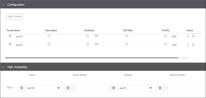
3. Configuration: Allows you to specify different tunnel type (IPsec or GRE) and other tunnel characteristics, such as tunnel name, tracker name, tunnel source, whether the tunnel is attached to a primary or secondary data center (which is specified or discovered later) and advanced options, like IP MTU and other tunnel settings.
4. High Availability: Allows you to choose up to 4 active tunnels or 4 active/standby tunnel pairs by choosing the tunnels defined in the Configuration section under the Active or Backup column. You can also modify traffic ratios for the tunnels.
5. Advanced Settings (if applicable): Allows you to define Zscaler primary or secondary data centers and Zscaler location name if desired and advanced Zscaler settings (XFF Forwarding, Enable IPS Control, etc).
| Tech tip |
| In 20.4/17.4, the only two tunnel types that are offered are Umbrella and Third Party. Zscaler manual tunnels (IPsec or GRE) can be configured using the Third Party option. Starting in 20.5/17.5, the three tunnel types that are offered are Umbrella, Zscaler, and Generic. To configure automatic IPsec or GRE Zscaler tunnels, choose the Zscaler option. Zscaler manual tunnels (IPsec or GRE) can be configured using the Generic option. It is recommended to use automatic tunnels if available. |
Automatic Zscaler Tunnels
Automatic Zscaler Tunnels are supported for IPsec and GRE tunnels. The feature provides a level of automation in configuring tunnels, such as automatic tunnel destination discovery, location registration in ZIA, automatic configuration of authentication parameters, and automatic configuration of L7 health checks. The feature gives you secure and simplified management and allows you to deploy Zscaler tunnels easily across a large number of branches.
| Tech tip |
| vEdge does not support GRE automated tunnels, only manual ones. |
IPsec
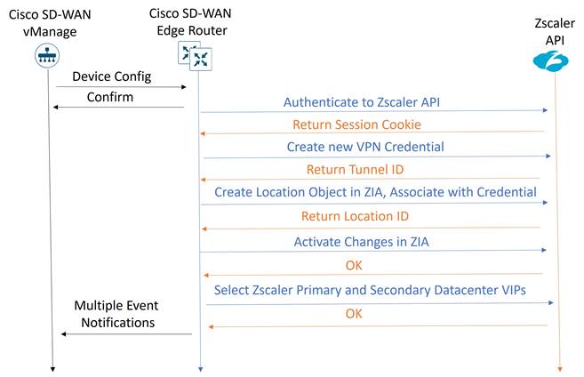
Automatic Zscaler IPsec tunnels are introduced in 20.5/17.5. Once automatic tunnels (through the SIG feature template) and the SIG credentials feature template are added to the device template and are pushed to the WAN Edge device, the following API steps occur from the WAN Edge router to provision the IPsec tunnels.
1. An authenticated session request is made to the ZIA by sending an API key, username, password, and timestamp. A cookie is received which is then used in subsequent calls as part of the authenticated session.
2. VPN credentials are added for each tunnel. Each tunnel has a unique name, FQDN, and pre-shared security key which is generated by the WAN Edge device and then shared to the Zscaler cloud. Zscaler returns a tunnel ID associated with each tunnel. For future edits and modifications, the WAN device refers to the tunnel ID.
3. Next, the VPN credential associated with the tunnel is added to a location before it is usable by Zscaler policy. If it is the first tunnel for a WAN Edge device, a location is created with a unique location name and added to ZIA via an HTTP POST. The tunnel VPN credentials are added to the location.
4. A final API call is done to activate the configuration changes made in ZIA.
5. Primary and secondary data centers are retrieved from ZIA
Another sequence of API calls happens when a tunnel is deleted.
Each API HTTP response is received and the last response code recorded for troubleshooting purposes. Once the APIs are completed, you should end up with a non-zero location ID and non-zero tunnel IDs. Whether the tunnel comes up and active depends on the IKE negotiation. See the Operate section for more information on troubleshooting.
GRE
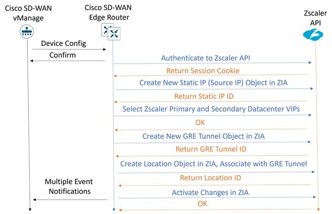
Automatic Zscaler GRE tunnels are introduced in 20.9/17.9. Once automatic tunnels (through the SIG feature template) and the SIG credentials feature template are added to the device template and are pushed to the WAN Edge device, the following API steps occur from the WAN Edge router to provision the GRE tunnels:
1. An authenticated session request is made to the ZIA by sending an API key, username, password, and timestamp. A cookie is received which is then used in subsequent calls as part of the authenticated session.
2. A new static/source IP object is created in Zscaler. Zscaler returns a static IP ID associated with each tunnel.
3. Next, the primary and secondary data centers are chosen from a list of data centers retrieved from Zscaler.
4. A new GRE tunnel object is created in Zscaler which references the static IP object created earlier and configured with the primary and secondary data centers chosen. Zscaler returns a GRE tunnel ID associated with each tunnel. For future edits and modifications, the WAN device refers to the tunnel ID.
5. A new location object is created in Zscaler, and the GRE tunnel is associated with it. Zscaler returns a location ID.
6. A final API call is done to activate the configuration changes made in ZIA.
Another sequence of API calls happens when a tunnel is deleted.
Each API HTTP response is received and the last response code recorded for troubleshooting purposes. Once the APIs are completed, you should end up with a non-zero location ID and non-zero tunnel IDs. The GRE tunnel status should come up. See the Operate section for more information on troubleshooting.
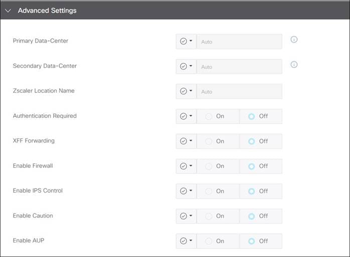
Advanced Settings for Zscaler Auto Tunnels
The following optional Zscaler advanced features can be enabled from the SD-WAN Manager SIG feature template:
● Primary Data center/Secondary Data center: By default, the primary and secondary data centers are automatically selected. Alternatively, the data centers can be manually chosen. If a Global variable is selected, you can choose from a drop-down list of data centers. Before 20.9 code, this list of data centers may be static and the information not completely current. If you choose device specific input, an FQDN is required for the variable for an IPsec tunnel, and a destination IP address is required for the variable for a GRE tunnel. For the latest list of data centers, go to https://config.zscaler.com (then choose the cloud name from the drop-down).
● Zscaler Location Name
● Authentication Required: If enabled, the Surrogate IP feature can be enabled with its corresponding parameters
● XFF Forwarding
● Enable Firewall
● Enable IPS Control
● Enable Caution
● Enable AUP and additional AUP parameters
For additional information on these advanced location features, go to https://help.zscaler.com/zia/configuring-locations.
Layer 7 Health Check for Auto Tunnels
L7 health checks are enabled by default on all auto-tunnels provisioned with the Secure-Internet-Gateway templates.
The L7 health check is implemented as an HTTP request. It measures route-trip latency and compares it to the threshold set. The tracker can be customized if you want to change the default parameters or use a different service URL. The default settings are:
● Interval: 30 seconds
● Multiplier: 2
● Threshold: 1000 msec
● Service URL for Zscaler tunnel type: http://gateway.<zscalercloud>.net/vpntest
For IOS XE SD-WAN, a Loopback 65530 interface in vrf 65530 is created and used to source the L7 health check probes through each active and backup tunnel. It is mandatory for the user to configure a tracker source IP address which is a private RFC 1918 address which should not overlap with other interfaces.
For vEdge, a loopback 65530 in VPN 65530 is created by default, sourced from 192.168.0.2/32. No tracker source IP address needs to be configured for vEdge.
For any tunnels that fail to receive a response within the interval and retransmit timers, or for any tunnels that exceed the latency threshold, the tunnel tracker status is marked down and the VPN routes pointing to this tunnel is marked standby. Crypto IKE stays up for the IPsec tunnel and tunnel status also stays up for the GRE tunnel, but the routes are withdrawn. When the tracker status goes UP (probes become reachable again or latency improves below threshold), the tunnel can become active again and the VPN routes can be added back.
General Configuration Steps
Multiple automatic Zscaler tunnels are implemented by:
● Creating a SIG Credentials feature template for API access to Zscaler (In 20.9 and above, this is done once after creating the first Zscaler SIG feature template; you are prompted with a link to configure the SIG credentials feature template).
● Creating a SIG feature template to define the tracker information, tunnel types, parameters, advanced settings, and high availability information.
● Adding the SIG template and SIG Credentials feature template to the transport VPN (VPN 0) in a device template.
● Adding a SIG Service route in the service VPN or adding centralized data policy to redirect user traffic to the SIG service.
Configuration Prerequisites
For Zscaler automatic tunnels to succeed, the following prerequisites are required:
● Zscaler ZIA GUI needs to be configured with a partner key, username, and password (which belongs to the partner admin role).
● NAT needs to be enabled on the Internet-facing interface on the WAN Edge router. In IOS XE SD-WAN, there is a loopback 65528 in VRF 65528 by default with an IP address of 192.168.1.1 that is used as the source interface for API calls. A NAT DIA route is used to direct API traffic into the underlay.
● A DNS server configuration should exist in the transport VPN (VPN 0) and be reachable from the transport VPN (VPN 0). An Internet DNS server is often used for this purpose. The Zscaler base URI needs to be resolved from the WAN Edge router for API calls, along with the Layer 7 health check URI. The Zscaler base URI is zsapi.<zscalercloud>.net/api/v1 where values for <zscalercloud> are zscaler, zscalerbeta, zscalerone, zscalertwo, zscalerthree, etc. The automated Layer 7 health check URL is http://gateway.<zscalercloud>.net/vpntest.
● The WAN Edge router clock should be accurate (for Zscaler API calls), so configuring Network Time Protocol (NTP) is highly recommended.
Design Considerations
Basic
● NAT is required on each outgoing tunnel WAN interface for API calls to succeed.
● DNS server configuration is required in VPN 0 and reachable from VPN 0 so Zscaler API and L7 heath check URLs can be resolved.
● NTP configuration is highly recommended so clocks are synced to ensure successful API calls.
● Do not change Site ID or System IP Address of a WAN Edge router when you have a SIG feature template attached. Remove the SIG feature template to remove the tunnels, make the Site ID and/or System IP address change, then re-attach the SIG feature template.
ZIA GUI
● When using automated tunnels, it is recommended to avoid making manual changes to the tunnels and locations in the Zscaler GUI as much as possible. Use SD-WAN Manager to make modifications to those parameters.
ECMP Tunnels
● When configuring multiple active/active tunnels, each tunnel is required to have a unique source ip/source port/destination ip/destination port. For multiple, active tunnels over the same transport, you can use loopback interfaces defined in VPN 0 to source multiple active tunnels from. vEdge routers do not support loopback interfaces for tunnel sources.
● There are several applications that are known to fork off multiple sessions for a single user session (O365, Google Services, Facebook, etc). If you have two active SIG tunnels that are pinned to two different Zscaler data centers, Four-tuple ECMP (the default) could pin flows from a single user to separate tunnels. The cloud application could see different client IP addresses for the same session, since NAT is applied to their source IP addresses from two different data centers, and thus, resets from the server could occur. It is required to use the same SIG data center for any active/active tunnels.
● There may be performance implications to applications using active/active tunnels and four-tuple ECMP if the tunnels have significant performance differences. Use source IP-based ECMP to prevent a single-user session from hashing over multiple tunnels.
● Source IP-based ECMP is not supported for vEdge routers. It is supported for IOS XE SD-WAN routers and can be configured only when the WAN Edge router is in CLI mode before version 17.12. If you try to use an add-on CLI template, the ECMP configuration goes back to the default, which is four-tuple. This a affects hardware-based IOS XE SD-WAN routers and is fixed in 17.12.
Auto Tunnels
● There is no support for vEdge auto GRE tunnels.
● When the WAN Edge routers retrieve a list of the closest GRE or IPsec Zscaler data centers through the API, the “withinCountry” flag is set to true. This can impact the ability of the WAN Edge to connect to the closest data center if this device is near the border of a country, and the router could connect to a data center further away (within country). This is addressed in vManage version 20.14.
● There are several advanced security features that can be enabled on Zscaler through APIs from the SD-WAN Manager GUI. It is recommended to leave all features off as default, deploy the feature template, bring the tunnels up, then go back to edit the SIG template and enable the desired features/services. Some features may not have the proper licenses or permissions to enable, so you could get a failed http response and a location may not get created if you are trying to create tunnels at the same time. It simplifies troubleshooting if you enable them separately from configuring tunnels for the first time.
● In SD-WAN Manager version 20.5, values greater than 255 for Idle-time-to-dissociation and Refresh-time (part of Authentication/Surrogate IP feature and Surrogate IP for Known Browser feature) cannot be configured in the SIG template UI. The workaround in IOS XE SD-WAN Edge routers is to use a CLI add-on template. See https://www.cisco.com/c/en/us/td/docs/routers/sdwan/command/iosxe/qualified-cli-command-reference-guide/zscaler-commands.html for additional information on Zscaler advanced features CLI commands. This is fixed in SD-WAN Manager 20.6.
L7 Health Checks
● In the 20.5 SD-WAN Manager version, L7 health checks are supported only for vEdge routers. Health checks are not supported for IOS XE SD-WAN Edge routers until the 20.6 SD-WAN Manager version.
● Starting in 20.5/17.5, manual GRE or IPsec tunnels can be configured using the generic SIG tunnel option in the SIG feature template. L7 health checking is not supported for the generic SIG tunnel option until 20.8/17.8.
● L7 health checks are sent out on all SIG tunnels across all HA configs. L7 health checks can promote a standby tunnel to an active tunnel, potentially impacting existing sessions.
● Do not use custom L7 health check trackers destined to commonly visited websites, because it may cause cloud security provider IP address space to be blocked. Use http://gateway.<zscalercloud>.net/vpntest as the service URL. Only HTTP:// should be used in the service URL to Zscaler. HTTPS:// is not valid, even though the SD-WAN Manager GUI may accept it.
● L7 health checks should not be sent more than one every 5 seconds.
GRE
● GRE tunnel source IP addresses are not affected by NAT/PAT defined on an interface (like IPsec tunnel source IP addresses are). This means that GRE tunnel source IP addresses must either be addressed with a publicly routable IP address or through one-to-one NAT on an external device. Because the tunnel source IP address is used for registration with Zscaler, each GRE tunnel source IP address must be unique and should be static and not change.
● Loopback interfaces as tunnel sources for GRE are not supported until 17.9.2 and higher.
● GRE Keepalives are disabled by default in IOS XE SD-WAN devices. To configure GRE keepalives, a CLI add-on feature template can be configured. The command is keepalive [[seconds] retries] under the tunnel interface configuration. GRE Keepalives do not pass through NAT.
IOS XE SD-WAN
● On an IOS XE SD-WAN router with multiple Internet interfaces accessing Zscaler tunnels or multiple active tunnels sourced by loopbacks on a router with more than one transport of any type, there may be an issue where ISAKMP traffic fails to take the correct interface outbound, which can prevent IPsec tunnel formation. This was fixed 20.8/17.8, but there are still cases where DNS requests for health checks may take an incorrect interface. To work around this, use a CLI add-on policy to use a local Policy-Based Routing (PBR) policy to force DNS or any other local router control traffic to use the proper physical interface (see Deploy section for multiple active/active tunnels).
● As referenced by Field Notice FN72510, Cisco IOS XE Software: Weak Cryptographic Algorithms Are Not Allowed by Default for IPsec Configuration in Certain Cisco IOS XE Software Releases. This affects platforms starting in 17.11.1a and later, and, in a new deployment, will not allow you to configure null encryption for IPsec SIG tunnels. As a workaround, enter crypto engine compliance shield disable in the CLI add-on template or in CLI mode and issue a reload. Cisco does not recommend this option as weak cryptographic algorithms are insecure and do not provide adequate protection from modern threats.
vEdge
● vEdge does not support loopback interfaces for tunnel sources.
● vEdge does not support Zscaler GRE auto tunnels.
● vEdge does not support fallback for data policy for traffic redirection to a SIG tunnel.
● vEdge does not support SIG tunnel monitoring enhancements.
The following basic steps are needed to configure auto tunnels successfully:
● Set up Zscaler Internet Access (ZIA) for API access. This allows SD-WAN Manager to send API calls to ZIA to provision IPsec tunnels and Zscaler locations.
● Deploy Pre-requisites.
Verify NAT, DNS, and clock/NTP settings.
Create a SIG Credentials Feature Template. This uses information obtained from ZIA you configured while setting up ZIA for API access.
If you plan on using Null Encryption, which is the default for Zscaler SIG tunnels, disable crypto compliance by entering crypto engine compliance shield disable in the CLI add-on template or in CLI mode and issue a reload. See Field Notice FN72510. Compliance is enforced starting in 17.11.1a for many platforms and won’t allow you to configure weak cryptographic algorithms. While not recommended, disabling crypto compliance is a workaround in order to use the Null Encryption option.
● Deploy IPsec Auto Tunnel Use Case. There are different use cases you can choose from. Active/Standby tunnels and Active/Active tunnels using hybrid or dual-internet transports and configured with a SIG route or centralized policy are a few examples. For each use case, the following is needed:
Create a SIG Feature Template: This allows you to define multiple tunnels of certain types (Umbrella, Zscaler, or generic), and allows you to define specific characteristics about each tunnel. Then, you can define which tunnels are active and which are backup.
| Tech tip |
| Note that once a tunnel type is selected in the SIG Feature Template, you can only configure additional tunnels of that same type in that specific feature template. With Zscaler tunnels using the SIG template, IPsec or GRE tunnels are both supported, but a mix of both is not supported in the same feature template. L7 health checking is not supported in this code version for generic tunnels. |
Add the SIG and SIG Credentials feature template to the device template of the device you want to configure with IPsec auto tunnels.
Add a route or modify centralized policy for traffic redirection to the Zscaler tunnels.
| Tech tip |
| Before moving forward, ensure that the WAN Edge router has a device template deployed from SD-WAN Manager with, at minimum, basic connectivity to the Internet. Refer to Appendix G for details on a base template example that could be deployed before moving forward. |
Deploy: Zscaler Internet Access (ZIA) for API Access
Note that login IDs and passwords in the following GUI screens may be obscured for security reasons.
Procedure 1. Log into ZIA
Step 1. Log into Zscaler using your administrator account. The login URL is https://admin.<zscalercloud>.net, where <cloud> is equivalent to the Zscaler cloud you have admin rights to (zscalerbeta, zscalerone, zscalertwo, zscalerthree, etc)

Step 2. If you are unable to log in using your administrator account, please contact support at https://help.zscaler.com/submit-ticket.
Procedure 2. Find Zscaler Organization Domain and Partner Base URI
For the SD-WAN Manager SIG Credentials feature template, the Zscaler Organization Domain and Partner Base URI is needed.
Step 1. Go to Administration>Settings>Company Profile. On the Organization tab, copy down the domain name listed under the Domains field (ciscotest.net in this example). If multiple domains exist, select only one of them.
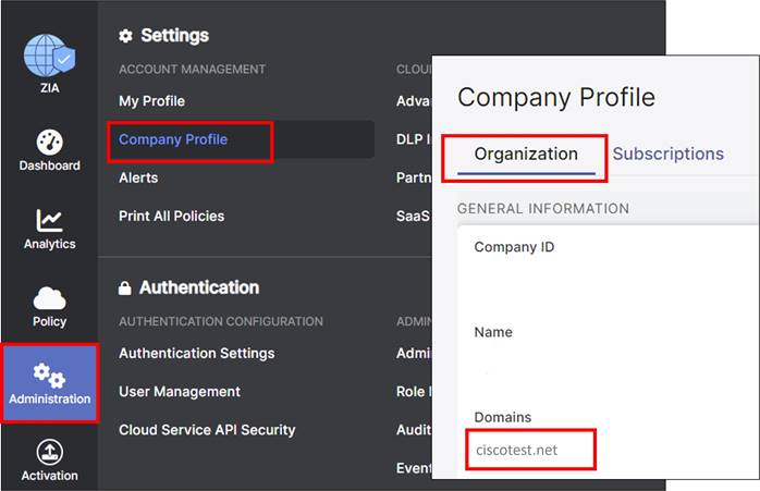
| Tech tip |
| The Domains value in this section is used in the Organization field in the SD-WAN Manager SIG Credentials feature template. |
| SD-WAN Manager SIG Credentials Parameter |
Zscaler GUI Location |
Zscaler Parameter |
Zscaler Value |
| Organization |
Administration>Settings>Company Profile>Organization |
Domains |
ciscotest.net (example) |
Go to Administration>Authentication>Cloud Service API Security. On the Cloud Service API Key tab at the top of the page, copy the base URL for your API (zsapi.zscalerbeta.net/api/v1 in this example).
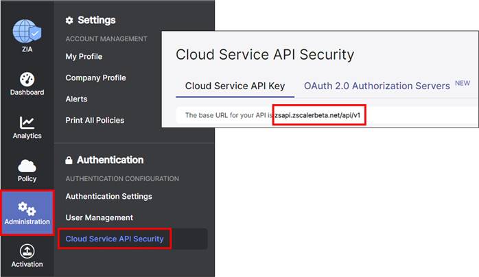
| Tech tip |
| The base URL value in this section is used in the Partner Base URI field in the SD-WAN Manager SIG Credentials feature template. |
| SD-WAN Manager SIG Credentials Parameter |
Zscaler GUI Location |
Zscaler Parameter |
Zscaler Value |
| Organization |
Administration>Company Profile>Organization |
Domains |
ciscotest.net (example) |
| Partner Base URI |
Administration>Authentication>Cloud Service API Security>Cloud Service API Key |
Base URL for your API |
zsapi.zscalerbeta.net/api/v1 (example) |
Procedure 3. Add and Verify SD-WAN Partner Key
To enable ZIA for API access, the first step to be done is to create a SD-WAN “Partner Key”. The partner key is simply an API key, which is used as one form of authentication. The second form of authentication is an admin partner username and password, which is explained further in this deployment guide. This admin credential set can only be used for API calls and does not work to log into the ZIA admin UI.
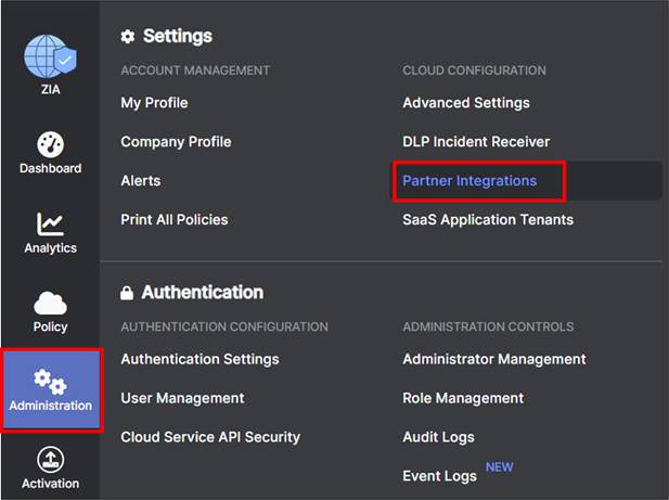
Step 1. Navigate to Administration>Settings>Cloud Configuration>Partner Integrations
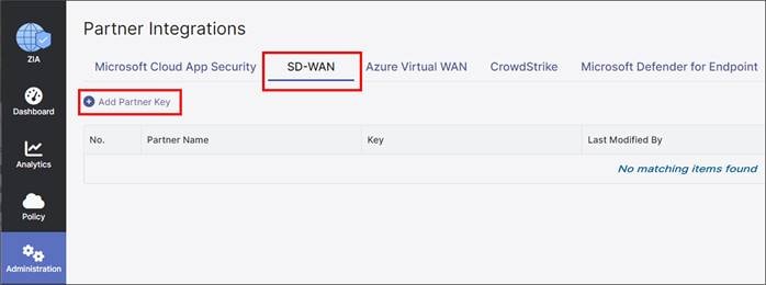
Step 2. At the Partner Integrations section of the ZIA Admin UI, select the SD-WAN tab. If a key already exists with a Partner Name Cisco SD-WAN, then skip to Step 6. Only one key can exist per partner name. Take care when deleting or modifying the partner key since API calls to Zscaler fail if other SD-WAN Manager instances are using the current key.
Step 3. Click Add Partner Key.
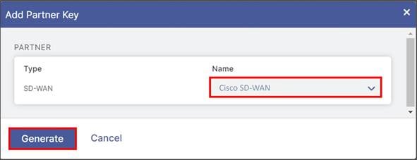
Step 4. Under the Name column on the window that appears, you can select from the drop-down box which SD-WAN vendor you wish to create a partner key for. After selecting Cisco SD-WAN, click on Generate. This returns you to the previous screen.
Step 5. Once you return to the previous screen, you should see the partner key you created for Cisco SD-WAN. You should also see a red circle with a number above the Activation icon on the bottom, left-hand side of the screen. Although we have created a partner key, the configuration change is pending. Only after activation does this configuration become active.
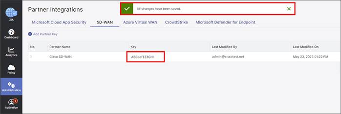
Step 6. Ensure to copy the Key value as it is required in a future step when configuring the SIG Credentials feature template in the SD-WAN Manager NMS.
| Tech tip |
| The Cisco SD-WAN partner Key value in this section is used in the Partner API Key field in the SD-WAN Manager SIG Credentials feature template. |
| SD-WAN Manager SIG Credentials Parameter |
Zscaler GUI Location |
Zscaler Parameter |
Zscaler Value |
| Organization |
Administration>Company Profile>Organization |
Domains |
ciscotest.net (example) |
| Partner Base URI |
Administration>Authentication>Cloud Service API Security>Cloud Service API Key |
Base URL for your API |
zsapi.zscalerbeta.net/api/v1 (example) |
| Partner API Key |
Administration>Settings>Cloud Configuration>Partner Integrations>SD-WAN |
Partner Name (Cisco SD-WAN) Key |
ABCdef123GHI (example) |
Procedure 4. Add a Partner Administrator Role
A partner administrator role needs to be created so it can be assigned to the administrator user that is used to authenticate against the Zscaler ZIA Provisioning API. By creating a partner administrator role, we can define the permissions and access we wish to grant to a third-party partner, such as a SD-WAN partner.
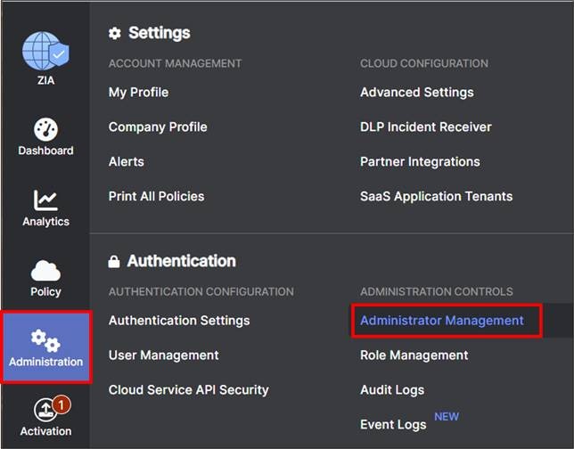
Step 1. Navigate to Administration>Authentication>Administration Controls>Role Management.
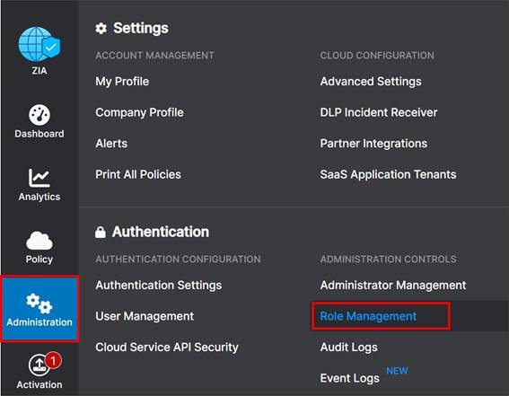
If a partner administrator role has already been created with full access, then you may use this role, or create a separate one. A partner administrator role is listed as Type Partner Admin, and there is a Policy keyword listed under the Full Access column. If you use a role already created, make note of the Name, and go to Procedure 5 to create a partner administrator login ID and password.
Step 2. To create a new Partner Administrator Role, click on Add Partner Administrator Role.
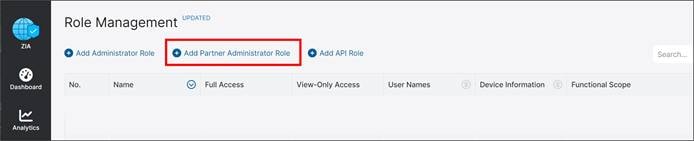
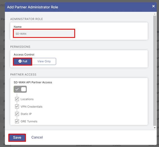
Step 3. Enter the name of the Partner Administrator Role you want to create.
Step 4. Change the Access Control to Full. Full Access Control allows partner admins to view and edit VPN credentials and locations that the SD-WAN Manager NMS is managing via the ZIA Provisioning API. This is necessary for the SD-WAN Manager NMS to be able to create new VPN credentials and locations in ZIA for branches.
Step 5. Click Save to be returned to the previous screen.
Procedure 5. Create a Partner Administrator
The last step required is to create a partner administrator.
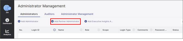
Step 1. Navigate to Administration>Administration Controls and then click Administrator Management.
Step 2. On the Administrator Management page under the Administrators tab, select Add Partner Administrator.
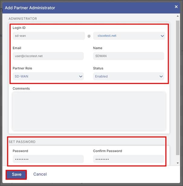
Step 3. An Add Partner Administrator user input screen appears. Once the Add Partner Administrator input box appears, fill in the required fields:
● Login ID (This includes @domain which fills in automatically to the right if there is only one domain with this account. If there are multiple domains associated with this account, choose the correct one from the dropdown.)
● Email: Can be any address in email format and can be equal to the login ID, but cannot already exist in the current cloud (it should not be referenced anywhere)
● Name: Name or label associated with the login ID (it should not be referenced anywhere)
● Partner Role: Role created in Procedure 4.
● Status: Enable or disable the Partner Administrator account. By default, it is enabled.
Note: Save the Login ID@Domain value and Password settings as you need to enter them in the SD-WAN Manager NMS when configuring the SIG Credentials template.
Step 4. Once this is completed, click Save.
| Tech tip |
| The Login ID @ Domain value in this section is used in Username field and the Password value in this section is used in the Password field in the SD-WAN Manager SIG Credentials feature template. |
| SD-WAN Manager SIG Credentials Parameter |
Zscaler GUI Location |
Zscaler Parameter |
Zscaler Value |
| Organization |
Administration>Company Profile>Organization |
Domains |
ciscotest.net (example) |
| Partner Base URI |
Administration>Authentication>Cloud Service API Security>Cloud Service API Key |
Base URL for your API |
zsapi.zscalerbeta.net/api/v1 (example) |
| Username |
Administration>Administration Controls>Administrator Management>Administrators |
Partner Admin Login ID |
sd-wan@ciscotest.net (example) |
| Password |
Administration>Administration Controls>Administrator Management>Administrators |
Partner Admin Password |
(hidden) |
| Partner API Key |
Administration>Settings>Cloud Configuration>Partner Integrations>SD-WAN |
Partner Name (Cisco SD-WAN) Key |
ABCdef123GHI (example) |
Procedure 6. Activate Pending Changes
Note that the new configurations are not enabled until activation occurs.
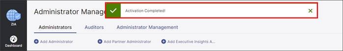
Step 1. Hover over the Activation button on the left-hand side of the screen and click Activate to enable the pending configuration changes.
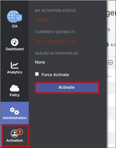
Step 2. After activating pending changes, you should be returned to the prior page, and Activation Complete should appear in the top of the window.
Deploy: Cisco WAN Edge Prerequisites
In this section, the prerequisites are checked and deployed. It includes:
Procedure 1. Log into the Cisco Catalyst SD-WAN Manager
Step 1. Open a web browser and enter the URL for your SD-WAN Manager instance (https://<SD-WAN Manager IP address>:8443). For best results, it is recommended to use a Chrome or Firefox browser.
Step 2. Enter the admin username and password.
Procedure 2. Ensure Prerequisites are met:
Step 1. Verify that NAT is enabled on the Internet interface that is used to access Zscaler.
This is needed for the API calls that are requested against the Zscaler node, since a NAT DIA route is used to direct the API traffic out of the underlay. NAT should be enabled on each Internet interface deployed where Zscaler tunnels are built. The following is the relevant information that is required in the Internet interface feature template:
Modifications to Feature Template: BR_VPN0_INET
| Section |
Parameter |
Type |
Variable/value |
| NAT |
NAT |
Global |
On |
|
|
NAT Type |
Global |
Interface |
Step 2. Verify that a primary and/or secondary DNS server is defined in the VPN 0 feature template. API calls are made to the base URI: zsapi.<zscalercloud>.net/api/v1 or admin.<zscalercloud>.net/api/v1 where values for <zscalercloud> are zscaler, zscalerbeta, zscalerone, zscalertwo, zscalerthree, etc. The automated Layer 7 health check URL also needs DNS resolution. It is http://gateway.<zscalercloud>.net/vpntest.
| Tech tip |
| Note that the DNS servers you define in VPN0 must be reachable from VPN0. Internet DNS servers are often used for this purpose. |
The following is the relevant feature template information that is required (which can be global or device specific values):
Modifications to Feature Template: BR_VPN0
| Section |
Parameter |
Type |
Variable/value |
| DNS |
Primary DNS Address (IPv4) |
Global |
208.67.222.222 |
|
|
Secondary DNS Address (IPv4) |
Global |
208.67.220.220 |
Step 3. Verify NTP is enabled, synced, and the clock is correct. One reason an authentication session can fail with Zscaler is due to the clock time being mismatched. Configuring NTP and ensuring the NTP server time is synced is one way to prevent authentication issues.
WAN_EdgeE#show clock
01:49:13.091 UTC Fri Sep 3 2021
WAN_EdgeE#show ntp association
address ref clock st when poll reach delay offset disp
*~64.100.100.1 127.127.1.1 5 157 1024 377 3.000 -3.500 2.050
* sys.peer, # selected, + candidate, - outlyer, x falseticker, ~ configured
NTP is configured in a separate feature template and added to the device template in the basic information section. In the example topology, the source interface is the Internet interface in VPN 0, since the NTP server is on the Internet.
Feature Template Name: NTP
| Section |
Parameter |
Type |
Variable/value |
|
|
|
|
|
| Server |
Hostname/IP address |
Global |
time.google.com |
|
|
Source Interface |
Device Specific |
ntp_server_source_int |
Procedure 3. Create a SIG Credentials Feature Template
Starting in 20.9 SD-WAN Manager code versions, the SIG credentials feature template is created automatically and is filled out only one time when a SIG feature template is first created with a specific SIG provider and software platform (vEdge or IOS XE SD-WAN). The credentials template is then added automatically to a device template when the SIG feature template is added. Before the 20.9 SD-WAN Manager code version, there is a SIG credentials feature template you must create and configure separately and then manually add to a separate section of the device template when the SIG template is added.
If using 20.9 SD-WAN Manager code and above, create the first Zscaler SIG feature template to create the global Zscaler SIG credentials feature template. If using 20.8 SD-WAN Manager code and below, create a separate SIG Credentials feature template.
Step 1. In the top left corner of SD-WAN Manager, click the 3 horizontal lines to pull down the menu.
Step 2. Select Configuration>Templates and click the Feature or Feature Templates button at the top right of the page.
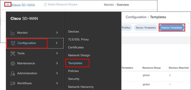
Step 3. Click Add Template
Step 4. Select devices on the last-hand side that potentially can use this template. To select all IOS XE SD-WAN devices that can support SIG Templates, you can select all platforms except for ISR 1100 (Viptela OS), vEdge devices, CG platforms, the IR8140 and IR8340, and the vManage and vSmart from the device model list (in the 20.9 release).
Step 5. In SD-WAN Manager version 20.9 and above, select Cisco Secure Internet Gateway (SIG) under the VPN section.
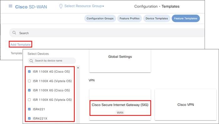
In other SD-WAN Manager versions, select Cisco SIG Credentials under the Other Templates section.
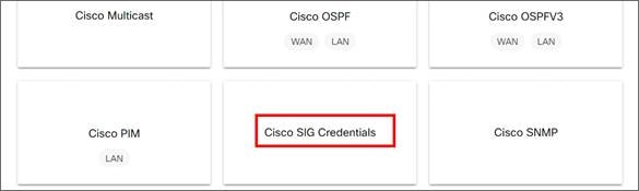
Step 6. In SD-WAN Manager version 20.9 and above, in the Cisco Secure Internet Gateway (SIG) feature template, select the Zscaler SIG Provider, then click Click here to create – Cisco SIG Credentials template.
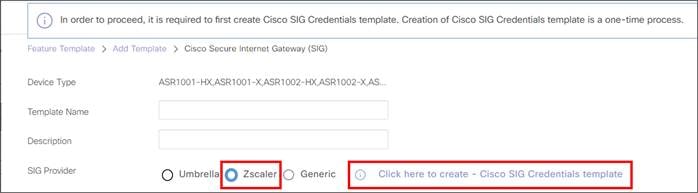
Step 7. In SD-WAN Manager version 20.9 and above, the Template Name (Cisco-Zscaler-Global-Credentials) and Description (Global credentials for zscaler) are already filled in, and the SIG Provider is already selected (Zscaler).
In other SD-WAN Manager versions, Enter the Template Name (xeSig_Credentials) and Description (IOS XE Sig Credentials Template) and Next to SIG Provider, select the Zscaler radio button.
Step 8. Fill in the Organization, Partner Base URI, Username, Password, and Partner API Key. These parameters were obtained from the Zscaler configuration section:
| SD-WAN Manager SIG Credentials Parameter |
Zscaler GUI Location |
Zscaler Parameter |
Zscaler Value |
| Organization |
Administration>Company Profile>Organization |
Domains |
ciscotest.net (example) |
| Partner Base URI |
Administration>Authentication>Cloud Service API Security>Cloud Service API Key |
Base URL for your API |
zsapi.zscalerbeta.net/api/v1 (example) |
| Username |
Administration>Administration Controls>Administrator Management>Administrators |
Partner Admin Login ID |
sd-wan@ciscotest.net (example) |
| Password |
Administration>Administration Controls>Administrator Management>Administrators |
Partner Admin Password |
(hidden) |
| Partner API Key |
Administration>Settings>Cloud Configuration>Partner Integrations>SD-WAN |
Partner Name (Cisco Viptela) Key |
ABCdef123GHI (example) |
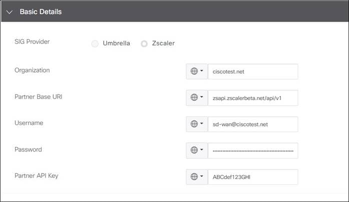
Step 9. Click Save. The Zscaler SIG credentials feature template has been created.
Step 10. For SD-WAN Manager versions 20.9 and higher, you return back to a SIG feature template where you can continue to configure a SIG template, or click cancel to configure a SIG template at a later time.
Deploy: Cisco WAN Edge Auto IPsec or GRE Tunnels (One Active/Standby Pair, Hybrid Transport)
In this section, one active/standby auto tunnel pair is configured on the Internet transport, one to the primary Zscaler data center and one to the secondary Zscaler data center. Traffic is forwarded on the active tunnel to the primary data center until the active tunnel is declared to be down (through L7 health checking and/or Dead Peer Detection). Once down, the standby tunnel to the secondary DC becomes active. When the tunnel to the primary DC recovers, it becomes active again and the tunnel to the secondary DC goes into standby.
The following deployment use case contains the following features:
● One Active/Standby IPsec or GRE Auto Tunnel Pair on a single Internet transport. The Active tunnel connects to a primary Zscaler DC and the Standby tunnel connects to a secondary Zscaler DC.
● SIG Service Route for redirecting traffic to Zscaler tunnels
● Customized L7 Health Tracker (optional)
● Advanced Zscaler Features (optional)
● Customized Zscaler Tunnel Destinations (optional)
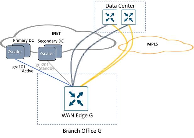
Procedure 1. Create a SIG Template.
Step 1. On the Configuration>Templates>Feature Templates page, click Add Template, select devices and under VPN, select Cisco Secure Internet Gateway (SIG).
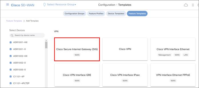
Step 2. Enter the Template Name (xeSig_Zscaler) and Description (IOS XE Sig Zscaler Template).
Step 3. Next to SIG Provider, select the Zscaler radio button.
Step 4. (IOS XE SD-WAN ONLY) A source IP address for the L7 Health Tracker is required. This field is a private, unique IPv4 address with a /32 prefix. Under the Tracker (Beta) section next to Source IP Address, choose Device Specific from the drop down. The variable for this parameter is labeled zscaler_trackersrcip. Note that this field IS required for IOS XE SD-WAN routers. You can turn off health checks under the tunnel configuration advanced settings (not recommended), but you must still configure a global value or device specific variable for the Tracker Source IP Address.
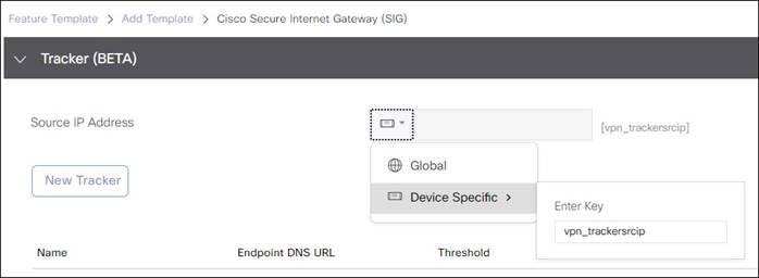
Note that by default, vEdge routers use source IP address 192.168.0.2 in vrf 65530 for the L7 health tracker.
A tracker does not need to be explicitly configured for SD-WAN routers because it will be created automatically. By default, L7 health checks are enabled on each tunnel with the following default properties:
| Section |
Parameter |
Type |
Variable/value |
| Tracker |
Threshold (msec) |
Default |
1000 |
|
|
Interval (sec) |
Default |
30 |
|
|
Multiplier |
Default |
2 |
|
|
API url of endpoint |
Default |
http://gateway.<zscalercloud>.net/vpntest |
If you choose to change any tracker parameters, a custom tracker needs to be configured. A customized tracker configuration is shown in Procedure 5.
Step 5. Under the Configuration section, click Add Tunnel.
Step 6. Next to Tunnel Type, select ipsec or gre. The default is ipsec. Once you choose a tunnel type, any additional tunnels configured in the SIG template are automatically chosen to be the same type. GRE is used in this example.
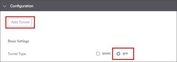
Step 7. For Interface Name, use the global parameter type. Specify an Interface Name, which is the keyword ipsec or gre, followed by a number 1-255 (example: ipsec1 or gre1). Name the interface gre101.
Step 8. Next to Description, choose Global parameter and type an optional Description (Primary DC Tunnel 1)
Step 9. Next to Tunnel Source Interface, select Device Specific and create a variable for this parameter (pri_tunnel1_src_int).
Step 10. Next to Data-Center, select which data center this tunnel will be terminated (Primary). Each Data center location (primary or secondary) will be selected automatically when the configuration is deployed, or can be assigned manually in a later section.
Step 11. (GRE only) GRE tunnels must register their public source IP address through the API calls. Next to Source Public IP, select Device Specific and create a variable for this parameter (pri_tunnel1_src_public_ip).
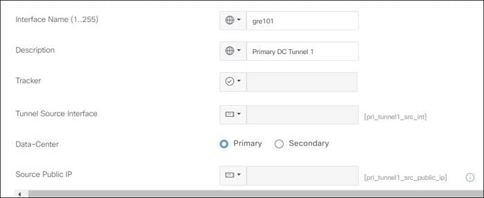
Step 12. Leave the parameters under Advanced Options as defaults. Under Advanced Options, the following default options are set for IPsec tunnels (shown in the first table) and GRE tunnels (shown in the second table).
Table 1. IPsec Tunnel Default Options
| Section |
Parameter |
Type |
Variable/value |
| Advanced Options>General |
Shutdown |
Default |
No |
|
|
Track this interface for SIG |
Default |
On |
|
|
IP MTU |
Default |
1400 |
|
|
DPD Interval |
Default |
10 |
|
|
DPD Retries |
Default |
3 |
| Advanced Options>IKE |
IKE Rekey Interval (seconds) |
Default |
14400 |
|
|
IKE Cipher Suite |
Default |
AES 256 CBC SHA1 |
|
|
IKE Diffie-Hellman Group |
Default |
2 1024-bit modulus |
| Advanced Options>IPsec |
IPsec Rekey Interval (seconds) |
Default |
3600 |
|
|
IPsec Replay Window |
Default |
512 |
|
|
IPsec Cipher Suite |
Default |
Null SHA1** |
|
|
Perfect Forward Secrecy |
Default |
None |
| Tech tip |
| ** As referenced by Field Notice FN72510, Cisco IOS XE Software: Weak Cryptographic Algorithms Are Not Allowed by Default for IPsec Configuration in Certain Cisco IOS XE Software Releases. This affects platforms starting in 17.11.1a and later, and, in a new deployment, will not allow you to configure null encryption for IPsec SIG tunnels. As a workaround, enter crypto engine compliance shield disable in the CLI add-on template or in CLI mode and issue a reload. Cisco does not recommend this option as weak cryptographic algorithms are insecure and do not provide adequate protection from modern threats. |
Table 2. GRE Tunnel Default Options
| Section |
Parameter |
Type |
Variable/value |
| Advanced Options>General |
Shutdown |
Default |
No |
|
|
Track this interface for SIG |
Default |
On |
|
|
IP MTU |
Default |
1400 |
Step 13. Click Add.
Step 14. In this use case, one additional tunnel is created (the standby tunnel to the secondary data center). Click Add Tunnel. For IPsec, use the following settings:
Table 3. Settings for Secondary IPsec Tunnel
| Parameter |
Type |
Variable/value |
|
| Configuration |
Interface Name (1..255) |
Global |
ipsec201 |
|
|
Description |
Global |
Secondary DC Tunnel 1 |
|
|
Tunnel Source Interface |
Device Specific |
sec_tunnel1_src_int |
|
|
Data-Center |
Radio Button |
Secondary |
For GRE, use the following settings:
| Section |
Parameter |
Type |
Variable/value |
| Configuration |
Interface Name (1..255) |
Global |
gre201 |
|
|
Description |
Global |
Secondary DC Tunnel 1 |
|
|
Tunnel Source Interface |
Device Specific |
sec_tunnel1_src_int |
|
|
Data-Center |
Radio Button |
Secondary |
|
|
Source Public IP |
Device Specific |
sec_tunnel1_src_public_ip |
Step 15. Click Add.
Step 16. Repeat steps 5-11 for any additional tunnels needing to be defined.
Step 17. When you are finished adding tunnels, configure which interface you want to be active and backup. Under High Availability, next to Pair-1 under the Active column, select gre101 or ipsec101 from the drop-down menu, and under the Backup column, select gre201 or ipsec201.
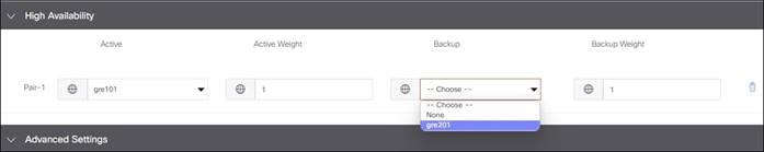
Step 18. In Advanced Settings, you can choose the primary and secondary data centers (the default is automatic). You also have the ability to turn on several Zscaler features for the tunnel through the APIs. They include: Zscaler Location Name, Authentication Required, XFF Forwarding, Enable Firewall, Enable IPS Control, Enable Caution, and Enable AUP. For more information on these options, see https://help.zscaler.com/zia/configuring-locations in the Gateway Options section.
| Tech tip |
| Outside of Zscaler Location Name, do not turn on other Zscaler options under Advanced Settings when bringing tunnels up for the first time. Leave the defaults (off) to bring the tunnels up, then once up, go back and make feature template changes to turn desired features on. Certain features may require certain subscriptions or licenses on Zscaler, and it can make troubleshooting more difficult if you turn some of the features on before bringing tunnels up for the first time. |
Step 19. Under Advanced Settings, keep the defaults and click Save at the bottom of the screen to save the feature template.
Procedure 2. Add the Tunnel Configuration to the Device Template:
Step 1. In SD-WAN Manager, go to Configuration>Templates and select the Device Templates tab. To the right of the device template you want to modify, click … and select Edit from the drop-down menu.
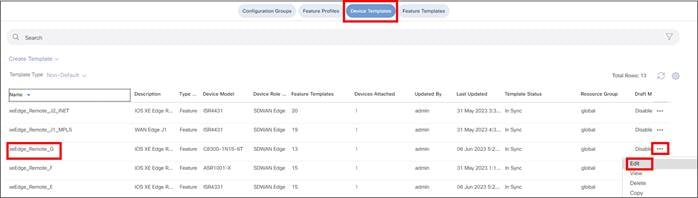
Step 2. Under the Transport & Management VPN section, select Cisco Secure Internet Gateway on the right-hand side. The Cisco Secure Internet Gateway field is then inserted into the Transport & Management VPN section. In the drop-down box, select the SIG feature template recently created (xeSig_Zscaler).
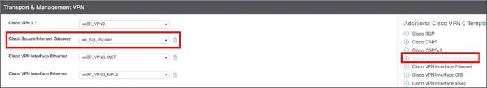
Step 3. Before the device template can be saved, the SIG Credentials template needs to be attached. In SD-WAN Manager version 20.9 and above, this is done automatically when a SIG feature template is attached to the device template. If running a lower SD-WAN Manager version, next to Cisco SIG Credentials *, attach the SIG credentials feature template that was built in the pre-requisites section.
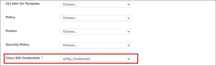
Step 4. Click Update.
Step 5. To the right of the device configuration being updated, click … and select Edit Device Template from the drop-down list.
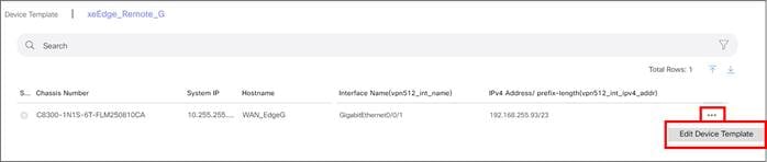
Step 6. Fill in the missing variable values. Fill in the source interface for the primary and secondary tunnels and which physical interface the tunnel should be routed through (this is especially important if the source interface is a loopback interface). If you have configured a GRE tunnel, specify the source public IP address for the tunnel that should be registered on Zscaler. Fill in the source IP address for the L7 health check. Click Update.
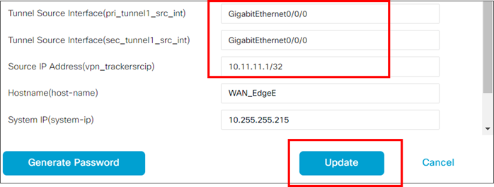
Step 7. Deploy template changes: click Next, then Configure Devices. The configuration changes are pushed and SD-WAN Manager returns success.
Procedure 3. Add Service Route
The last step is to redirect traffic. In this section, a SIG service route (default route) is installed into the service VPN to direct service-side Internet traffic to Zscaler. You can configure this in all service VPN templates where traffic needs to be redirected. The SIG service route is not an optional setting, but if there is not a SIG tunnel up and operational on the router, the route is not installed. So, you can either modify the service VPN template currently in use or create a separate service VPN template for routers that use the SIG service route. In this example, the current service VPN feature template is modified.
Step 1. On the Configuration>Templates page in SD-WAN Manager, click the Feature Templates tab and find the branch service VPN feature template that needs to be modified (xeBR_VPN1).
Step 2. To the right of the feature template, click … and select Edit from the drop-down list.
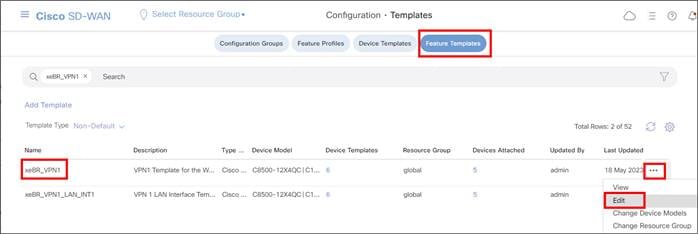
Step 3. Click on the Service Route tab to be brought to the section that needs modification.
Step 4. Click the New Service Route button.
Step 5. Next to Prefix, type 0.0.0.0/0. The Service defaults to SIG. Click Add to add the service route to the configuration, then click Update to save the xeBR_VPN1 feature template.
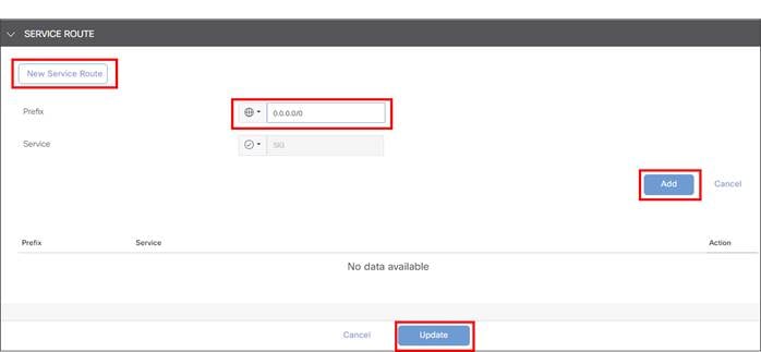
Step 6. Click Next, then Configure Devices. Confirm changes on multiple devices if needed and click OK. The status of the configuration change comes back with Success.
Procedure 4. Verify Tunnel Operation
Step 1. In the SD-WAN Manager GUI under Monitor>Tunnels, click the SIG Tunnels tab to view the tunnel status and any events related to the SIG tunnel.
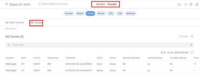
Step 2. In the SD-WAN Manager GUI under Monitor>Devices, click the WAN Edge router that you want to verify the tunnel operation on.
Step 3. Under Applications>Interface, click Real Time at the top right of the chart. You can also click the interface you are interested in on the right-hand side of the chart.
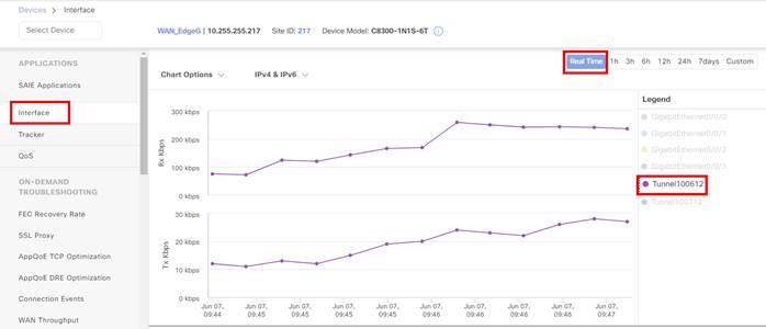
Step 4. If the interface you are interested in is missing from the graph, scroll down past the chart to see the entire list of interfaces. Click the checkbox on the left for the interface you want to display on the chart. You can also view the state and statistics of the various interfaces on the device from this list.
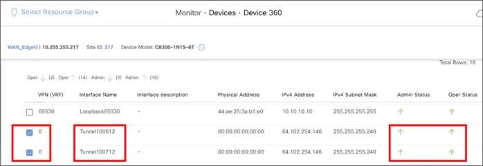
See the Operate section for additional monitoring and troubleshooting information.
Procedure 5. (optional) Customize L7 Health Tracker
In this section, the L7 health tracker is customized.
Step 1. In the SD-WAN Manager GUI, go to Configuration>Templates and click the Feature Templates tab. To the right of the SIG feature template that was created in the earlier section (xeSig_Zscaler), click … and select Edit from the drop-down menu.
Step 2. In the Tracker (Beta) section, click the New Tracker button. Next to Name, select Global for the parameter and enter the name for the tracker (zscaler_l7_health_check), which will be a label referenced by each tunnel using the tracker.
Step 3. For Interval, the default is 60 seconds and the minimum allowed is 20 seconds. Change the parameter to Global, and type 20. For the API url of endpoint, type http://gateway.<zscaler cloud>.net/vpntest for the specific Zscaler cloud you belong to.
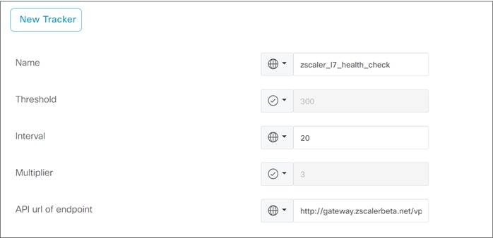
Step 4. Click Add.
Step 5. Now, before finishing the update to the feature template, the new L7 tracker needs to be referenced by the tunnels already created.
Under Configuration next to each tunnel, click the Edit action.
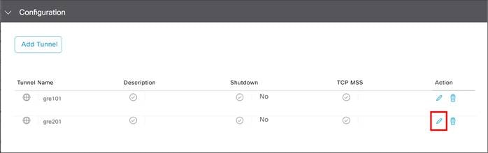
Step 6. Next to Tracker, choose the Global parameter, then in the drop-down box, select the L7 health check you created, zscaler_l7_health_check. Click Save Changes.
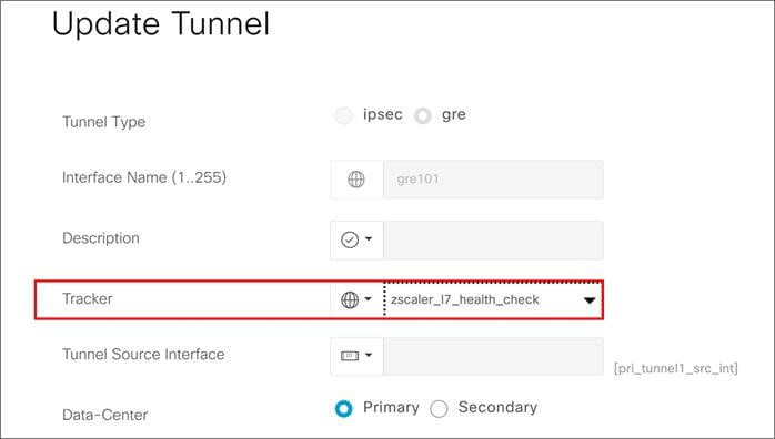
Step 7. Repeat steps 5 and 6 with each tunnel.
Step 8. Click Update to save changes to the SIG feature template. Click Next, then Configure Devices. You may need to confirm configuration changes on multiple devices. Click the checkbox and click OK. The configuration changes are pushed out to the attached WAN Edge routers. The status comes back Success.
WAN_EdgeG#show endpoint-tracker
Interface Record Name Status RTT in msecs Probe ID Next Hop
Tunnel100612 zscaler_l7_health_chec Up 10 25 None
Tunnel100712 zscaler_l7_health_chec Up 77 26 None
Procedure 6. (optional) Enable Advanced Zscaler Features
Step 1. In the ZIA UI, you can view what gateway options are enabled for a location by navigating to Administration>Resources>Location Management and editing the location you are interested in. To change the Gateway options, they should be modified via APIs from the SD-WAN Manager UI.
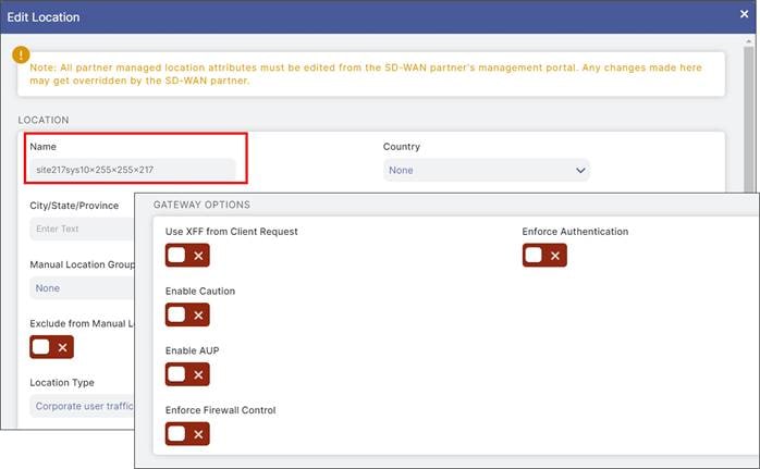
Step 2. To change the settings, modify the SIG Template feature template in the SD-WAN Manager GUI. Go to Configuration>Templates and click the Feature Templates tab. Find the name of the SIG Template you want to modify (xeSig_Zscaler). Click … to the far right of the template and select Edit from the drop-down menu.
Step 3. Under Advanced Settings, select Global parameter and click On next to the settings you want to enable. In this example, Enable Caution is enabled.
Step 4. Click Update.
Note: This will enable the same Zscaler advanced settings for every device this template is attached to. If you need different settings for different devices, a separate SIG feature template is required.
Step 5. Click Next, then Configure Devices. Confirm configuration on multiple devices if needed. Configuration changes are pushed to the devices and Success is returned.
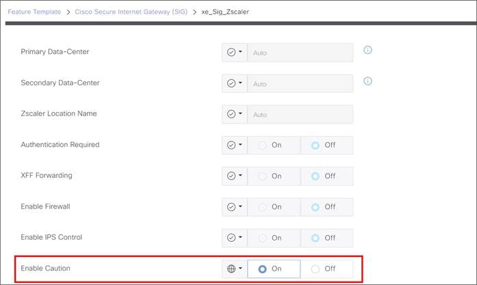
Step 6. View the location gateway options in the ZIA GUI for changes.
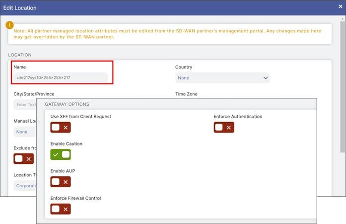
Procedure 7. (optional) Customize Zscaler Tunnel Destination (Primary and Secondary DCs)
It is recommended to use the automation to determine the primary and secondary Zscaler data centers, but if you want to change the tunnel destination settings to choose your own primary and secondary Zscaler DC locations, modify the SIG Template feature template.
Step 1. Go to Configuration>Templates and click the Feature Templates tab. Find the name of the SIG Template you want to modify (xeSig_Zscaler). Click … to the far right of the template and select Edit from the drop-down menu.
Step 2. Under Advanced settings, next to Primary Data-Center, select the Device Specific parameter and use the variable vpn_zlsprimarydc. Next to Secondary Data-Center, select Device Specific and use the variable vpn_zlssecondarydc.
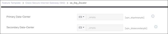
Step 3. Click Update to save the feature template settings.
| Tech tip |
| If you select a Global parameter, you get a drop-down box with available Zscaler data centers to choose from. You should select a DC that is part of your assigned Zscaler cloud. In earlier versions of code, this list of data centers was static and thus, not fully up to date. Use a Device Specific parameter if you need to specify a data center that is not in the list or you need to specify different data centers for different devices attached to the same feature template. To get the most up-to-date list of Zscaler data centers, check: https://config.zscaler.com/<zscalercloud>.net/cenr. In this example, the list for Zscaler cloud Beta is located at https://config.zscaler.com/zscalerbeta.net/cenr. Note that if you use a variable to specify a data center that is not in the recommended list for that location, then a data center will be chosen automatically. |
Step 4. At the top of the page, select a device template you need to fill in data center values for if there is more than one device attached to the SIG feature template. To the right of the device, click on … and select Edit Device Template from the drop-down menu.
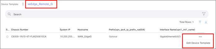
Step 5. Fill in the values for the Primary and Secondary Data-Centers. Use VPN Host names for IPsec tunnel destinations and IP addresses for GRE tunnel destinations. Note that auto is an acceptable value for those locations where the tunnels are automatically discovered for you. This example uses the data center locations Frankfurt IV (165.225.72.38) for primary and Washington, DC (104.129.194.38)) for secondary.
| Tech tip |
| If you are filling in values for primary and secondary data center variables, use IP addresses for GRE tunnel destinations and VPN host names for IPsec tunnel destinations. If IPsec tunnels were being used instead, the example would use data center locations Frankfurt IV (fra4-vpn.zscalerbeta.net) for primary and Washington, DC (was1-vpn.zscalerbeta.net) for secondary. |
Step 6. Click Update.
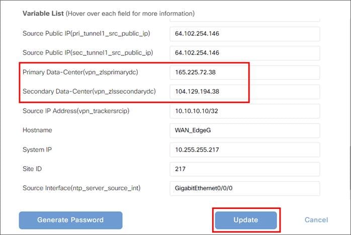
Step 7. Update variable values on any other devices attached to any device templates using the feature template you just modified.
Step 8. Click Next, then Configure Devices. Confirm configuration changes on multiple devices if needed. SD-WAN Manager pushes the configuration changes and indicates Success.
Step 9. Bring up a client browser at the site and navigate to http://ip.zscaler.com. Validate that the Frankfurt IV primary data center is being used.
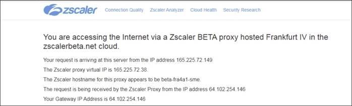
Deploy: Cisco WAN Edge Auto IPsec or GRE Tunnels (Active/Active Tunnels, Hybrid Transport)
In this section, two active auto IPsec tunnels are configured, all to the same Zscaler data center. Traffic is forwarded on both tunnels to the primary data center until a tunnel is declared to be down (through L7 health checking and/or Dead Peer Detection). Once down, traffic is hashed to the remaining tunnel. When the downed tunnel recovers, it becomes active again and traffic can be hashed to it again.
The following deployment use case contains the following features:
● One Active/Active IPsec or GRE Auto Tunnel Pair on a single Internet transport. Both tunnels connect to the same primary Zscaler DC
● ECMP based on source IP address
● Centralized Data Policy for redirecting traffic to Zscaler tunnels
● Weighted Tunnels
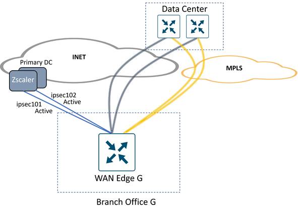
| Tech tip |
| This use case is designed to illustrate how to configure multiple active/active tunnels over a single Internet transport. You can add additional active tunnels (up to 4) or add standby tunnels for any active tunnel as well. With 4-tuple ECMP hashing, you want to keep all active tunnels pointing to the same Zscaler DC. If you choose to implement standby tunnels, you will want them pointing to the same Zscaler DC as the active tunnels in the event one or a subset of standby tunnels become active. You do not want equal cost paths where the same user application session can hash to different Zscaler DCs. Alternatively, use Source IP-based ECMP hashing, which removes this restriction. |
To accommodate both tunnels to one Zscaler destination, 2 loopback interfaces are needed for source IP addresses since each tunnel needs a unique source IP/source port/destination IP/destination port pair.
Procedure 1. (IOS XE SD-WAN only) Create two loopback interfaces, one for each active tunnel
Step 1. In the SD-WAN Manager GUI, navigate to Configuration>Templates and click the Feature Templates tab. Click Add Template, select your devices, and under VPN, select Cisco VPN Interface Ethernet.
Step 2. Enter a Template Name and Description. Under basic configuration next to Shutdown, choose Global parameter and click No. Next to Interface Name, enter Loopback1, and next to IPv4 Address/prefix-length, choose Global parameter and type the address (10.10.10.1/32 in this example). Click Save.
| Tech tip |
| Loopback interfaces used as the source for GRE tunnels need to be addressed with a unique public IP address or a unique private IP address so one-to-one NAT can happen with an external device. You may decide to use device-specific variables rather than global parameters for this reason. |
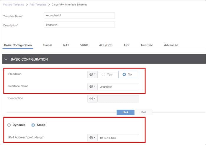
Step 3. Click Save.
Step 4. Copy the previous template and make modifications or create new Interface Ethernet feature templates by repeating the above steps to create 2 total loopback addresses with the following characteristics:
Template Type: Feature Template>Cisco VPN Interface Ethernet
| Feature Template Name |
Section |
Parameter |
Type |
Variable/value |
| Basic Configuration |
Shutdown |
Global |
No |
|
|
|
|
Interface Name |
Global |
Loopback1 |
|
|
|
IPv4 |
Radio Button |
Static |
|
|
|
IPv4 Address/prefix-length |
Global |
10.10.10.1/32 |
| Loopback2 |
Basic Configuration |
Shutdown |
Global |
No |
|
|
|
Interface Name |
Global |
Loopback2 |
|
|
|
IPv4 |
Radio Button |
Static |
|
|
|
IPv4 Address/prefix-length |
Global |
10.10.10.2/32 |
Procedure 2. (IOS XE SD-WAN only) Create a local policy-based routing policy
Create a CLI add-on template that configures a local policy-based routing policy. This is so that control traffic generated by the router picks the proper next-hop interface.
Step 1. If a CLI add-on feature template has already been created, edit the feature template and go to step 3. To create a new one, go to Configuration>Templates. Click the Feature Templates tab and click Add Template. Select the devices the feature template can apply to. Under Other Templates, click Cli Add-on Template.
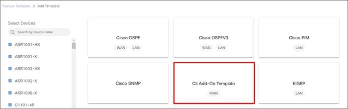
Step 2. Type a Template Name (CLI-Template) and Description (CLI Add-on Template)
Step 3. Add the following CLI:
ip access-list extended SIG
10 permit ip host 10.10.10.1 any
20 permit ip host 10.10.10.2 any
!
route-map Tunnel-Control permit 10
match ip address SIG
set ip next-hop 64.100.217.1
ip local policy route-map Tunnel-Control
Step 4. Highlight 64.100.217.1 as the next-hop and click (x) Create Variable.
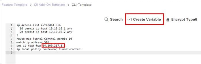
Step 5. In the pop-up window, enter a variable name (Loopback-Tun-Src-Next-Hop-IP). This CLI template could apply to several WAN Edge routers. Click Create Variable.
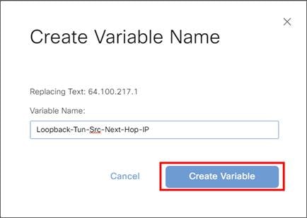
Step 6. Click Save/Update.
Procedure 3. (IOS XE SD-WAN only) Configure Source IP-Based ECMP (optional)
| Tech tip |
| In this version of code, source IP-based ECMP can be configured only when the WAN Edge router is in CLI mode. You first change the WAN Edge router to CLI mode and then you can configure the ip cef load-sharing algorithm src-only command. You must then keep the router in CLI mode. If you try to use an add-on CLI template (or any device template), the ECMP configuration goes back to the default, which is four-tuple. This seems to affect hardware-based IOS XE SD-WAN routers and is fixed in 17.12. |
To configure Source IP-Based ECMP, use the CLI add-on template (IOS XE SD-WAN version 17.12 or greater).
Step 1. Edit the CLI add-on feature template created or modified in Procedure 2.
Step 2. On a separate line in the configuration, enter the command ip cef load-sharing algorithm src-only.
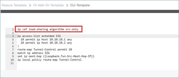
Step 3. Click Update.
Procedure 4. (IOS XE SD-WAN only) Create a new SIG feature template with 2 active tunnels
The active tunnels reference loopback interfaces as sources.
Step 1. In the SD-WAN Manager GUI, navigate to Configuration>Templates and click on Feature Templates. Click Add Template, select the devices the feature template can apply to. Under VPN, select the Cisco Secure Internet Gateway (SIG) template. Add the Template Name (xeSig_Zscaler_2_Loopback_Source) and Description (Sig Zscaler 2 Tunnels with Loopback Source).
Step 2. Next to SIG Provider, select the Zscaler radio button.
Step 3. Under Tracker (BETA), select Device Specific and use the variable given, vpn_trackersrcip.
Step 4. Under Configuration, click Add Tunnel.
Step 5. Next to Tunnel Type, select ipsec or gre. The default is ipsec. Once you choose a tunnel type, any additional tunnels configured in the SIG template are automatically chosen to be the same type. IPsec is used in this example.
Step 6. Next to Interface Name, use the global parameter type. Specify an Interface Name, which is the keyword ipsec or gre, followed by a number 1-255 (example: ipsec1 or gre1). Name the tunnel ipsec101.
Step 7. Next to Description, choose Global parameter and type an optional Description (Primary DC Tunnel 1)
Step 8. Next to Tunnel Source Interface, select Device Specific and create a variable for this parameter (pri_tunnel1_src_int).
| Tech tip |
| Before version 20.8/17.8, if you are using loopback interfaces as a Tunnel Source Interface, use a global parameter. When you specify a loopback interface, a Tunnel Route-via Interface field is added to the feature template so you can specify which physical interface is associated with which loopback interface. This directs data traffic out the proper interface. |
Step 9. Next to Data-Center, select which data center this tunnel will be terminated (Primary). Each data center location (primary or secondary) will be selected automatically when the configuration is deployed, or it can be assigned manually in a later section.
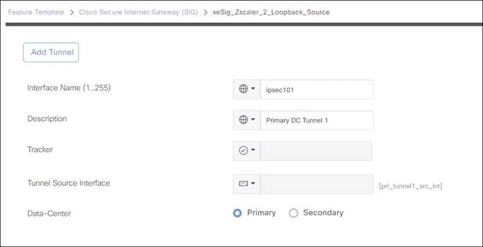
Step 10. (GRE only) GRE tunnels must register their public source IP address through the API calls. Next to Source Public IP, select Device Specific and create a variable for this parameter (pri_tunnel1_src_public_ip).
Step 11. Leave the parameters under Advanced Options as defaults.
Step 12. Click Add.
Step 13. Finish configuring the tunnel interfaces by repeating the above steps to configure 2 tunnels total with the following characteristics. All active tunnels point to the primary data center.
| Section |
Parameter |
Type |
Variable/Value |
| Interface Name |
Global |
ipsec101 |
|
|
|
Description |
Global |
Primary DC Tunnel 1 |
|
|
Tunnel Source Interface |
Device Specific |
pri_tunnel1_src_int |
|
|
Data-Center |
Radio Button |
Primary |
| Configuration |
Interface Name |
Global |
Ipsec102 |
|
|
Description |
Global |
Primary DC Tunnel 2 |
|
|
Tunnel Source Interface |
Device Specific |
pri_tunnel2_src_int |
|
|
Data-Center |
Radio Button |
Primary |
Step 14. Under High Availability, add 1 additional tunnel pair and assign ipsec101 under the Active column for Pair-1 and ipsec102 under the Active column for Pair-2. Choose None for the Backup tunnel for both pairs.
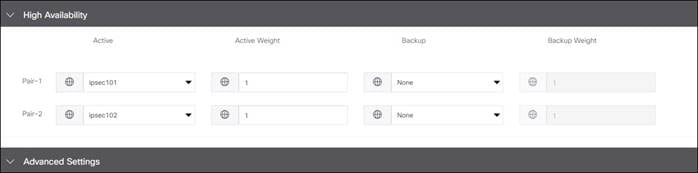
Step 15. Click Save to save the new SIG feature template.
Procedure 5. Modify Device Template
Add the SIG feature template to the device template. This step assumes there is not a previous SIG feature template configuration already defined. If there is a previous SIG feature template configuration already defined, it is recommended to delete it from the device template and push the config changes to the router before adding the new tunnel configuration.
Step 1. Go to Configuration>Templates. Under the Device Templates tab, next to the device template you want to modify, click … on the right-hand side, and select Edit from the drop-down menu.
Step 2. Under Transport & Management VPN, click Cisco Secure Internet Gateway on the right-side under Additional Cisco VPN 0 Templates.
Step 3. Choose the new SIG template created in the last procedure (xeSig_Zscaler_2_Loopback_Source).
Step 4. Click Cisco VPN Interface Ethernet on the right-hand side 2 times under VPN 0 and choose a Loopback 1-2 for each.
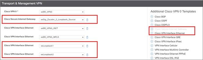
Step 5. Under Additional Templates, choose the CLI Add-On Template created earlier (CLI-Template).
Step 6. Before the device template can be saved, the SIG Credentials template needs to be attached. In SD-WAN Manager version 20.9 and above, this is done automatically when a SIG feature template is attached to the device template. If running a lower SD-WAN Manager version, next to Cisco SIG Credentials *, attach the SIG credentials feature template that was built in the pre-requisites section.
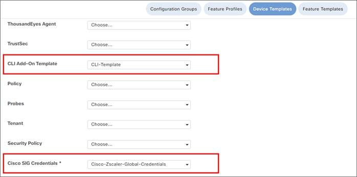
Step 7. Click Update.
Step 8. Next to the device you need to define values for, click … and select Edit Device Template.
Step 9. Fill in values for the variables created in the feature template attached.
Step 10. Click Update.
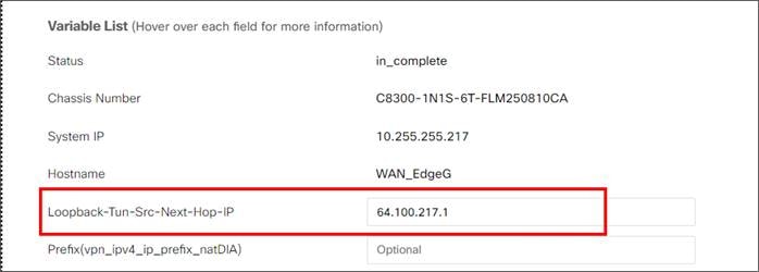
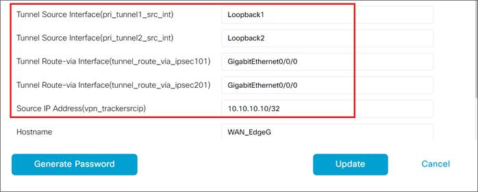
Step 11. Click Next, then Configure Devices. After the configuration changes are pushed to the WAN Edge, the status shows up as Success.
Step 12. Verify tunnel operation.
Procedure 6. Add Centralized Data Policy for Traffic Redirection
This section assumes a centralized policy already exists in the network and is activated on the SD-WAN Controllers. An example data policy is constructed which directs:
● Company destination traffic to take the SD-WAN overlay tunnels
● DNS requests to use the Internet transport directly (DIA) (if the Internet transport fails, traffic is routed over the overlay)
● Box application traffic to use the Internet transport directly (DIA) (if the Internet transport fails, traffic is routed over the overlay)
● The remaining traffic over the SIG tunnels.
Step 1. Go to Configuration>Policies and under Custom Options, select Lists under Centralized Policy.
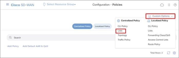
Step 2. Select Data Prefix on the left-hand side and create a Prefix List called Overlay that contains the 10.0.0.0/8 prefix and any other site prefix/summary advertised into the SD-WAN overlay.
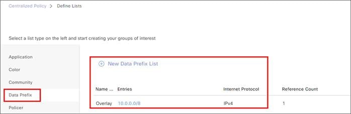
Step 3. Select Application on the left-hand side and create a New Application List called Box.
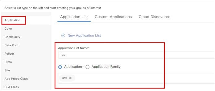
Step 4. Ensure the WAN Edge router you are applying the policy to is defined in a site list and there is a VPN list which contains the VPN you want to apply the policy to. If not, create the site list.
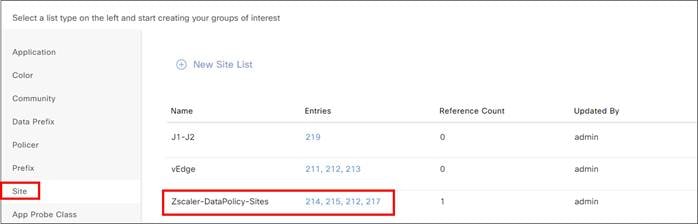
Step 5. The service VPN for Zscaler traffic is VPN 1. Create the VPN list if needed.
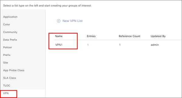
Step 6. To edit or create a new traffic policy for a WAN Edge router, go to Custom Options and under Centralized Policy, select Traffic Policy.
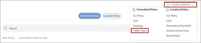
Step 7. Click the Traffic Data tab at the top of the page.
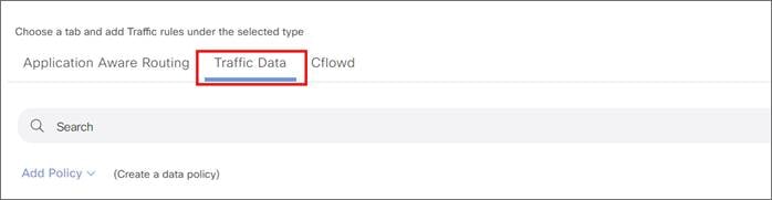
Step 8. If there is already a data policy attached to the WAN Edge router site you wish to add SIG data policy to, choose to edit the existing policy, else create a new data policy and import it into the master policy already attached to the SD-WAN Controllers. In this example, a new data policy is created and imported into a master policy already attached to the SD-WAN Controllers.
Step 9. Click Add Policy and select Create New from the drop-down menu.
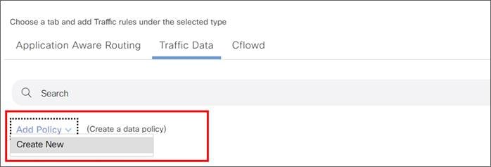
Step 10. Name the Data Policy (Sig_Data) and give it a Description (Data Policy for Sig Data).
Step 11. Click Sequence Type and select Custom.
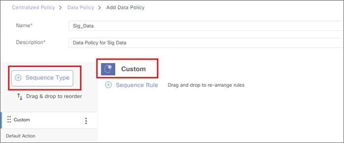
Step 12. Click Sequence Rule. Select Match Conditions and Actions, then click Save Match and Actions. Repeat as needed to complete the policy.
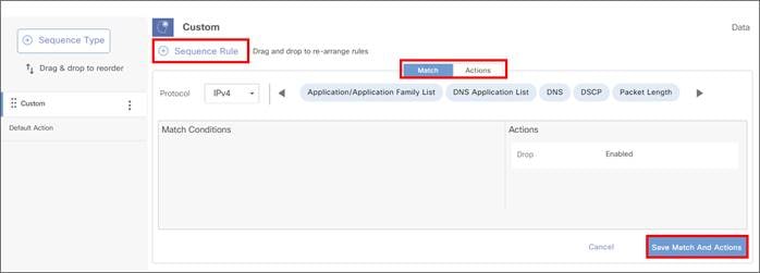
In this example, the following policy is configured:
| Sequence Rule |
Match Parameter |
Match Value |
Action/s |
| 1 |
Destination Data Prefix |
Overlay |
Accept |
| 2 |
DNS |
Request |
Accept/NAT VPN with Fallback |
| 3 |
Application/Application Family List |
Box |
Accept/NAT VPN with Fallback |
| 4 |
<empty> |
|
Accept/Secure Internet Gateway with Fallback |
Step 13. (optional) Change Default Action from Drop to Accept for your policy if necessary (not required for this policy).
| Tech tip |
| In earlier versions of IOS XE SD-WAN code and all versions of vEdge code, there is no fallback support for policy, meaning if all the SIG tunnels go down on the router, the data policy still forwards traffic to the SIG service, resulting in blackholing of traffic. If you are running earlier versions of code, you can redesign the policy so SIG traffic is routed normally by using an Accept action and then configure a SIG service route in the service VPN so SIG traffic is directed to the SIG tunnel, which does support fallback routing. If the SIG tunnels fail, the SIG service route is removed so traffic can follow routes in the SD-WAN overlay. Fallback routing for centralized data policy directing traffic to SIG is supported starting in 20.8.1 SD-WAN Manager/17.8.1 IOS XE SD-WAN versions of code. |
Step 14. Click Save Data Policy.
Step 15. Now this new data policy can be imported into the master policy already attached to the SD-WAN Controllers. In the SD-WAN Manager GUI, go to Configuration>Policies. Ensure Centralized Policy is selected. Choose to Edit the master policy (Central_Policy) that is currently activated.
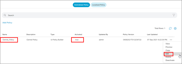
Step 16. Click Traffic Rules at the top of the page so the new data policy can be imported into the master policy. Click the Traffic Data tab. Click Add Policy and choose Import Existing from the drop-down menu.
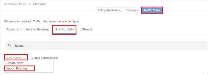
Step 17. In the popup window, select the policy name created and click Import.
Step 18. Once the policy is imported, it needs to be applied to a site list and VPN list. Click Policy Application at the top of the page. Click the Traffic Data tab. Under Sig_Data, click New Site List and VPN List.
Step 19. Ensure the radio button From Service is chosen so data policy is applied to traffic coming from the service VPN. Select Site list (Zscaler-DataPolicy-Sites) and VPN List (VPN1). Click Add, then Save Policy Changes.
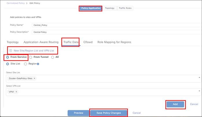
Step 20. A popup window appears so update policy can be pushed to the SD-WAN Controllers. Click Activate.
Procedure 7. (optional) Assign Tunnel Weights
In this section, different tunnel weights are assigned to the active tunnels.
Step 1. In the SD-WAN Manager GUI, go to Configuration>Templates and click the Feature Templates tab. To the right of the SIG template that was created in the earlier section (xeSig_Zcaler_2_Loopback_Source), click … and select Edit from the drop-down menu.
Step 2. Under the High Availability section, configure the Active Weight column for each active tunnel.
| Section |
Parameter |
Type |
Variable/value |
| High Availability/Pair-1 |
Active |
Global |
ipsec101 |
|
|
Active Weight |
Global |
80 |
| High Availability/Pair-2 |
Active |
Global |
Ipsec102 |
|
|
Active Weight |
Global |
20 |
Step 3. Click Update to save changes to the SIG feature template.
Step 4. Click Next, then Configure Devices. You may need to confirm configuration changes on multiple devices. Click the checkbox and click OK. The configuration changes are pushed out to the attached WAN Edge routers.
The following shows different ways to monitor the Zscaler tunnels.
Verify Cisco Catalyst SD-WAN Tunnel Operation from the SD-WAN Manager GUI
Step 1. In the SD-WAN Manager GUI under Monitor>Tunnels, click the SIG Tunnels tab to view the tunnel status and any events related to the SIG tunnel.
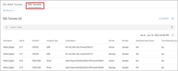
Step 2. In the SD-WAN Manager GUI under Monitor>Network, click the WAN Edge router that you want to verify the tunnel operation on.
Step 3. Under Applications>Interface, click Real Time at the top right of the chart. You can also click the interface you are interested in on the right-hand side of the chart.
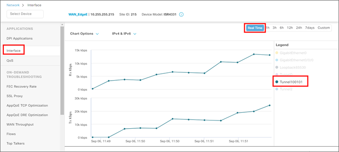
Step 4. If the interface you are interested in is missing from the graph, scroll down past the chart to see the entire list of interfaces. Click the checkbox on the left for the interface you want to display on the chart. You can also view the state and statistics of the various interfaces on the device from this list.
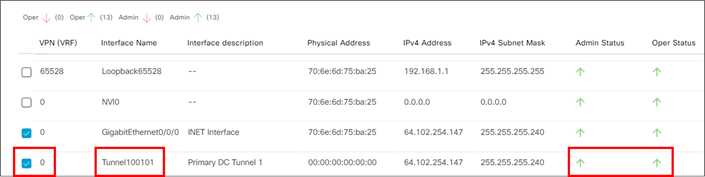
Verify Cisco Catalyst SD-WAN Event Logs from the SD-WAN Manager GUI
Step 1. In the SD-WAN Manager GUI, navigate to Monitor>Events.
Step 2. In the top right-hand corner, you can select the timeframe over which to see the events. The default is over the last 3 hours.
Step 3. In the Search bar, type in something to narrow down your search. In this example, all the WAN_EdgeB device events in the last 1 hour are being viewed.
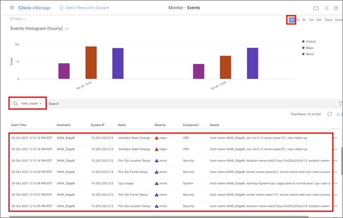
Events are generated when a location gets created, VPN credentials are associated with the tunnel, and when the tunnel state comes up.
Verify Zscaler Tunnel Status in ZIA Admin
If you want to check the current status of tunnels to ZIA from your sites, ZIA provides the ability to see the traffic volume sent / received from your SD-WAN appliances and logging to see the current state of the tunnels via logging.
In the ZIA GUI, navigate to Analytics>Insights>Tunnel Insights.
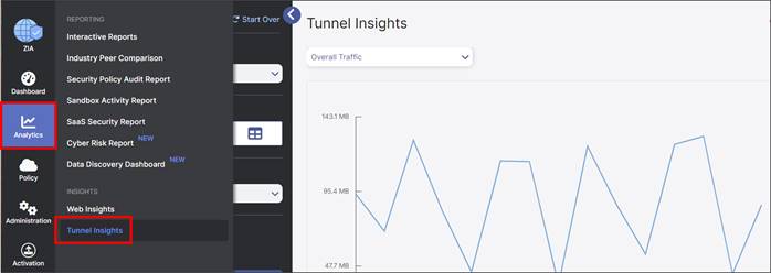
In the Insights screen, you have the ability to visualize and filter data in various ways. You can select how to categorize all tunnel traffic to graph from the drop-down menu under Tunnel Insights (by Overall Traffic, Location, Location Group, Location Type, Tunnel Destination IP, Tunnel Source IP, Tunnel Type, or by VPN Credential). You can also configure the Timeframe, ChartType, and Metrics you wish to view. Additionally, you can filter the data shown in the chart even further by clicking the Add Filter drop-down menu and selecting various filter types and values.
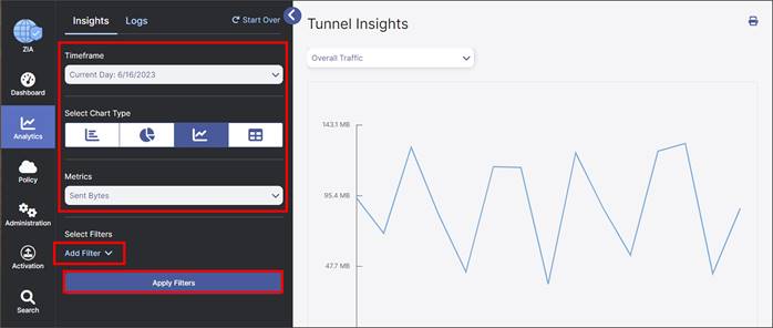
For further information, please refer to the ZIA Tunnel Insights help:
https://help.zscaler.com/zia/tunnel-data-tyes-and-filters.
Verify Zscaler Tunnel Event Logs in ZIA Admin
Tunnel Logging
To assist in troubleshooting, you can also view the state of all tunnels for your tenant from the ZIA Admin UI. Click on the Logs button. From this screen, you can then filter and change the timeframe for the tunnels and sites you would like to investigate.
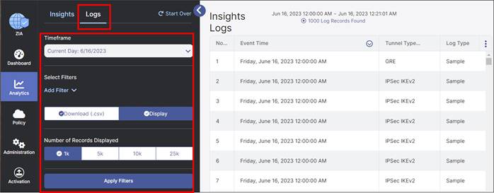
Please see the ZIA Tunnels Insights Logs: Columns help for details on the options:
https://help.zscaler.com/zia/tunnel-insights-logs-columns
View API Calls in Zscaler ZIA (Audit Logs)
Zscaler Internet Access provides the ability to view what changes are made to the tenant environment using the Audit Logging feature. This can also be used to view API calls into the platform.
Step 1. Navigate to Administration>Authentication>Audit Logs.
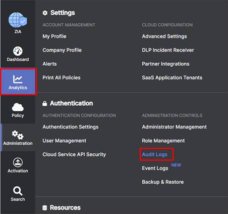
Step 2. In the Audit Logs window, you can filter out all changes to only view the API calls by selecting API under the Interface dropdown menu.
A list of all the API interactions will show, the Result column shows whether the call was successful or failed.
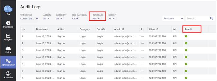
Verify Zscaler ZIA Service Configuration
The URL https://ip.zscaler.com from a host PC at a site can be used to validate if you are transiting ZIA. This is what you see if you are not transiting ZIA:
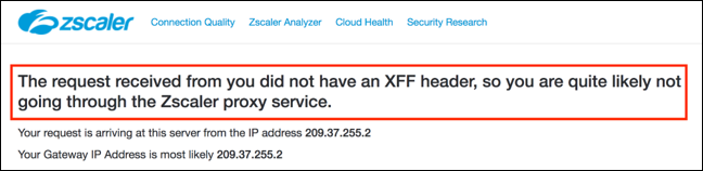
If you are transiting ZIA, you should see the following:
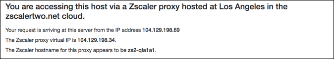
Verify Zscaler Tunnel Operation using IOS XE SD-WAN CLI
SSH to the WAN Edge router either directly or through the SD-WAN Manager GUI (Tools>SSH Terminal) and run the following command to verify the Zscaler tunnel operation using IOS XE SD-WAN CLI. Note that once the Zscaler API calls are successfully completed, IKEv2 and IPsec phase 2 can establish sessions. Once this completes successfully, L7 health checks can start running over the tunnels.
● show ip interface brief - shows interface state
● show sdwan secure-internet-gateway zscaler tunnels - shows ZIA tunnel information and last API state (applies only to automatic tunnels)
● show crypto ikev2 session – show crypto isakmp (v2) sessions
● show crypto ipsec sa – shows ipsec encryption/decryption statistics
● show ip route vrf <service vpn> - shows routing information for the service VPN
● show interface <tunnel> - shows traffic statistics
● show endpoint-tracker – shows L7 health tracker information
● show endpoint-tracker records - shows L7 health tracker information
● show ip sla statistics - shows L7 health tracker information
WAN_EdgeE#sh ip interface brief
Interface IP-Address OK? Method Status Protocol
GigabitEthernet0/0/0 64.100.215.2 YES other up up
GigabitEthernet0/0/1 10.215.10.1 YES other up up
GigabitEthernet0/0/2 192.168.215.2 YES other up up
Service-Engine0/4/0 unassigned YES unset up up
GigabitEthernet0 192.168.255.135 YES other up up
Sdwan-system-intf 10.255.255.215 YES unset up up
Loopback65528 192.168.1.1 YES other up up
Loopback65530 10.11.11.1 YES other up up
NVI0 unassigned YES unset up up
Tunnel0 64.100.215.2 YES TFTP up up
Tunnel2 192.168.215.2 YES TFTP up up
Tunnel100101 64.100.215.2 YES TFTP up up
Tunnel100201 64.100.215.2 YES TFTP up up
WAN_EdgeE#show sdwan secure-internet-gateway zscaler tunnels
-----------------------------------------------------------------------------------------
Tunnel100101 site215sys10x255x255x215ifTunnel100101 30556720 <removed> add-vpn-credential-info 30558350 location-init-state get-data-centers 200
Tunnel100201 site215sys10x255x255x215ifTunnel100201 30556721 <removed> add-vpn-credential-info 30558350 location-init-state get-data-centers 200
WAN_EdgeG#show sdwan secure-internet-gateway zscaler tunnels
----------------------------------------------------------------------------------------------
Tunnel100612 64.102.254.146_Tunnel100612 138705 n/a gre-add-tunnel 16351385 location-init-state activate-req 200
Tunnel100712 64.102.254.146_Tunnel100712 138705 n/a gre-add-tunnel 16351385 location-init-state activate-req 200
WAN_EdgeE#show crypto ikev2 session
IPv4 Crypto IKEv2 Session
Session-id:6, Status:UP-ACTIVE, IKE count:1, CHILD count:1
Tunnel-id Local Remote fvrf/ivrf Status
2 64.102.254.147/500 104.129.206.161/500 none/none READY
Encr:AES-CBC, keysize:256, PRF:SHA256, Hash:SHA256, DH Grp:14, Auth sign:PSK, Auth verify:PSK
Life/Active Time: 86400/949 sec
Child sa: local selector 0.0.0.0/0 - 255.255.255.255/65535
remote selector 0.0.0.0/0 - 255.255.255.255/65535
ESP spi in/out: 0x99AD50D4/0x3F86E386
Session-id:5, Status:UP-ACTIVE, IKE count:1, CHILD count:1
Tunnel-id Local Remote fvrf/ivrf Status
1 64.102.254.147/500 165.225.8.35/500 none/none READY
Encr:AES-CBC, keysize:256, PRF:SHA256, Hash:SHA256, DH Grp:14, Auth sign:PSK, Auth verify:PSK
Life/Active Time: 86400/949 sec
Child sa: local selector 0.0.0.0/0 - 255.255.255.255/65535
remote selector 0.0.0.0/0 - 255.255.255.255/65535
ESP spi in/out: 0x75ABF7D3/0x25E5276B
WAN_EdgeE#show crypto ipsec sa
interface: Tunnel0
Crypto map tag: Tunnel0-vesen-head-0, local addr 64.102.254.147
protected vrf: (none)
local ident (addr/mask/prot/port): (64.102.254.147/255.255.255.255/0/12387)
remote ident (addr/mask/prot/port): (64.102.254.146/255.255.255.255/0/12426)
current_peer 64.102.254.146 port 12426
PERMIT, flags={origin_is_acl,}
#pkts encaps: 32144, #pkts encrypt: 32144, #pkts digest: 32144
#pkts decaps: 32144, #pkts decrypt: 32144, #pkts verify: 32144
WAN_EdgeE#show ip route vrf 1
…
Gateway of last resort is 0.0.0.0 to network 0.0.0.0
S* 0.0.0.0/0 [2/65535], Tunnel100101
10.0.0.0/8 is variably subnetted, 26 subnets, 3 masks
m 10.4.0.0/30 [251/0] via 10.255.255.202, 2d03h, Sdwan-system-intf
[251/0] via 10.255.255.201, 2d03h, Sdwan-system-intf
m 10.4.0.4/30 [251/0] via 10.255.255.202, 2d03h, Sdwan-system-intf
[251/0] via 10.255.255.201, 2d03h, Sdwan-system-intf
m 10.4.0.8/30 [251/0] via 10.255.255.202, 2d03h, Sdwan-system-intf
[251/0] via 10.255.255.201, 2d03h, Sdwan-system-intf
WAN_EdgeE#sh interface Tunnel100101
Tunnel100101 is up, line protocol is up
Hardware is Tunnel
Description: Primary DC Tunnel 1
Interface is unnumbered. Using address of GigabitEthernet0/0/0 (64.100.215.2)
MTU 9950 bytes, BW 100 Kbit/sec, DLY 50000 usec,
reliability 255/255, txload 51/255, rxload 5/255
Encapsulation TUNNEL, loopback not set
Keepalive not set
Tunnel linestate evaluation up
Tunnel source 64.100.215.2 (GigabitEthernet0/0/0), destination 165.225.48.10
WAN_EdgeG#show interface Tunnel100612
Tunnel100612 is up, line protocol is up
Hardware is Tunnel
Interface is unnumbered. Using address of GigabitEthernet0/0/0 (64.102.254.146)
MTU 9976 bytes, BW 100 Kbit/sec, DLY 50000 usec,
reliability 255/255, txload 1/255, rxload 1/255
Encapsulation TUNNEL, loopback not set
Keepalive not set
Tunnel linestate evaluation up
Tunnel source 64.102.254.146 (GigabitEthernet0/0/0), destination 104.129.194.45
Tunnel Subblocks:
src-track:
Tunnel100612 source tracking subblock associated with GigabitEthernet0/0/0
Set of tunnels with source GigabitEthernet0/0/0, 3 members (includes iterators)
Tunnel protocol/transport GRE/IP
WAN_EdgeE#show endpoint-tracker
Interface Record Name Status RTT in msecs Probe ID Next Hop
Tunnel100101 #SIGL7#AUTO#TRACKER Up 10 5 None
Tunnel100201 #SIGL7#AUTO#TRACKER Up 11 6 None
WAN_EdgeE#show endpoint-tracker records
Record Name Endpoint EndPoint Type Threshold(ms) Multiplier Interval(s) Tracker-Type
#SIGL7#AUTO#TRACKER http://gateway.zscalerthree.net/vpn API_URL 1000 2 30 interface
WAN_EdgeE#show ip sla statistics
IPSLAs Latest Operation Statistics
IPSLA operation id: 11
Latest RTT: 32 milliseconds
Latest operation start time: 03:02:28 UTC Wed Nov 24 2021
Latest operation return code: OK
Latest DNS RTT: 10 ms
Latest TCP Connection RTT: 11 ms
Latest HTTP Transaction RTT: 11 ms
Number of successes: 69
Number of failures: 1
Operation time to live: Forever
IPSLA operation id: 12
Latest RTT: 37 milliseconds
Latest operation start time: 03:02:28 UTC Wed Nov 24 2021
Latest operation return code: OK
Latest DNS RTT: 11 ms
Latest TCP Connection RTT: 15 ms
Latest HTTP Transaction RTT: 11 ms
Number of successes: 69
Number of failures: 1
Operation time to live: Forever
Verify Zscaler Tunnel Operation using vEdge CLI
SSH to the WAN Edge router either directly or through the SD-WAN Manager GUI (Tools>SSH Terminal) and run the following command to verify the Zscaler tunnel operation using vEdge CLI. Note that once the Zscaler API calls are successfully completed, IKEv2 and IPsec phase 2 can establish sessions. Once this completes successfully, L7 health checks can start running over the tunnels.
● show interface | tab | in ipsec – shows tunnel state
● show secure-internet-gateway zscaler tunnels - shows ZIA tunnel information and last API state
● show ipsec ike sessions – shows crypto isakmp (v2) sessions
● show tunnel statistics ipsec – shows ipsec encryption/decryption statistics
● show ip route vpn <service vpn> - shows routing information for the service VPN
● show ip fib vpn <service vpn> - shows next hop information for the service VPN
● show ip nat filter or show ip nat filter | tab – shows active nat translations
● show interface statistics – shows traffic statistics for each interface
● show support tracker interface monitors – shows L7 health tracker information
WAN_EdgeB# show interface | tab | in ipsec
0 ipsec101 ipv4 - Up Up Up vlan service 1400 00:00:00:00:00:01 1000 full 1316 0:05:32:03 4002 2524
0 ipsec201 ipv4 - Up Up Up vlan service 1400 00:00:00:00:00:01 1000 full 1316 0:05:32:03 4009 2512
WAN_EdgeB# show secure-internet-gateway zscaler tunnels
zscaler tunnels ipsec101
tunnel-name site212sys10x255x255x212ifipsec101
tunnel-id 33685023
fqdn (REMOVED)
tunnel-fsm-state add-vpn-credential-info
location-id 33685046
location-fsm-state location-init-state
last-http-req get-data-centers
http-resp-code 200
zscaler tunnels ipsec201
tunnel-name site212sys10x255x255x212ifipsec201
tunnel-id 33685030
fqdn (REMOVED)
tunnel-fsm-state add-vpn-credential-info
location-id 33685046
location-fsm-state location-init-state
last-http-req get-data-centers
http-resp-code 200
WAN_EdgeB# show ipsec ike sessions
ipsec ike sessions 0 ipsec101
version 2
source-ip 64.100.212.2
source-port 4500
dest-ip 104.129.206.161
dest-port 4500
initiator-spi 11e994148c8c114c
responder-spi ba604f6bfa667181
cipher-suite aes256-cbc-sha1
dh-group "2 (MODP-1024)"
state IKE_UP_IPSEC_UP
uptime 0:02:17:35
tunnel-uptime 1:01:16:19
ipsec ike sessions 0 ipsec201
version 2
source-ip 64.100.212.2
source-port 4500
dest-ip 165.225.34.44
dest-port 4500
initiator-spi 0a977da74a8ca235
responder-spi dc36839e3b9138e4
cipher-suite aes256-cbc-sha1
dh-group "2 (MODP-1024)"
state IKE_UP_IPSEC_UP
uptime 0:02:15:45
tunnel-uptime 1:01:16:19
WAN_EdgeB# show tunnel statistics ipsec
IPSEC IPSEC RX IPSEC IPSEC TX
TUNNEL SOURCE DEST DECRYPT AUTH IPSEC RX ENCRYPT AUTH IPSEC TX
PROTOCOL SOURCE IP DEST IP PORT PORT IN FAIL FAIL OUT FAIL FAIL
------------------------------------------------------------------------------------------
ipsec 64.100.212.2 64.100.1.23 12346 10424 370572 1 0 370570 0 8
ipsec 64.100.212.2 64.100.1.24 12346 65008 370594 1 0 370593 0 7
ipsec 64.100.212.2 104.129.206.161 4500 4500 15168 0 0 18970 0 0
ipsec 64.100.212.2 165.225.34.44 4500 4500 15176 0 0 18977 0 0
WAN_EdgeB# show ip route vpn 1
PROTOCOL NEXTHOP NEXTHOP NEXTHOP
VPN PREFIX PROTOCOL SUB TYPE IF NAME ADDR VPN TLOC IP COLOR ENCAP STATUS
--------------------------------------------------------------------------------------------
1 0.0.0.0/0 std-ipsec - ipsec101 - 0 - - - F,S
1 0.0.0.0/0 omp - - - - 10.255.255.201 mpls ipsec -
WAN_EdgeB# show ip fib vpn 1
NEXTHOP NEXTHOP NEXTHOP NEXTHOP SA
VPN PREFIX IF NAME ADDR LABEL VPN INDEX TLOC IP COLOR
-----------------------------------------------------------------------------------------
1 0.0.0.0/0 ipsec 165.225.48.10 - - 34 - -
1 10.4.0.0/30 ipsec 10.4.1.2 1003 - 7 10.255.255.201 mpls
1 10.4.0.0/30 ipsec 64.100.1.23 1003 - 28 10.255.255.201 biz-internet
WAN_EdgeB# show ip nat filter (or show ip nat filter | tab)
ip nat filter nat-vpn 0 nat-ifname ge0/0 vpn 0 protocol udp 64.100.212.2 64.102.254.147
public-source-address 64.100.212.2
public-dest-address 64.102.254.147
public-source-port 12346
public-dest-port 12367
filter-state established
idle-timeout 0:00:00:59
outbound-packets 3296
outbound-octets 519226
inbound-packets 3294
inbound-octets 593424
ip nat filter nat-vpn 0 nat-ifname ge0/2 vpn 0 protocol udp 10.10.10.1 104.129.206.161
public-source-address 192.168.212.2
public-dest-address 104.129.206.161
public-source-port 4500
public-dest-port 4500
filter-state established
idle-timeout 0:00:00:52
outbound-packets 15105
outbound-octets 1851428
inbound-packets 15077
inbound-octets 1846978
WAN_EdgeB# show interface statistics
AF RX RX RX RX TX TX TX TX RX RX TX TX
VPN INTERFACE TYPE PACKETS OCTETS ERRORS DROPS PACKETS OCTETS ERRORS DROPS PPS Kbps PPS Kbps
0 ge0/0 ipv4 423562 70604112 0 213 437205 74796702 0 0 17 22 17 23
0 ipsec101 ipv4 4333 536138 0 0 2731 340154 0 0 0 0 0 0
0 ipsec201 ipv4 4336 536532 0 0 2717 337982 0 0 0 0 0 0
WAN_EdgeB# show support tracker interface monitors
Interface: ipsec101/#SIGL7#AUTO#TRA#ZIA
Monitor: 65530/http://gateway.zscalerthree.net/vpntest/80 via ipsec101
Monitor state : UP (flapped 0 times)
Ref count : 1
Monitor type : httping
Probe / DNS SIP : 192.168.0.2 / ::
Nameserver IP : 208.67.222.222
Src Port Base : 49172
Num of probes : 1
Max Re-transmit : 2
First Probe : 0 secs
Probe interval : 30 secs
Probe timeout : 1000 msecs
DNS TTL : 96 secs
DNS query/ok/fail : 611/611/0
Peer: 165.225.48.11 (UP - flapped 0 times, nretries 0)
Total requests : 0 Total responses : 0
Total Tx errors : 0 Total Rx errors : 0
Total Tx skipped: 0 Total Rx ignored: 0
Total timeout : 0 Connect errors : 0
RTT min/avg/max : 0.00/0.00/0.00 ms
Conn min/avg/max: 0.00/0.00/0.00 ms
Interface: ipsec201/#SIGL7#AUTO#TRA#ZIA
Monitor: 65530/http://gateway.zscalerthree.net/vpntest/80 via ipsec201
Monitor state : UP (flapped 0 times)
Ref count : 1
Monitor type : httping
Probe / DNS SIP : 192.168.0.2 / ::
Nameserver IP : 208.67.222.222
Src Port Base : 49173
Num of probes : 1
Max Re-transmit : 2
First Probe : 0 secs
Probe interval : 30 secs
Probe timeout : 1000 msecs
DNS TTL : 96 secs
DNS query/ok/fail : 611/611/0
Peer: 165.225.48.11 (UP - flapped 0 times, nretries 0)
Total requests : 0 Total responses : 0
Total Tx errors : 0 Total Rx errors : 0
Total Tx skipped: 0 Total Rx ignored: 0
Total timeout : 0 Connect errors : 0
RTT min/avg/max : 0.00/0.00/0.00 ms
Conn min/avg/max: 0.00/0.00/0.00 ms
Appendix A: Document Revision Control
| Revision |
Date |
Change Log |
| 1.0 |
August 2017 |
Initial document by Zscaler and Viptela |
| 1.1 |
August 2017 |
Updated Viptela references to Cisco SD-WAN |
| 1.2 |
September 2017 |
Minor edits |
| 1.3 |
September 2018 |
Updated ZIA screen captures to ZIA 5.6 and added IPsec section and other supporting edits |
| 2.0 |
March 2019 |
Added GRE and IPsec template creation |
| 3.0 |
January 2020 |
Cisco SD-WAN: Updated for 19.2.099 and 19.3.0 vManage code, added IOS XE SD-WAN router information, added design information, added L7 health checking, and tested the ISR1100-4G running vEdge code. |
| 3.1 |
February 2020 |
Incorporated review feedback |
| 4.0 |
November 2021 |
Cisco SD-WAN: Updated for 20.6 vManage and vEdge code and 17.6 IOS XE SD-WAN Edge code, added new information on vManage SIG templates, IPsec auto tunnels (active/standby and active/active tunnels), SIG service routes, and data policy. |
| 5.0 |
May 2023 |
Cisco SD-WAN: Updated for 20.9 vManage and vEdge code and 17.9 IOS XE SD-WAN Edge code, added new information on GRE auto tunnels, Cisco SD-WAN and Zscaler design, and other features supported since 20.6 vManage/17.6 IOS XE SD-WAN code versions. Due to product rebranding, updated Cisco SD-WAN references to Cisco Catalyst SD-WAN, and updated vManage, vSmart, and vBond references to SD-WAN Manager, Controller, and Validator. |
Appendix B: Terms and Acronyms
The following terms and acronyms may be used in this guide:
| Acronymn/Term |
Definition |
| DPD |
Dead Peer Detection (RFC 3706) |
| DTLS |
Datagram Transport Layer Security (RFC6347) |
| GRE |
Generic Routing Encapsulation (RFC2890) |
| IKE |
Internet Key Exchange (RFC2409) |
| IPsec |
Internet Protocol Security (RFC2411) |
| OAM |
Operation, Administration, and Management |
| OMP |
Overlay Management Protocol (Cisco Catalyst SD-WAN) |
| PFS |
Perfect Forward Secrecy |
| SSL |
Secure Socket Layer (RFC6101) |
| TLS |
Secure Socket Layer Transport Layer Security (RFC5246) |
| SD-WAN Validator |
Cisco Catalyst SD-WAN component which facilitates the initial bring-up authentication and authorization of the network elements. Formerly referred to as vBond. |
| SD-WAN Manager |
Cisco Catalyst SD-WAN centralized network management system that provides a GUI interface and REST APIs to monitor, configure, and maintain all Cisco Catalyst SD-WAN devices in the overlay network. Formerly referred to as vManage. |
| SD-WAN Controller |
Cisco Catalyst SD-WAN centralized control plane and policy engine. Formerly referred to as vSmart. |
| WAN Edge |
Cisco Catalyst SD-WAN Router Platform |
| XFF |
X-Forwarded-For (RFC7239) |
| ZAPP |
Zscaler End-point Client Application |
| ZIA |
Zscaler Internet Access (Zscaler) |
| ZPA |
Zscaler Private Access (Zscaler) |
Appendix C: Validated Hardware and Software
The following products and software versions are included as part of validation in this deployment guide. This validated set is not inclusive of all possibilities.
| Product/Part Number |
Software version |
| Zscaler ZIA |
6.2 |
| SD-WAN Manager |
20.9.3.1 |
| ISR4331 |
17.9.3 |
| C8300-1N1S-6T |
17.9.3 |
| ISR1100-4G (Viptela OS) |
20.9.3 |
| vEdge 100b |
20.6.5.3 |
Zscaler: Getting Started
https://help.zscaler.com/zia/getting-started
Zscaler Knowledge Base:
https://support.zscaler.com/hc/en-us/?filter=documentation
Zscaler Tools:
https://www.zscaler.com/tools
Zscaler Training and Certification:
https://www.zscaler.com/resources/training-certification-overview
Zscaler Submit a Ticket:
https://help.zscaler.com/submit-ticket
ZIA Test Page
http://ip.zscaler.com/
ZIA IP and VPN host name information by data center:
https://config.zscaler.com (then choose the cloud name from the drop-down).
or
Data centers by cloud:
https://config.zscaler.com/zscaler.net/cenr/
https://config.zscaler.com/zscalerbeta.net/cenr/
https://config.zscaler.com/zscalerone.net/cenr/
https://config.zscaler.com/zscalertwo.net/cenr/
https://config.zscaler.com/zscalerthree.net/cenr/
https://config.zscaler.com/zscloud.net/cenr
https://config.zscaler.com/zscalergov.net/cenr
Appendix E: Requesting Zscaler Support
Zscaler support is sometimes required for the provisioning of certain services. Zscaler support is also available to help troubleshoot configuration and service issues. Zscaler support is available 24/7 hours a day, year-round.
Procedure 1. Obtain Company ID
Before opening a support ticket, obtaining the company is necessary, which is how Zscaler uniquely identifies a given customer.
Step 1. On the ZIA GUI, navigate to Administration>Settings>Company Profile.
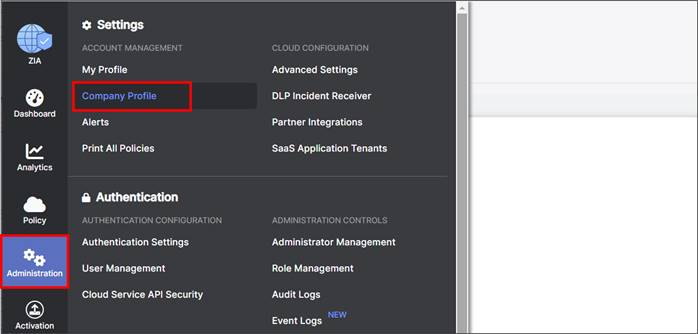
Step 2. Your Company ID is found in the red box below. Copy this ID somewhere convenient as it is needed in subsequent screens.
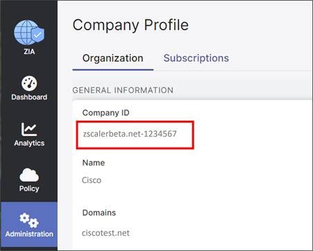
Procedure 2. Open a Support Ticket
Step 1. From the ZIA GUI, navigate to ?>Support>Submit a Ticket. You can also go directly to the ZIA - Submit Ticket page by visiting https://help.zscaler.com/submit-ticket.
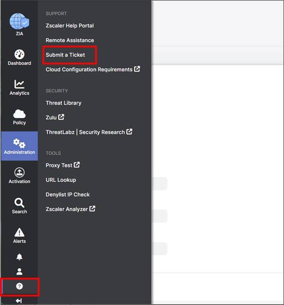
The following shows an example of how a support ticket is generally made. Each support ticket asks targeted questions as a Ticket Type is defined. In the example below, a domain is requested to be added to the ZIA instance.
Step 2. Fill in the required fields, then click Submit.
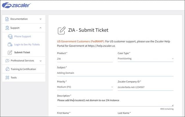
Appendix F: Cisco Catalyst SD-WAN Resources
For an overview on the Cisco Catalyst SD-WAN solution, see the Cisco Catalyst SD-WAN Design Guide at https://www.cisco.com/c/en/us/td/docs/solutions/CVD/SDWAN/cisco-sdwan-design-guide.html
For additional information on deploying a Cisco Catalyst SD-WAN network from end to end, see the Cisco Catalyst SD-WAN End-to-End Deployment Guide at https://www.cisco.com/c/dam/en/us/td/docs/solutions/CVD/SDWAN/SD-WAN-End-to-End-Deployment-Guide.pdf
For all Cisco EN Validated Design and Deployment guides, go to http://cs.co/en-cvds.
For the Cisco Catalyst SD-WAN Communities resource page and discussion board, see http://cs.co/sdwan-resources.
For additional Cisco Catalyst SD-WAN resources, including training opportunities and opening support cases, go to https://www.cisco.com/go/sd-wan.
Appendix G: Cisco Branch Base Feature Templates and Configuration Values Used
This appendix shows the branch non-default base device and feature template configurations used and referenced in this guide. Zscaler tunnel configurations in the main body of this paper are built on top of these configurations. If you need step-by-step instructions on configuring device and feature templates, refer to the Cisco End-to-End Deployment Guide.
Feature Templates
Note that these branch base configuration feature templates can be applied to vEdge or IOS XE SD-WAN routers, however, when you define them, they must be defined for vEdge devices or IOS XE SD-WAN devices and not both. At the time of this writing, from SD-WAN Manager version 20.1 and higher, feature templates cannot apply to both vEdge and IOS XE SD-WAN devices – they must have separate feature templates. Each template name below is preceded by either v or vEdge_ if the device type is a vEdge device, or an xe or xeEdge_ if the device type is an IOS XE SD-WAN device.
When creating feature templates for vEdge routers, if you want to cover the most models possible when selecting devices, choose all ISR 1100 models with Viptela OS, and all vEdge devices (all vEdge 100 types, vEdge 1000, vEdge 2000, vEdge 5000, and vEdge Cloud).
When creating feature templates for IOS XE SD-WAN routers, if you want to cover the most models possible when selecting devices, choose all models except the ISR 1100 models with Viptela OS, all vEdge devices, CG (Cellular Gateway) devices, vManage, and vSmart devices. When creating SIG feature templates, you must also exclude the IR8140s and IR8340 from the device model list.
AAA feature template (IOS XE SD-WAN)
Template: Basic Information/Cisco AAA
Template Name: xeAAA
Description: AAA Template for WAN Edge Routers
| Section |
Parameter |
Type |
Variable/value |
| Local |
Username |
Global |
netadmin |
|
|
Password |
Global |
(hidden) |
|
|
Privilege Level |
Global |
15 |
AAA feature template (vEdge)
Template: Basic Information/AAA
Template Name: vAAA
Description: AAA Template for WAN Edge Routers
| Section |
Parameter |
Type |
Variable/value |
| Local/New User |
Name |
Global |
netadmin |
|
|
Password |
Global |
(hidden) |
|
|
User Groups |
Global |
netadmin |
NTP Feature Template
Template: Basic Information/Cisco NTP
Template Name: NTP
Description: NTP Template for WAN Edge Routers
| Section |
Parameter |
Type |
Variable/value |
| Server |
Hostname/IP address |
Global |
time.google.com |
|
|
Source Interface |
Device Specific |
ntp_server_source_int |
Branch VPN0 Feature Template
Template: VPN/VPN
Template Name: BR_VPN0
Description: VPN 0 Template for WAN Edge Branch Routers
| Section |
Parameter |
Type |
Variable/value |
| Basic Configuration |
VPN |
Global |
0 |
|
|
Name |
Global |
Transport VPN |
|
|
Enhance ECMP Keying |
Global |
On |
| Primary DNS Address |
Global |
208.67.222.222 |
|
|
|
Secondary DNS Address |
Global |
208.67.220.220 |
|
|
Hostname |
Global |
vbond.cisco.net |
|
|
List of IP Addresses |
Global |
64.100.100.113 |
| IPv4 Route |
Prefix |
Global |
0.0.0.0/0 |
|
|
Gateway |
Radio Button |
Next Hop |
|
|
Next Hop |
Device Specific |
vpn0_next_hop_ip_addr_inet |
|
|
Next Hop |
Device Specific |
vpn0_next_hop_ip_addr_mpls |
Branch Internet Interface Feature Template (IOS XE SD-WAN)
Template: VPN/VPN Interface Ethernet
Template Name: xeBR_VPN0_INET
Description: VPN 0 INET Interface Template for WAN Edge Branch Routers
| Section |
Parameter |
Type |
Variable/value |
| Basic Configuration |
Shutdown |
Device Specific |
vpn0_inet_shutdown |
|
|
Interface Name |
Device Specific |
vpn0_inet_int_name |
|
|
Description |
Global |
INET Interface |
| IPv4 Configuration |
IPv4 Address |
Radio Button |
Static |
|
|
IPv4 Address |
Device Specific |
vpn0_inet_ipv4_addr |
| Tunnel |
Tunnel Interface |
Global |
On |
|
|
Color |
Global |
biz-internet |
| Tunnel>Allow Service |
NTP |
Global |
On |
| NAT |
NAT |
Global |
On |
|
|
NAT Type |
Global |
Interface |
Branch Internet Interface Feature Template (vEdge)
Template: VPN/VPN Interface Ethernet
Template Name: vBR_VPN0_INET
Description: VPN 0 INET Interface Template for WAN Edge Branch Routers
| Section |
Parameter |
Type |
Variable/value |
| Basic Configuration |
Shutdown |
Device Specific |
vpn0_inet_shutdown |
|
|
Interface Name |
Device Specific |
vpn0_inet_int_name |
|
|
Description |
Global |
INET Interface |
| IPv4 Configuration |
IPv4 Address |
Radio Button |
Static |
|
|
IPv4 Address |
Device Specific |
vpn0_inet_ipv4_addr |
| Tunnel |
Tunnel Interface |
Global |
On |
|
|
Color |
Global |
biz-internet |
| Tunnel>Allow Service |
NTP |
Global |
On |
| NAT |
NAT |
Global |
On |
Branch MPLS Interface Feature Template
Template: VPN/VPN Interface Ethernet
Template Name: BR_VPN0_MPLS
Description: VPN 0 MPLS Interface Template for WAN Edge Branch Routers
| Section |
Parameter |
Type |
Variable/value |
| Basic Configuration |
Shutdown |
Device Specific |
vpn0_mpls_shutdown |
|
|
Interface Name |
Device Specific |
vpn0_mpls_int_name |
|
|
Description |
Global |
MPLS Interface |
| IPv4 Configuration |
IPv4 Address |
Radio Button |
Static |
|
|
IPv4 Address |
Device Specific |
vpn0_mpls_ipv4_addr |
| Tunnel |
Tunnel Interface |
Global |
On |
|
|
Color |
Global |
mpls |
|
|
Restrict |
Global |
On |
| Allow Service |
NTP |
Global |
On |
Branch VPN512 Interface Feature Template
Template: VPN/VPN Interface Ethernet
Template Name: VPN512_MGT_INT
Description: VPN 512 Management Interface Template for WAN Edge Routers
| Section |
Parameter |
Type |
Variable/value |
| Basic Configuration |
Shutdown |
Global |
No |
|
|
Interface Name |
Device Specific |
vpn512_int_name |
|
|
Description |
Global |
MGT Interface |
| IPv4 Configuration |
IPv4 Address |
Radio Button |
Static |
|
|
IPv4 Address |
Device Specific |
vpn512_int_ipv4_addr |
Branch VPN 1 Feature Template
Template: VPN/VPN
Template Name: BR_VPN1
Description: VPN 1 Template for the WAN Edge Branch Routers
| Section |
Parameter |
Type |
Variable/value |
| Basic Configuration |
VPN |
Global |
1 |
|
|
Name |
Global |
LAN |
Branch VPN1 Interface Feature Template
Template: VPN/VPN Interface Ethernet
Template Name: BR_VPN1_LAN_INT1
Description: VPN 1 LAN Interface Template for WAN Edge Branch Routers
| Section |
Parameter |
Type |
Variable/value |
| Basic Configuration |
Shutdown |
Device Specific |
vpn1_int1_shutdown |
|
|
Interface Name |
Device Specific |
vpn1_int1_name |
|
|
Description |
Device Specific |
vpn1_int1_description |
| IPv4 Configuration |
IPv4 Address |
Radio Button |
Static |
|
|
IPv4 Address |
Device Specific |
vpn1_int1_ipv4_addr |
Device Templates
The following device templates are used in this guide. The table indicates what non-default feature template is being used.
Single WAN Edge Router Sites (IOS XE SD-WAN)
Device Model: ISR4331 [E], C8300-1N1S-6T [G]
Template Name: xeEdge_Remote_[E,G]
Description: WAN Edge router remote site [E,G]
| Template type |
Template subtype |
Template name |
| Basic Information |
Cisco NTP |
xeNTP |
|
|
Cisco AAA |
xeAAA |
| VPN 0 |
Cisco VPN |
xeBR_VPN0 |
|
|
Cisco VPN Interface |
xeBR_VPN0_INET |
|
|
Cisco VPN Interface |
xeBR_VPN0_MPLS |
| VPN 512 |
Cisco VPN Interface |
xeVPN512_MGT_INT |
| VPN 1 |
Cisco VPN1 |
xeBR_VPN1 |
|
|
Cisco VPN Interface |
xeBR_VPN1_LAN_INT1 |
Single WAN Edge Router Sites (vEdge)
Device Model: vEdge-100b [A], ISR1100-4G [B]
Template Name: vEdge_Remote_[A,B]
Description: WAN Edge router remote site [A,B]
| Template type |
Template subtype |
Template name |
| Basic Information |
Cisco NTP |
vNTP |
|
|
Cisco AAA |
vAAA |
| VPN 0 |
VPN |
vBR_VPN0 |
|
|
VPN Interface |
vBR_VPN0_INET |
|
|
VPN Interface |
vBR_VPN0_MPLS |
| VPN 512 |
VPN Interface |
vVPN512_MGT_INT |
| VPN 1 |
VPN1 |
vBR_VPN1 |
|
|
VPN Interface |
vBR_VPN1_LAN_INT1 |
Device Variable Values
| Variable |
vEdge_RemoteA |
vEdge_RemoteB |
xeEdge_RemoteE |
xeEdge_RemoteG |
| Hostname |
WAN_EdgeA |
WAN_EdgeB |
WAN_EdgeE |
WAN_EdgeG |
| System IP |
10.255.255.211 |
10.255.255.212 |
10.255.255.215 |
10.255.255.217 |
| Site ID |
211 |
212 |
215 |
217 |
| Interface Name (vpn1_int1_name) |
ge0/0 |
ge0/3 |
GigabitEthernet0/0/0 |
GigabitEthernet0/0/0 |
| Description (vpn1_int1_description) |
LAN Interface |
LAN Interface |
LAN Interface |
LAN Interface |
| IPv4 Address (vpn1_int1_ipv4_addr) |
10.211.10.1/24 |
10.212.10.1/24 |
10.215.10.1/24 |
10.217.10.1/24 |
| Shutdown (vpn1_int1_shutdown) |
False |
False |
False |
False |
| Interface Name(vpn512_int_name) |
ge0/1 |
ge0/1 |
GigabitEthernet0 |
GigabitEthernet0 |
| IPv4 Address(vpn512_int_ipv4_addr) |
192.168.255.153/23 |
192.168.255.181/23 |
192.168.255.135/23 |
192.168.255.93/23 |
| Address(vpn0_next_hop_ip_addr_inet) |
64.102.254.151 |
64.100.212.1 |
64.102.254.151 |
64.100.217.1 |
| Address(vpn0_next_hop_ip_addr_mpls) |
192.168.211.1 |
192.168.212.1 |
192.168.215.1 |
192.168.217.1 |
| Interface Name(vpn0_mpls_int_name) |
ge0/2 |
ge0/2 |
GigabitEthernet0/0/2 |
GigabitEthernet0/0/2 |
| IPv4 Address(vpn0_mpls_ipv4_addr) |
192.168.211.2/30 |
192.168.212.2/30 |
192.168.215.2/30 |
192.168.217.2/30 |
| Shutdown (vpn0_mpls_shutdown) |
False |
False |
False |
False |
| Interface Name(vpn0_inet_int_name) |
ge0/4 |
ge0/0 |
GigabitEthernet0/0/0 |
GigabitEthernet0/0/0 |
| IPv4 Address(vpn0_inet_ipv4_addr) |
64.102.254.146/28 |
64.100.212.2/28 |
64.102.254.147/28 |
64.100.217.2/28 |
| Shutdown (vpn0_inet_shutdown) |
False |
False |
False |
False |
| Source Interface (ntp_server_source_int) |
ge0/4 |
ge0/0 |
GigabitEthernet0/0/0 |
GigabitEthernet0/0/0 |
Appendix H: Tunnel Configuration Summary (Feature and Device Templates)
Prerequisites
● Verify that NAT is enabled on the Internet interface that is used to access Zscaler.
● Verify that a primary and/or secondary DNS server is defined in the VPN 0 feature template.
● Verify NTP is enabled, synced and the clock is correct.
Cisco VPN Interface Ethernet Feature Template
Template: VPN/VPN Interface Ethernet
Template Name: xeBR_VPN0_INET
Description: VPN0 INET Interface Template for WAN Edge Branch Routers
| Section |
Parameter |
Type |
Variable/value |
| NAT |
NAT |
Global |
On |
|
|
NAT Type |
Global |
Interface |
Cisco VPN Feature Template
Template: VPN/Cisco VPN
Template Name: xeBR_VPN0
Description: VPN0 Template for WAN Edge Branch Routers
| Section |
Parameter |
Type |
Variable/value |
| DNS |
Primary DNS Address (IPv4) |
Global |
208.67.222.222 |
|
|
Secondary DNS Address (IPv4) |
Global |
208.67.220.220 |
Cisco VPN Feature Template
Template: Basic Information/Cisco NTP
Template Name: xeNTP
Description: NTP Template for WAN Edge Branch Routers
| Section |
Parameter |
Type |
Variable/value |
| Server |
Hostname/IP address |
Global |
time.google.com |
|
|
Source Interface |
Device Specific |
ntp_server_source_int |
SIG Credential Information from ZIA
| SD-WAN Manager SIG Credentials Parameter |
Zscaler GUI Location |
Zscaler Parameter |
Zscaler Value |
| Organization |
Administration>Company Profile>Organization |
Domains |
ciscotest.net (example) |
| Partner Base URI |
Administration>Authentication>Cloud Service API Security>Cloud Service API Key |
Base URL for your API |
zsapi.zscalerbeta.net/api/v1 (example) |
| Administration>Administration Controls>Administrator Management>Administrators |
Partner Admin Login ID |
sd-wan@ciscotest.net (example) |
|
| Password |
Administration>Administration Controls>Administrator Management>Administrators |
Partner Admin Password |
(hidden) |
| Partner API Key |
Administration>Settings>Cloud Configuration>Partner Integrations>SD-WAN |
Partner Name (Cisco Viptela) Key |
ABCdef123GHI (example) |
Cisco SIG Credentials Feature Template
Template: Other Templates/Cisco SIG Credentials
Template Name: xeSig_Credentials
Description: IOS XE Sig Credentials Template
| Section |
Parameter |
Type |
Variable/value |
| Basic Details |
SIG Provider |
Radio Button |
Zscaler |
|
|
Organization |
Global |
ciscotest.net (example) |
|
|
Partner Base URI |
Global |
zsapi.zscalerbeta.net/api/v1 (example) |
|
|
Username |
Global |
sd-wan@ciscotest.net (example) |
|
|
Password |
Global |
(hidden) |
|
|
Partner API Key |
Global |
ABCdef123GHI (example) |
Example 1: Active/Standby Tunnels
● Create a Cisco Secure Internet Gateway (SIG) Feature Template (GRE or IPsec)
● Add Cisco Secure Internet Gateway (SIG) feature Template and SIG Credential feature template (if needed) to the Device Template
Cisco Secure Internet Gateway (SIG) Feature Template (GRE)
Template: VPN/Cisco Secure Internet Gateway (SIG)
Template Name: xeSig_Zscaler
Description: IOS XE Sig Zscaler Template
| Section |
Parameter |
Type |
Variable/value |
|
|
SIG Provider |
Radio Button |
Zscaler |
| Tracker (Beta) |
Source IP Address |
Device Specific |
vpn_trackersrcip |
| Configuration |
|
|
|
| Tunnel Name (gre101) |
Interface Name |
Global |
gre101 |
|
|
Description |
Global |
Primary DC Tunnel 1 |
|
|
Tunnel Source Interface |
Device Specific |
pri_tunnel1_src_int |
|
|
Data-Center |
Radio Button |
Primary |
|
|
Source Public IP |
Device Specific |
pri_tunnel1_src_public_ip |
| Tunnel Name (gre201) |
Interface Name |
Global |
ipsec201 |
|
|
Description |
Global |
Secondary DC Tunnel 1 |
|
|
Tunnel Source Interface |
Device Specific |
sec_tunnel1_src_int |
|
|
Data-Center |
Radio Button |
Secondary |
|
|
Source Public IP |
Device Specific |
sec_tunnel1_src_public_ip |
| High Availability/Pair-1 |
Active |
Global |
gre101 |
|
|
Backup |
Global |
gre201 |
Cisco Secure Internet Gateway (SIG) Feature Template (IPsec)
Template: VPN/Cisco Secure Internet Gateway (SIG)
Template Name: xeSig_Zscaler
Description: IOS XE Sig Zscaler Template
| Section |
Parameter |
Type |
Variable/value |
|
|
SIG Provider |
Radio Button |
Zscaler |
| Tracker (Beta) |
Source IP Address |
Device Specific |
vpn_trackersrcip |
| Tunnel Name (ipsec101) |
Interface Name |
Global |
ipsec101 |
|
|
Description |
Global |
Primary DC Tunnel 1 |
|
|
Tunnel Source Interface |
Device Specific |
pri_tunnel1_src_int |
|
|
Data-Center |
Radio Button |
Primary |
| Tunnel Name (ipsec201) |
Interface Name |
Global |
ipsec201 |
|
|
Description |
Global |
Secondary DC Tunnel 1 |
|
|
Tunnel Source Interface |
Device Specific |
sec_tunnel1_src_int |
|
|
Data-Center |
Radio Button |
Secondary |
| High Availability/Pair-1 |
Active |
Global |
ipsec101 |
|
|
Backup |
Global |
ipsec201 |
Device Template
| Template type |
Template subtype |
Template name |
| Basic Information |
Cisco NTP |
xeNTP |
|
|
Cisco AAA |
xeAAA |
| VPN 0 |
Cisco VPN |
xeBR_VPN0 |
|
|
Cisco Secure Internet Gateway |
xeSig_Zscaler |
|
|
Cisco VPN Interface |
xeBR_VPN0_INET |
|
|
Cisco VPN Interface |
xeBR_VPN0_MPLS |
| VPN 512 |
Cisco VPN Interface |
xeVPN512_MGT_INT |
| VPN 1 |
Cisco VPN1 |
xeBR_VPN1 |
|
|
Cisco VPN Interface |
xeBR_VPN1_LAN_INT1 |
| Additional Templates (20.9 and later) |
Cisco SIG Credentials* |
Cisco-Zscaler-Global-Credentials (automatic) |
| Additional Templates (prior to 20.9) |
Cisco SIG Credentials* |
xeSig_Credentials |
Example 2: Active/Active Tunnels (IOS XE SD-WAN Only)
● Create loopback interfaces to use as tunnel sources.
● Create a local policy-based routing policy via CLI add-on template
● Create a Cisco Secure Internet Gateway (SIG) Feature Template (GRE or IPsec)
● Add loopback interface feature templates, CLI add-on template, Cisco Secure Internet Gateway (SIG) feature Template, and SIG Credential feature template (if needed) to the Device Template
Cisco VPN Interface Ethernet Feature Template
Template: VPN/Cisco VPN Interface Ethernet
Template Name: xeLoopback1
Description: Loopback 1 Tunnel Source
Note: For GRE, loopback interfaces need to be publicly addressed, or translated with one-to-one NAT on an external device (device-specific parameter can be used instead for loopback IP address and variable can be defined before applying the device template).
| Section |
Parameter |
Type |
Variable/value |
| Basic Configuration |
Shutdown |
Global |
No |
|
|
Interface Name |
Global |
Loopback1 |
|
|
IPv4 |
Radio Button |
Static |
|
|
IPv4 Address/prefix-length |
Global |
10.10.10.1/32 |
Cisco VPN Interface Ethernet Feature Template
Template: VPN/Cisco VPN Interface Ethernet
Template Name: xeLoopback2
Description: Loopback 2 Tunnel Source
Note: For GRE, loopback interfaces need to be publicly addressed, or translated with one-to-one NAT on an external device (device-specific parameter can be used instead for loopback IP address and variable can be defined before applying the device template).
| Section |
Parameter |
Type |
Variable/value |
| Basic Configuration |
Shutdown |
Global |
No |
|
|
Interface Name |
Global |
Loopback2 |
|
|
IPv4 |
Radio Button |
Static |
|
|
IPv4 Address/prefix-length |
Global |
10.10.10.2/32 |
Cisco CLI Add-On Feature Template
Template: Other Templates/Cli Add-On Template
Template Name: CLI-Template
Description: CLI Add-On Template
ip cef load-sharing algorithm src-only
ip access-list extended SIG
10 permit ip host 10.10.10.1 any
20 permit ip host 10.10.10.2 any
!
route-map Tunnel-Control permit 10
match ip address SIG
set ip next-hop {{Loopback-Tun-Src-Next-Hop-IP}}
!
ip local policy route-map Tunnel-Control
Cisco Secure Internet Gateway (SIG) Feature Template (GRE)
Template: VPN/Cisco Secure Internet Gateway (SIG)
Template Name: xeSig_Zscaler_2_Loopback_Source
Description: IOS XE Sig Zscaler with 2 Active Active Tunnels Template
| Section |
Parameter |
Type |
Variable/Value |
|
|
SIG Provider |
Radio Button |
Zscaler |
| Configuration (gre101) |
Interface Name |
Global |
gre101 |
|
|
Description |
Global |
Primary DC Tunnel 1 |
|
|
Tunnel Source Interface |
Device Specific |
pri_tunnel1_src_int |
|
|
Data-Center |
Radio Button |
Primary |
|
|
Source Public IP |
Device Specific |
pri_tunnel1_src_public_ip |
| Configuration (gre102) |
Interface Name |
Global |
gre102 |
|
|
Description |
Global |
Primary DC Tunnel 2 |
|
|
Tunnel Source Interface |
Device Specific |
pri_tunnel2_src_int |
|
|
Data-Center |
Radio Button |
Primary |
|
|
Source Public IP |
Device Specific |
pri_tunnel2_src_public_ip |
| High Availability/Pair-1 |
Active |
Global |
gre101 |
|
|
Backup |
Global |
None |
| High Availability/Pair-2 |
Active |
Global |
Gre102 |
|
|
Backup |
Global |
None |
Cisco Secure Internet Gateway (SIG) Feature Template (IPsec)
Template: VPN/Cisco Secure Internet Gateway (SIG)
Template Name: xeSig_Zscaler_2_Loopback_Source
Description: IOS XE Sig Zscaler with 2 Active Active Tunnels Template
| Section |
Parameter |
Type |
Variable/Value |
|
|
SIG Provider |
Radio Button |
Zscaler |
| Configuration (ipsec101) |
Interface Name |
Global |
ipsec101 |
|
|
Description |
Global |
Tunnel 1 to Primary DC |
|
|
Tunnel Source Interface |
Global |
Loopback1 |
|
|
Data-Center |
Radio Button |
Primary |
|
|
Tunnel Route-via Interface |
Device Specific |
pri_tunnel1_route_via |
| Configuration (ipsec102) |
Interface Name |
Global |
Ipsec102 |
|
|
Description |
Global |
Tunnel 2 to Primary DC |
|
|
Tunnel Source Interface |
Global |
Loopback2 |
|
|
Data-Center |
Radio Button |
Primary |
|
|
Tunnel Route-via Interface |
Device Specific |
pri_tunnel2_route_via |
| High Availability/Pair-1 |
Active |
Global |
ipsec101 |
|
|
Backup |
Global |
None |
| High Availability/Pair-2 |
Active |
Global |
Ipsec102 |
|
|
Backup |
Global |
None |
Device Template
| Template type |
Template subtype |
Template name |
| Basic Information |
Cisco NTP |
xeNTP |
|
|
Cisco AAA |
xeAAA |
| VPN 0 |
Cisco VPN |
xeBR_VPN0 |
|
|
Cisco Secure Internet Gateway |
xeSig_Zscaler_2_Loopback_Source |
|
|
Cisco VPN Interface |
xeBR_VPN0_INET |
|
|
Cisco VPN Interface |
xeBR_VPN0_MPLS |
|
|
Cisco VPN Interface |
xeLoopback1 |
|
|
Cisco VPN Interface |
xeLoopback2 |
| VPN 512 |
Cisco VPN Interface |
xeVPN512_MGT_INT |
| VPN 1 |
Cisco VPN1 |
xeBR_VPN1 |
|
|
Cisco VPN Interface |
xeBR_VPN1_LAN_INT1 |
| Additional Templates |
CLI Add-On Template |
CLI-Template-Sig-Local-Policy |
| Additional Templates (20.9 and above) |
Cisco SIG Credentials* |
Cisco-Zscaler-Global-Credentials (automatic) |
| Additional Templates (prior to 20.9) |
Cisco SIG Credentials* |
xeSig_Credentials |
Traffic Redirection
Branch VPN1 Feature Template
Template: VPN/VPN Interface Ethernet
Template Name: xeBR_VPN1
Description: VPN 1 Template for WAN Edge Branch Routers
| Section |
Parameter |
Type |
Variable/value |
| Service Route |
Prefix |
Global |
0.0.0.0/0 |
|
|
Service |
Default |
SIG |
Centralized Policy
Configuration>Policies>Custom Options>Centralized Policy>Lists
| List Type |
Name |
Entries |
| Data Prefix |
Overlay |
10.0.0.0/8 |
| Application |
Box |
Application/Box |
| Site |
Zscaler-DataPolicy-Sites |
212,214,215,217 |
| VPN |
VPN1 |
1 |
Configuration>Policies>Custom Options>Centralized Policy>Traffic Policy>Traffic Data
Sequence Type (Custom)
| Sequence Rule |
Match Parameter |
Match Value |
Action/s |
| 1 |
Destination Data Prefix |
Overlay |
Accept |
| 2 |
DNS |
Request |
Accept/NAT VPN with Fallback |
| 3 |
Application/Application Family List |
Box |
Accept/NAT VPN with Fallback |
| 4 |
<empty> |
|
Accept/Secure Internet Gateway with Fallback |
Go to Configuration>Policies>Centralized Policy and Edit the master policy that is currently activated on the SD-WAN Controllers.
Under Traffic Rules>Traffic Data, import the newly-created data policy.
Under Policy Application>Traffic Data, choose radio button From Service, and add Site List Zscaler-DataPolicy-Sites and VPN List VPN1.
Miscellaneous
In the following section, the Cisco Secure Internet Gateway (SIG) feature template is modified.
Customize Health Tracker
| Section |
Parameter |
Type |
Variable/value |
| Tracker (Beta) |
Name |
Global |
zscaler_l7_health_check |
|
|
Interval |
Global |
20 |
|
|
API url of endpoint |
Global |
http://gateway.zscalerthree.net/vpntest |
Enable Advanced Zscaler Features
| Section |
Parameter |
Type |
Variable/value |
| Advanced Settings |
Enable Caution |
Global |
On |
Customize Zscaler Tunnel Destinations (Primary and Secondary DCs)
| Section |
Parameter |
Type |
Variable/value |
| Advanced Settings |
Primary Data-Center |
Device Specific |
vpn_zlsprimarydc |
|
|
Secondary Data-Center |
Device Specific |
vpn_zlssecondarydc |
Assign Tunnel Weights (Use with Active/Active Tunnels)
| Section |
Parameter |
Type |
Variable/value |
| High Availability/Pair-1 |
Active |
Global |
ipsec101 |
|
|
Active Weight |
Global |
80 |
|
|
Backup |
Global |
None |
| High Availability/Pair-2 |
Active |
Global |
Ipsec102 |
|
|
Active Weight |
Global |
20 |
|
|
Backup |
Global |
None |
Appendix I: IOS XE SD-WAN CLI Configuration
This section demonstrates the CLI configuration needed to interoperate with Zscaler. These are equivalent to the feature and device templates shown earlier. Note that the recommended way to configure Cisco Catalyst SD-WAN devices is through feature and device templates from the SD-WAN Manager.
To complete the CLI configuration, configure:
● Base Connectivity
● Prerequisites
● Common Tunnel Components
● Use Case Example 1 or 2 (Active/Standby or Active/Active Tunnel Definitions)
● Traffic Redirection (Service SIG route, Service SIG Data Policy, or both)
● Miscellaneous (optional features)
Base Connectivity
The following is a basic connectivity configuration for the IOS XE SD-WAN router. It includes one other transport (MPLS), which is not essential to the connectivity to the Zscaler except for Internet access across the SD-WAN overlay to the data center should the local Internet fail. Some default configurations have been removed. These configurations correspond to feature and device templates shown in Appendix H.
system
system-ip 10.255.255.215
site-id 215
organization-name "ENB-Solutions - 216151"
vbond vbond.cisco.net port 12346
!
hostname WAN_EdgeE
vrf definition 1
description LAN
rd 1:1
address-family ipv4
route-target export 1:1
route-target import 1:1
exit-address-family
!
address-family ipv6
exit-address-family
!
!
ip host vbond.cisco.net 64.100.100.113
ip name-server 208.67.220.220 208.67.222.222
ip route 0.0.0.0 0.0.0.0 64.102.254.151
ip route 0.0.0.0 0.0.0.0 192.168.215.1
ip nat inside source list nat-dia-vpn-hop-access-list interface GigabitEthernet0/0/0 overload
!
interface GigabitEthernet0
description MGT Interface
no shutdown
vrf forwarding Mgmt-intf
ip address 192.168.255.135 255.255.254.0
exit
interface GigabitEthernet0/0/0
description INET Interface
no shutdown
ip address 64.102.254.147 255.255.255.240
exit
interface GigabitEthernet0/0/1
description LAN Interface
no shutdown
vrf forwarding 1
ip address 10.215.10.1 255.255.255.0
exit
interface GigabitEthernet0/0/2
description MPLS Interface
no shutdown
ip address 192.168.215.2 255.255.255.252
exit
interface Tunnel0
no shutdown
ip unnumbered GigabitEthernet0/0/0
no ip redirects
ipv6 unnumbered GigabitEthernet0/0/0
no ipv6 redirects
tunnel source GigabitEthernet0/0/0
tunnel mode sdwan
exit
interface Tunnel2
no shutdown
ip unnumbered GigabitEthernet0/0/2
no ip redirects
ipv6 unnumbered GigabitEthernet0/0/2
no ipv6 redirects
tunnel source GigabitEthernet0/0/2
tunnel mode sdwan
exit
!
ntp server time.google.com source GigabitEthernet0/0/0 version 4
ntp source GigabitEthernet0/0/0
!
sdwan
interface GigabitEthernet0/0/0
tunnel-interface
encapsulation ipsec weight 1
color biz-internet
no allow-service all
no allow-service bgp
allow-service dhcp
allow-service dns
allow-service icmp
no allow-service sshd
no allow-service netconf
allow-service ntp
no allow-service ospf
no allow-service stun
allow-service https
no allow-service snmp
no allow-service bfd
exit
exit
interface GigabitEthernet0/0/2
tunnel-interface
encapsulation ipsec weight 1
color mpls restrict
no allow-service all
no allow-service bgp
allow-service dhcp
allow-service dns
allow-service icmp
no allow-service sshd
no allow-service netconf
allow-service ntp
no allow-service ospf
no allow-service stun
allow-service https
no allow-service snmp
no allow-service bfd
exit
exit
Prerequisites
NTP to ensure an accurate clock and DNS is enabled in the base configuration. Enable NAT under the Internet transport.
interface GigabitEthernet0/0/0
ip nat outside
Common Tunnel Components
The following are common tunnel components between the two use cases.
SIG Credentials
secure-internet-gateway
zscaler organization ciscotest.net
zscaler partner-base-uri zsapi.zscalerthree.net/api/v1
zscaler partner-key ABCdef123GHI
zscaler username sd-wan@ciscotest.net
zscaler password (REMOVED)
IKEv2 and IPsec Configuration
crypto ikev2 policy policy1-global
proposal p1-global
!
crypto ikev2 profile if-ipsec101-ikev2-profile
no config-exchange request
dpd 10 3 on-demand
dynamic
lifetime 86400
!
crypto ikev2 profile if-ipsec201-ikev2-profile
no config-exchange request
dpd 10 3 on-demand
dynamic
lifetime 86400
!
crypto ikev2 proposal p1-global
encryption aes-cbc-128 aes-cbc-256
group 14 15 16
integrity sha1 sha256 sha384 sha512
!
crypto ipsec transform-set if-ipsec101-ikev2-transform esp-null esp-sha-hmac
mode tunnel
!
crypto ipsec transform-set if-ipsec201-ikev2-transform esp-null esp-sha-hmac
mode tunnel
!
crypto ipsec profile if-ipsec101-ipsec-profile
set ikev2-profile if-ipsec101-ikev2-profile
set transform-set if-ipsec101-ikev2-transform
set security-association lifetime kilobytes disable
set security-association lifetime seconds 3600
set security-association replay window-size 512
!
crypto ipsec profile if-ipsec201-ipsec-profile
set ikev2-profile if-ipsec201-ikev2-profile
set transform-set if-ipsec201-ikev2-transform
set security-association lifetime kilobytes disable
set security-association lifetime seconds 3600
set security-association replay window-size 512
Zscaler Location Settings
sdwan
service sig vrf global
zscaler-location-settings
auth-required false
xff-forward-enabled false
surrogate ip false
surrogate idle-time 0
surrogate display-time-unit MINUTE
surrogate ip-enforced-for-known-browsers false
surrogate refresh-time 0
surrogate refresh-time-unit MINUTE
ofw-enabled false
ips-control false
aup disabled
aup block-internet-until-accepted true
aup force-ssl-inspection false
aup timeout 0
caution-enabled false
L7 Health Check Configuration
vrf definition 65530
address-family ipv4
exit-address-family
!
interface Loopback65530
no shutdown
vrf forwarding 65530
ip address 10.11.11.1 255.255.255.255
exit
ip sdwan route vrf 65528 10.0.0.1/32 service sig
Use Case Example 1: Active/Standby Tunnels
IPsec Tunnels Defined
interface Tunnel100101
description Primary DC Tunnel 1
no shutdown
ip unnumbered GigabitEthernet0/0/0
no ip clear-dont-fragment
ip mtu 1400
tunnel source GigabitEthernet0/0/0
tunnel destination dynamic
tunnel mode ipsec ipv4
tunnel protection ipsec profile if-ipsec101-ipsec-profile
tunnel vrf multiplexing
exit
interface Tunnel100201
description Secondary DC Tunnel 1
no shutdown
ip unnumbered GigabitEthernet0/0/0
no ip clear-dont-fragment
ip mtu 1400
tunnel source GigabitEthernet0/0/0
tunnel destination dynamic
tunnel mode ipsec ipv4
tunnel protection ipsec profile if-ipsec201-ipsec-profile
tunnel vrf multiplexing
exit
interface Tunnel100612
ip unnumbered GigabitEthernet0/0/0
ip mtu 1400
tunnel source GigabitEthernet0/0/0
tunnel destination dynamic
tunnel route-via GigabitEthernet0/0/0 mandatory
tunnel vrf multiplexing
!
interface Tunnel100712
ip unnumbered GigabitEthernet0/0/0
ip mtu 1400
tunnel source GigabitEthernet0/0/0
tunnel destination dynamic
tunnel route-via GigabitEthernet0/0/0 mandatory
tunnel vrf multiplexing
Zscaler Tunnel Options
sdwan
interface Tunnel100101
tunnel-options tunnel-set secure-internet-gateway-zscaler tunnel-dc-preference primary-dc source-interface GigabitEthernet0/0/0
exit
interface Tunnel100201
tunnel-options tunnel-set secure-internet-gateway-zscaler tunnel-dc-preference secondary-dc source-interface GigabitEthernet0/0/0
Service SIG Interface Pairs HA Pair Configuration
sdwan
service sig vrf global
ha-pairs
interface-pair Tunnel100101 active-interface-weight 1 Tunnel100201 backup-interface-weight 1
Use Case Example 2: Active/Active Tunnels
Tunnel Source Loopbacks Defined
interface Loopback1
ip address 10.10.10.1 255.255.255.255
!
interface Loopback2
ip address 10.10.10.2 255.255.255.255
Local Policy Route (for ISAKMP control traffic)
ip cef load-sharing algorithm src-only
ip access-list extended SIG
10 permit ip host 10.10.10.1 any
20 permit ip host 10.10.10.2 any
route-map Tunnel-Control permit 10
set ip next-hop 64.102.254.151
match ip address SIG
ip local policy route-map Tunnel-Control
IPsec Tunnels Defined
interface Tunnel100101
description Tunnel 1 to Primary DC
no shutdown
ip unnumbered Loopback1
no ip clear-dont-fragment
ip mtu 1400
tunnel source Loopback1
tunnel destination dynamic
tunnel mode ipsec ipv4
tunnel protection ipsec profile if-ipsec101-ipsec-profile
tunnel vrf multiplexing
tunnel route-via GigabitEthernet0/0/0 mandatory
exit
interface Tunnel100201
description Tunnel 2 to Primary DC
no shutdown
ip unnumbered Loopback2
no ip clear-dont-fragment
ip mtu 1400
tunnel source Loopback2
tunnel destination dynamic
tunnel mode ipsec ipv4
tunnel protection ipsec profile if-ipsec201-ipsec-profile
tunnel vrf multiplexing
tunnel route-via GigabitEthernet0/0/0 mandatory
Zscaler Tunnel Options
sdwan
interface Tunnel100101
tunnel-options tunnel-set secure-internet-gateway-zscaler tunnel-dc-preference primary-dc source-interface Loopback1
exit
interface Tunnel100201
tunnel-options tunnel-set secure-internet-gateway-zscaler tunnel-dc-preference primary-dc source-interface Loopback2
exit
Service SIG Interface Pairs HA Pair Configuration
sdwan
service sig vrf global
ha-pairs
interface-pair Tunnel100101 active-interface-weight 1 None backup-interface-weight 1
interface-pair Tunnel100201 active-interface-weight 1 None backup-interface-weight 1
Traffic Redirection
Service SIG Route
ip sdwan route vrf 1 0.0.0.0/0 service sig
Service SIG Data Policy (apply to SD-WAN Controllers)
viptela-policy:policy
data-policy _VPN1_Sig_Data
vpn-list VPN1
sequence 1
match
destination-data-prefix-list Overlay
!
action accept
!
!
sequence 11
match
dns request
source-ip 0.0.0.0/0
!
action accept
nat use-vpn 0
nat fallback
!
!
sequence 21
match
app-list Box
source-ip 0.0.0.0/0
!
action accept
nat use-vpn 0
nat fallback
!
!
sequence 31
match
destination-data-prefix-list Default
!
action accept
sig
sig-action fallback-to-routing
default-action drop
!
!
default-action drop
!
lists
app-list Box
app box
app box_net
!
data-prefix-list Default
ip-prefix 0.0.0.0/0
!
data-prefix-list Overlay
ip-prefix 10.0.0.0/8
!
site-list Zscaler-DataPolicy-Sites
site-id 214
site-id 215
!
vpn-list VPN1
vpn 1
!
!
!
apply-policy
site-list Zscaler-DataPolicy-Sites
data-policy _VPN1_Sig_Data from-service
!
!
Miscellaneous
Customize Health Tracker
endpoint-tracker zscaler_l7_health_check
endpoint-api-url http://gateway.zscalerthree.net/vpntest
tracker-type interface
interval 20
interface Tunnel100101
endpoint-tracker zscaler_l7_health_check
exit
interface Tunnel100201
endpoint-tracker zscaler_l7_health_check
exit
Enable Advanced Zscaler Features
sdwan
service sig vrf global
zscaler-location-settings
caution-enabled true
Customize Zscaler Tunnel Destinations (Primary and Secondary DCs)
sdwan
service sig vrf global
zscaler-location-settings
datacenters primary-data-center atl2-vpn.zscalerthree.net
datacenters secondary-data-center dfw1-vpn.zscalerthree.net
Customize Zscaler GRE Tunnel Destinations (Primary and Secondary DCs)
sdwan
service sig vrf global
zscaler-location-settings
datacenters primary-data-center 165.225.72.38
datacenters secondary-data-center 104.129.194.38
Assign Tunnel Weights (Use with Active/Active Tunnels)
sdwan
service sig vrf global
ha-pairs
interface-pair Tunnel100101 active-interface-weight 80 None backup-interface-weight 1
interface-pair Tunnel100201 active-interface-weight 20 None backup-interface-weight 1
Appendix J: vEdge CLI Configuration
This section demonstrates the CLI configuration needed to interoperate with Zscaler. These are equivalent to the feature and device templates shown earlier. Note that the recommended way to configure Cisco Catalyst SD-WAN devices is through feature and device templates from the SD-WAN Manager.
To complete the CLI configuration, configure:
● Base Connectivity
● Prerequisites
● Use Case Example 1 (Active/Standby Tunnel Definitions)
● Traffic Redirection (Service SIG route, Service SIG Data Policy, or both)
● Miscellaneous (optional features)
Base Connectivity
The following is a basic connectivity configuration for the vEdge router. It includes one other transport (mpls), which is not essential to the connectivity to the Zscaler except for Internet access across the SD-WAN overlay to the data center should the local Internet fail. Some default configurations have been removed. These configurations correspond to feature and device templates shown in Appendix H.
system
host-name WAN_EdgeB
system-ip 10.255.255.212
site-id 212
organization-name "ENB-Solutions - 216151"
vbond vbond.cisco.net
!
ntp
server time.google.com
source-interface ge0/0
exit
!
!
vpn 0
name "Transport VPN"
dns 208.67.220.220 secondary
dns 208.67.222.222 primary
ecmp-hash-key layer4
host vbond.cisco.net ip 64.100.100.113
interface ge0/0
ip address 64.100.212.2/28
nat
!
tunnel-interface
encapsulation ipsec
color biz-internet
no allow-service bgp
allow-service dhcp
allow-service dns
allow-service icmp
no allow-service sshd
no allow-service netconf
allow-service ntp
no allow-service ospf
no allow-service stun
allow-service https
!
no shutdown
!
interface ge0/2
ip address 192.168.212.2/30
tunnel-interface
encapsulation ipsec
color mpls restrict
no allow-service bgp
allow-service dhcp
allow-service dns
allow-service icmp
no allow-service sshd
no allow-service netconf
allow-service ntp
no allow-service ospf
no allow-service stun
allow-service https
!
no shutdown
!
ip route 0.0.0.0/0 64.100.212.1
ip route 0.0.0.0/0 192.168.212.1
!
vpn 1
name LAN
interface ge0/3
ip address 10.212.10.1/24
no shutdown
!
!
vpn 512
name "Transport VPN"
interface ge0/1
ip address 192.168.255.181/23
no shutdown
!
!
Prerequisites
NTP to ensure an accurate clock and DNS is enabled in the base configuration. Enable NAT under the Internet transport.
vpn 0
interface ge0/0
nat
Use Case Example 1: Active/Standby Tunnels
IPsec Tunnels Defined
vpn 0
interface ipsec101
description "Primary DC Tunnel 1"
ip unnumbered
tunnel-source-interface ge0/0
tunnel-destination dynamic
tunnel-set secure-internet-gateway-zscaler
tunnel-dc-preference primary-dc
ike
version 2
rekey 14400
cipher-suite aes256-cbc-sha1
group 2
authentication-type
pre-shared-key-dynamic
!
!
ipsec
rekey 3600
replay-window 512
cipher-suite null-sha1
perfect-forward-secrecy none
!
mtu 1400
no shutdown
!
interface ipsec201
description "Secondary DC Tunnel 1"
ip unnumbered
tunnel-source-interface ge0/0
tunnel-destination dynamic
tunnel-set secure-internet-gateway-zscaler
tunnel-dc-preference secondary-dc
ike
version 2
rekey 14400
cipher-suite aes256-cbc-sha1
group 2
authentication-type
pre-shared-key-dynamic
!
!
ipsec
rekey 3600
replay-window 512
cipher-suite null-sha1
perfect-forward-secrecy none
!
mtu 1400
no shutdown
!
Service SIG Interface Pairs HA Pair Configuration
vpn 0
name "Transport VPN"
dns 208.67.220.220 secondary
dns 208.67.222.222 primary
ecmp-hash-key layer4
host vbond.cisco.net ip 64.100.100.113
service sig
ha-pairs interface-pair ipsec101 active-interface-weight 1 ipsec201
backup-interface-weight 1
exit
exit
secure-internet-gateway
zscaler organization ciscotest.net
zscaler partner-base-uri zsapi.zscalerthree.net/api/v1
zscaler partner-key ABCdef123GHI
zscaler username sd-wan@ciscotest.net
zscaler password <hidden>
Traffic Redirection
Service SIG Route
vpn 1
ip service-route 0.0.0.0/0 vpn 0 service sig
Service SIG Data Policy (apply to SD-WAN Controllers)
viptela-policy:policy
data-policy _VPN1_Sig_Data
vpn-list VPN1
sequence 1
match
destination-data-prefix-list Overlay
!
action accept
!
!
sequence 11
match
dns request
source-ip 0.0.0.0/0
!
action accept
nat use-vpn 0
nat fallback
!
!
sequence 21
match
app-list Box
source-ip 0.0.0.0/0
!
action accept
nat use-vpn 0
nat fallback
!
!
sequence 31
match
source-ip 0.0.0.0/0
action accept
sig
!
default-action drop
!
lists
app-list Box
app box
app box_net
!
data-prefix-list Overlay
ip-prefix 10.0.0.0/8
!
site-list Zscaler-DataPolicy-Sites
site-id 212
site-id 214
site-id 215
!
vpn-list VPN1
vpn 1
!
!
!
apply-policy
site-list Zscaler-DataPolicy-Sites
data-policy _VPN1_Sig_Data from-service
!
!
Miscellaneous
Customize Health Tracker
vpn0
tracker SIG zscaler_l7_health_check
endpoint-api-url http://gateway.zscalerthree.net/vpntest
interval 20
interface ipsec101
tracker zscaler_l7_health_check
interface ipsec201
tracker Zscaler_l7_health_check
Enable Advanced Zscaler Features
vpn 0
service sig
zscaler-location-settings caution-enabled true
Customize Zscaler IPsec Tunnel Destinations (Primary and Secondary DCs)
vpn 0
service sig
zscaler-location-settings datacenters primary-data-center atl2-vpn.zscalerthree.net
zscaler-location-settings datacenters secondary-data-center dfw1-vpn.zscalerthree.net
For comments and suggestions about this guide and related guides, join the discussion on Cisco Community at https://cs.co/en-cvds. You may also comment below or contact partner-doc-support@zscaler.com.