- Preface
- Overview of the Hardware and Software
- Basic Router Configuration
- Configuring Ethernet CFM and Y.1731 Performance Monitoring on Layer 3 Interfaces
- Configuring Ethernet Virtual Connection Bridge Domain
- Configuring EtherChannel
- Configuring Backup Data Lines and Remote Management
- Configuring Power Efficiency Management
- Configuring Security Features
- Configuring Identity Features on Layer 3 Interface
- Unified Communications on Cisco Integrated Services Routers
- Configuring Next-Generation High-Density PVDM3 Modules
- Multi-Gigabit Fabric on the Router
- Upgrading the Cisco IOS Software
- Wireless Overview
- Configuring the Wireless Device
- Configuring the Radio
- Administering the Wireless Device
- Cisco IOS CLI for Initial Configuration
- Using CompactFlash Memory Cards
- Using ROM Monitor
- Changing the Configuration Register Settings
- Configuring Backup Interfaces
Configuring Backup Data Lines and Remote Management
Cisco 3900 series, Cisco 2900 series, and Cisco 1900 series integrated services routers (ISRs) support remote management and backup data connectivity by means of ISDN.
The following sections describe how to configure backup data lines and remote management:
Configuring Backup Interfaces
This section contains the following topics:
- Configuring the Backup Interface
- Configuring Gigabit Ethernet Failover Media
- Configuring Cellular Dial-on-Demand Routing Backup
Configuring the Backup Interface
When the router receives an indication that the primary interface is down, the backup interface is enabled. After the primary connection is restored for a specified period, the backup interface is disabled.

Note![]() For dial-on-demand routing (DDR) backup, even if the backup interface comes out of standby mode, the router does not enable the backup interface unless the router receives the traffic specified for that backup interface.
For dial-on-demand routing (DDR) backup, even if the backup interface comes out of standby mode, the router does not enable the backup interface unless the router receives the traffic specified for that backup interface.
To configure the router with a backup interface, follow these steps, beginning in global configuration mode.
SUMMARY STEPS
2.![]() backup interface interface-type interface-number
backup interface interface-type interface-number
DETAILED STEPS
Configuring Gigabit Ethernet Failover Media
Cisco 2921, Cisco 2951, and Cisco 3900 Series routers provide a Gigabit Ethernet (GE) small-form-factor pluggable (SFP) port that supports copper and fiber concurrent connections. Media can be configured for failover redundancy when the network goes down.
Note![]() Do not connect back-to-back Cisco 2921, Cisco 2951, or Cisco 3900 Series routers with failover or as auto-detect configured. This is not a supported configuration and the behavior is unpredictable.
Do not connect back-to-back Cisco 2921, Cisco 2951, or Cisco 3900 Series routers with failover or as auto-detect configured. This is not a supported configuration and the behavior is unpredictable.
Assigning Primary and Secondary Failover Media
To assign primary and secondary failover media on the GE-SFP port, follow these steps, beginning in EXEC mode.
SUMMARY STEPS
2.![]() interface gigabitethernet slot/port
interface gigabitethernet slot/port
DETAILED STEPS
Enabling Auto-Detect
The Auto-Detect feature is enabled if media-type is not configured. This feature automatically detects which media is connected and links up. If both media are connected, whichever media comes up first is linked up.
Note![]() The Auto-Detect feature only works with 1 GigE SFPs. This feature does not detect 100M SFPs.
The Auto-Detect feature only works with 1 GigE SFPs. This feature does not detect 100M SFPs.
Use the no media-type command in interface configuration mode to enable the Auto-Detect feature.
To configure the Auto-Detect feature, follow these steps, beginning in global configuration mode.
SUMMARY STEPS
DETAILED STEPS
Configuring Cellular Dial-on-Demand Routing Backup
To monitor the primary connection and initiate the backup connection over the cellular interface when needed, the router can use one of the following methods:
- Backup Interface—Backup interface stays in standby mode until the primary interface line protocol is detected as down; then the backup interface is brought up. See the “Configuring Backup Interfaces” section.
- Dialer Watch—Dialer watch is a backup feature that integrates dial backup with routing capabilities. See the “Configuring DDR Backup Using Dialer Watch” section.
- Floating Static Route—Route through the backup interface has an administrative distance that is greater than the administrative distance of the primary connection route and therefore is not in the routing table until the primary interface goes down. When the primary interface goes down, the floating static route is used. See the “Configuring DDR Backup Using Floating Static Route” section.
- Cellular Wireless Modem—To configure the 3G wireless modem as backup with Network Address Translation (NAT) and IPSec on either Global System for Mobile Communications (GSM) or code division multiple access (CDMA) networks, see “Cellular Wireless Modem as Backup with NAT and IPSec Configuration” section.
Note![]() You cannot configure a backup interface for the cellular interface or any other asynchronous serial interface.
You cannot configure a backup interface for the cellular interface or any other asynchronous serial interface.
Configuring DDR Backup Using Dialer Watch
To initiate dialer watch, you must configure the interface to perform dial-on-demand routing (DDR) and backup. Use traditional DDR configuration commands, such as dialer map, for DDR capabilities. To enable dialer watch on the backup interface and create a dialer list, use the following commands in interface configuration mode.
SUMMARY STEPS
3.![]() dialer watch group group-number
dialer watch group group-number
4.![]() dialer watch-list group-number ip ip-address address-mask
dialer watch-list group-number ip ip-address address-mask
5.![]() dialer-list dialer-group protocol protocol-name {permit | deny | list access-list-number | access-group}
dialer-list dialer-group protocol protocol-name {permit | deny | list access-list-number | access-group}
6.![]() ip access-list access list number permit ip source address
ip access-list access list number permit ip source address
DETAILED STEPS
Configuring DDR Backup Using Floating Static Route
To configure a floating static default route on the secondary interface, use the following commands, beginning in global configuration mode.
Note![]() Make sure you have IP classless enabled on your router.
Make sure you have IP classless enabled on your router.
SUMMARY STEPS
2.![]() ip route network-number network-mask { ip address | interface } [ administrative-distance ] [name name]
ip route network-number network-mask { ip address | interface } [ administrative-distance ] [name name]
DETAILED STEPS
Cellular Wireless Modem as Backup with NAT and IPSec Configuration
The following example shows how to configure the 3G wireless modem as backup with NAT and IPsec on either GSM or CDMA networks.
Note![]() The receive and transmit speeds cannot be configured. The actual throughput depends on the cellular network service.
The receive and transmit speeds cannot be configured. The actual throughput depends on the cellular network service.
Configuring Dial Backup and Remote Management Through the Console Port or Auxiliary Port
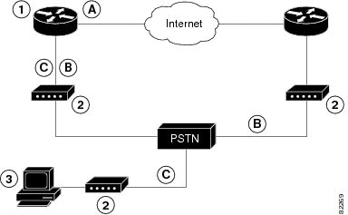
When customer premises equipment, such as a Cisco 3900 series ISR, is connected to an ISP, an IP address is dynamically assigned to the router, or the IP address is assigned by the router peer through the centrally managed function. The dial backup feature can be added to provide a failover route in case the primary line fails. Cisco 3900 series ISRs can use the auxiliary port for dial backup and remote management.
Figure 1 shows the network configuration used for remote management access and for providing backup to the primary WAN line.
Figure 1 Dial Backup and Remote Management Through the Auxiliary Port
To configure dial backup and remote management on Cisco 3900 series, Cisco 2900 series, and Cisco 1900 series ISRs, follow these steps, beginning in global configuration mode.
SUMMARY STEPS
1.![]() ip name-server server-address
ip name-server server-address
4.![]() chat-script script-name expect-send
chat-script script-name expect-send
8.![]() dialer watch-group group-number
dialer watch-group group-number
10.![]() ip nat inside source { list access-list-number } { interface type number | pool name } [ overload ]
ip nat inside source { list access-list-number } { interface type number | pool name } [ overload ]
11.![]() ip route prefix mask { ip-address | interface-type interface-number [ ip-address ]}
ip route prefix mask { ip-address | interface-type interface-number [ ip-address ]}
12.![]() access-list access-list-number { deny | permit } source [ source-wildcard ]
access-list access-list-number { deny | permit } source [ source-wildcard ]
13.![]() dialerwatch-list group-number { ip ip-address address-mask | delay route-check initial seconds }
dialerwatch-list group-number { ip ip-address address-mask | delay route-check initial seconds }
14.![]() line [ aux | console | tty | vty ] line-number [ ending-line-number ]
line [ aux | console | tty | vty ] line-number [ ending-line-number ]
17.![]() line [ aux | console | tty | vty ] line-number [ ending-line-number ]
line [ aux | console | tty | vty ] line-number [ ending-line-number ]
18.![]() flowcontrol { none | software [ lock ] [ in | out ] | hardware [ in | out ]}
flowcontrol { none | software [ lock ] [ in | out ] | hardware [ in | out ]}
DETAILED STEPS
|
|
|
|
|---|---|---|
|
|
Enters your ISP DNS IP address. |
|
|
|
Creates a DHCP address pool on the router and enters DHCP pool configuration mode. The name argument can be a string or an integer. Configure the DHCP address pool. For sample commands that you can use in DHCP pool configuration mode, see the “Example” section. |
|
|
|
Exits DHCP pool configuration mode and enters global configuration mode. |
|
chat-script script-name expect-send Router(config)# |
Configures a chat script for use in DDR to give commands for dialing a modem and for logging in to remote systems. The defined script is used to place a call over a modem connected to the PSTN. |
|
|
|
Creates asynchronous interface and enters configuration mode for the asynchronous interface. Configure the asynchronous interface. For sample commands that you can use in asynchronous interface configuration mode, see the “Example” section. |
|
|
|
Exits interface configuration mode and enters global configuration mode. |
|
|
|
Creates dialer interface and enters configuration mode for the dialer interface. |
|
dialer watch-group group-number |
||
|
|
Exits interface configuration mode and enters global configuration mode. |
|
ip nat inside source { list access-list-number } { interface type number | pool name } [ overload ] Router(config)# |
Enables dynamic translation of addresses on the inside interface. |
|
ip route prefix mask { ip-address | interface-type interface-number [ ip-address ]} |
Sets the IP route to point to the dialer interface as a default gateway. |
|
access-list access-list-number { deny | permit } source [ source-wildcard ] Router(config)# access-list 1 permit 192.168.0.0 0.0.255.255 any |
Defines an extended access list that indicates which addresses need translation. |
|
dialerwatch-list group-number { ip ip-address address-mask | delay route-check initial seconds } Router(config)# dialer watch-list 1 ip 22.0.0.2 255.255.255.255 |
Evaluates the status of the primary link, based on the existence of routes to the peer. The address 22.0.0.2 is the peer IP address of the ISP. |
|
line [ aux | console | tty | vty ] line-number [ ending-line-number ] |
||
|
|
Switches the port from console port to auxiliary port function. |
|
|
|
||
line [ aux | console | tty | vty ] line-number [ ending-line-number ] |
||
flowcontrol { none | software [ lock ] [ in | out ] | hardware [ in | out ]} |
The following configuration example specifies an IP address for the ATM interface through PPP and IP Control Protocol (IPCP) address negotiation and specifies dial backup over the console port.
Starting from Cisco IOS Release 15.3(3)M, if the second core of the CPU was disabled, then you do not need to include transport input all command in line 2. If the second core was enabled, then the transport input all command is added to the configuration.
Configuring Data Line Backup and Remote Management Through the ISDN S/T Port
This section contains the following topics:
Cisco 3900 series routers can use the ISDN S/T port for remote management. Figure 2 and Figure 3 show two typical network configurations that provide remote management access and backup for the primary WAN line.
Figure 2 shows a dial backup link that goes through a customer premises equipment (CPE) splitter, a digital subscriber line access multiplexer (DSLAM), and a central office (CO) splitter before connecting to the ISDN switch.
Figure 2 Data Line Backup Through CPE Splitter, DSLAM, and CO Splitter

Figure 3 shows a dial backup link that goes directly from the router to the ISDN switch.
Figure 3 Data Line Backup Directly from Router to ISDN Switch

Configuring ISDN Settings
Note![]() Traffic of interest must be present in order to activate the backup ISDN line by means of the backup interface and floating static routes methods. Traffic of interest is not needed in order for the dialer watch to activate the backup ISDN line.
Traffic of interest must be present in order to activate the backup ISDN line by means of the backup interface and floating static routes methods. Traffic of interest is not needed in order for the dialer watch to activate the backup ISDN line.
To configure your router ISDN interface for use as a backup interface, follow these steps, beginning in global configuration mode.
SUMMARY STEPS
1.![]() isdn switch-type switch-type
isdn switch-type switch-type
3.![]() encapsulation encapsulation-type
encapsulation encapsulation-type
5.![]() isdn switch-type switch-type
isdn switch-type switch-type
7.![]() interface dialer dialer-rotary-group-number
interface dialer dialer-rotary-group-number
9.![]() encapsulation encapsulation-type
encapsulation encapsulation-type
11.![]() dialer string dial-string# [ : isdn-subaddress ]
dialer string dial-string# [ : isdn-subaddress ]
14.![]() dialer-list dialer-group protocol protocol-name { permit | deny | list access-list-number | access-group }
dialer-list dialer-group protocol protocol-name { permit | deny | list access-list-number | access-group }
DETAILED STEPS
|
|
|
|
|---|---|---|
|
|
Specifies the ISDN switch type. The example specifies a switch type used in Australia, Europe, and the United Kingdom. For details on other supported switch types, see Cisco IOS Dial Technologies Command Reference. |
|
|
|
||
encapsulation encapsulation-type |
||
|
|
||
|
|
||
|
|
Exits interface configuration mode and enters global configuration mode. |
|
interface dialer dialer-rotary-group-number |
Creates a dialer interface (numbered 0 to 255) and enters interface configuration mode. |
|
|
|
Specifies that the IP address for the interface is obtained through PPP/IPCP (IP Control Protocol) address negotiation. The IP address is obtained from the peer. |
|
encapsulation encapsulation-type Router(config-if)# encapsulation ppp |
||
|
Router(config-if)# dialer pool 1 |
Specifies the dialer pool to be used. In the example, the dialer pool 1 setting associates the dialer 0 interface with the BRI0 interface because the BRI0 dialer pool-member value is 1. |
|
dialer string dial-string# [ : isdn-subaddress ] Router(config-if)# dialer string 384040 |
||
|
|
||
|
|
Exits dialer interface configuration mode and enters global configuration mode. |
|
dialer-list dialer-group protocol protocol-name { permit | deny | list access-list-number | access-group } |
Creates a dialer list for packets of interest to be forwarded through the specified interface dialer group. In the example, dialer-list 1 corresponds to dialer-group 1. For details about this command and additional parameters that can be set, see Cisco IOS Dial Technologies Command Reference. |
Example
The following configuration example configures an aggregated and ISDN peer router.
The aggregator is typically a concentrator router where your Cisco router Asynchronous Transfer Mode (ATM) permanent virtual connection (PVC) terminates. In the following configuration example, the aggregator is configured as a PPP over Ethernet (PPPoE) server.
The ISDN peer router is any router that has an ISDN interface and can communicate through a public ISDN network to reach your Cisco router ISDN interface. The ISDN peer router provides Internet access for your Cisco router during the ATM network downtime.
Configuring Third-Party SFPs
Small Form-Factor Pluggables (SFPs) that are not Cisco certified are called third-party SFPs. Cisco approved means the SFPs have undergone rigorous testing with Cisco products and the SFPs are guaranteed to have 100% compatibility.
Third-party SFPs are manufactured by companies that are not on the Cisco-approved Vendor List (AVL). Currently, Cisco ISR G2 routers support only Cisco-approved SFPs. From Release 15.3(2)T, Cisco ISR G2 routers recognize third-party SFPs.
Note![]() Cisco does not provide any kind of support for the third-party SFPs because they are not validated by Cisco.
Cisco does not provide any kind of support for the third-party SFPs because they are not validated by Cisco.
Restrictions
- Supports only 100BASE SFPs and 1000BASE SFPs under two speed configurations:
- 100 Mbps speed for 100BASE SFPs
- 1000 Mbps speed for 1000BASE SFPs
- Only the following routers and modules support third-party SFPs:
- Cisco 2921 Integrated Services Router
- Cisco 2951 Integrated Services Router
- Cisco 3900 Integrated Services Router
- Cisco 3900E Series Integrated Services Routers
- Cisco 892-F Gigabit Ethernet Security Router
- Cisco 898-EA Gigabit Ethernet Security Router
- EHWIC-1GE-SFP
SUMMARY STEPS
3.![]() service unsupported-transceiver
service unsupported-transceiver
DETAILED STEPS
Examples
This example shows how to configure a third-party SFP on a Cisco ISR G2 Series Router:
 Feedback