- Preface
- NPE-100, NPE-150, and NPE-200 Overview
- NPE-175 and NPE-225 Overview
- NPE-300 and NPE-400 Overview
- NSE-1 Overview
- NPE-G1 Overview
- NPE-G2 Overview
- NPE-G1 and NPE-G2 Installation and Configuration Information
- Preparation for Installation
- Removing and Installing the NPE or NSE
- Configuration Tasks and Troubleshooting Information
Network Processing Engine and Network Services Engine Installation and Configuration
Bias-Free Language
The documentation set for this product strives to use bias-free language. For the purposes of this documentation set, bias-free is defined as language that does not imply discrimination based on age, disability, gender, racial identity, ethnic identity, sexual orientation, socioeconomic status, and intersectionality. Exceptions may be present in the documentation due to language that is hardcoded in the user interfaces of the product software, language used based on RFP documentation, or language that is used by a referenced third-party product. Learn more about how Cisco is using Inclusive Language.
- Updated:
- November 30, 2006
Chapter: NPE-G1 Overview
NPE-G1 Overview
This chapter describes the NPE-G1 and contains the following sections:
•![]() NPE-G1 Description and Overview
NPE-G1 Description and Overview
•![]() Connection Equipment and Specifications
Connection Equipment and Specifications
•![]() Fiber Optic Cleaning Information
Fiber Optic Cleaning Information

For general preparation for installation instructions, see Chapter 8, "Preparation for Installation." For installation and configuration instructions specific to the NPE-G1, see Chapter 7, "NPE-G1 and NPE-G2 Installation and Configuration Information."
Supported Platforms
The NPE-G1 is supported only in the Cisco 7200 VXR routers, the Cisco uBR7246VXR universal broadband router, and the Cisco uBR7225VXR universal broadband router. For the Cisco 7200 VXR routers, order Part Number NPE-G1 or NPE-G1=. For the Cisco uBR7246VXR and Cisco uBR7225VXR routers, order Part Number UBR7200-NPE-G1 or UBR7200-NPE-G1=.

Note ![]() Unless otherwise indicated, all references to NPE-G1 in this document also refer to UBR7200-NPE-G1.
Unless otherwise indicated, all references to NPE-G1 in this document also refer to UBR7200-NPE-G1.
Software Requirements
For minimum software release information, see the "Software Requirements" section on page 8-4.
NPE-G1 Description and Overview
This section contains information about the NPE-G1 components and the system management functions. The NPE-G1 is the first net
processing engine for the Cisco 7200 VXR routers and Cisco uBR7200 series routers to provide the functionality of both a network processing engine and I/O controller. If used without an I/O controller, an I/O controller blank panel must be in place.
While its design provides I/O controller functionality, it can also work with any I/O controller supported in the Cisco 7200 VXR routers and Cisco uBR7200 series routers. The NPE-G1, when installed with an I/O controller, provides the bootflash and NVRAM that the Cisco IOS software uses to boot.
Note ![]() An I/O controller can be used with the NPE-G1, but an I/O controller is not necessary for system functionality. Installing an I/O controller in a chassis with the NPE-G1 activates the console and auxiliary ports on the I/O controller and automatically disables the console and auxiliary ports on the NPE-G1. However, you can still use the CompactFlash Disk slots and Ethernet ports on both the NPE-G1 and I/O controller when both cards are installed.
An I/O controller can be used with the NPE-G1, but an I/O controller is not necessary for system functionality. Installing an I/O controller in a chassis with the NPE-G1 activates the console and auxiliary ports on the I/O controller and automatically disables the console and auxiliary ports on the NPE-G1. However, you can still use the CompactFlash Disk slots and Ethernet ports on both the NPE-G1 and I/O controller when both cards are installed.
The NPE-G1 maintains and executes the system management functions for the Cisco 7200 VXR routers and Cisco uBR7200 series routers and also holds the system memory and environmental monitoring functions.
The NPE-G1 consists of one board with multiple interfaces. It can be used only in the Cisco 7200 VXR routers and Cisco uBR7200 series routers.
Note ![]() The Cisco 7200 VXR routers and Cisco uBR7200 series routers use different models of the NPE-G1 processor. For the Cisco 7200 VXR routers , order the NPE-G1 or NPE-G1= product. For the Cisco uBR7200 series router, order the UBR7200-NPE-G1 or UBR7200-NPE-G1= product. The two models of NPE-G1 have different labels and use different boot helper images, and they cannot be interchanged between the Cisco 7200 VXR routers and Cisco uBR7200 series routers.
The Cisco 7200 VXR routers and Cisco uBR7200 series routers use different models of the NPE-G1 processor. For the Cisco 7200 VXR routers , order the NPE-G1 or NPE-G1= product. For the Cisco uBR7200 series router, order the UBR7200-NPE-G1 or UBR7200-NPE-G1= product. The two models of NPE-G1 have different labels and use different boot helper images, and they cannot be interchanged between the Cisco 7200 VXR routers and Cisco uBR7200 series routers.
Bandwidth
The NPE-G1 uses no bandwidth points, and when used with any I/O controller, the I/O controller also uses no bandwidth points. None of the Gigabit Ethernet interfaces on the NPE-G1 use bandwidth points.
Components
Figure 5-1 illustrates the NPE-G1 and its major components.
Figure 5-1 NPE-G1
|
|
Midplane connectors |
|
Boot ROM |
|
|
Flash memory |
|
NVRAM |
|
|
Temperature sensor |
|
SODIMM 2 (J4) |
|
|
BCM1250 system |
|
Temperature sensor |
|
|
Keying post |
|
SODIMM 1 (J3) |
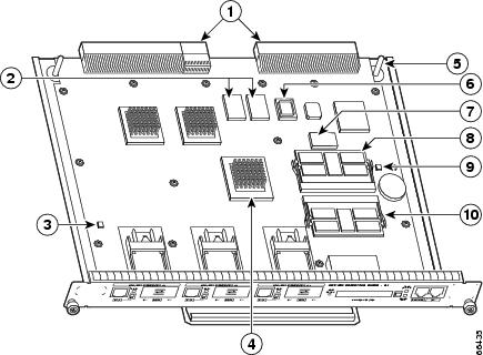
The NPE-G1 consists of the following components:
•![]() BCM1250 system
BCM1250 system
–![]() Microprocessor operates at an internal clock speed of 700 MHz.
Microprocessor operates at an internal clock speed of 700 MHz.
–![]() Hardware logic to interconnect the processor, double data rate synchronous dynamic random-access memory (DDR-SDRAM), lightning data transport (LDT) bus, the generic PCI bus, and three direct-interface Gigabit Ethernet interfaces.
Hardware logic to interconnect the processor, double data rate synchronous dynamic random-access memory (DDR-SDRAM), lightning data transport (LDT) bus, the generic PCI bus, and three direct-interface Gigabit Ethernet interfaces.
•![]() Cache memory
Cache memory
The NPE-G1 has two levels of cache: primary and secondary cache that are internal to the microprocessor with secondary unified cache for data and instruction.
•![]() The NPE-G1 uses DDR-SDRAM for providing code, data, and packet storage.
The NPE-G1 uses DDR-SDRAM for providing code, data, and packet storage.
•![]() Two environmental sensors for monitoring the cooling air as it enters and leaves the chassis.
Two environmental sensors for monitoring the cooling air as it enters and leaves the chassis.
•![]() Full-feature I/O controller functionality
Full-feature I/O controller functionality
–![]() Three Gigabit Ethernet interfaces (six ports: three GBIC [optical] and three RJ-45s [copper]). Any three ports are available at the same time and are linked directly to the BCM1250 system; therefore the interfaces are not charged bandwidth points.
Three Gigabit Ethernet interfaces (six ports: three GBIC [optical] and three RJ-45s [copper]). Any three ports are available at the same time and are linked directly to the BCM1250 system; therefore the interfaces are not charged bandwidth points.
–![]() CompactFlash Disk for storing the default Cisco IOS software image. The CompactFlash Disk slot can be used whether or not an I/O controller is in the router.
CompactFlash Disk for storing the default Cisco IOS software image. The CompactFlash Disk slot can be used whether or not an I/O controller is in the router.
–![]() Auxiliary port with full data terminal equipment (DTE) functionality. (Functional when an I/O controller is not present. If an I/O controller is present, its auxiliary port is the default port.)
Auxiliary port with full data terminal equipment (DTE) functionality. (Functional when an I/O controller is not present. If an I/O controller is present, its auxiliary port is the default port.)
–![]() Console port with full data communications equipment (DCE) functionality. (Functional when an I/O controller is not present. If an I/O controller is present, its console port is the default port.)
Console port with full data communications equipment (DCE) functionality. (Functional when an I/O controller is not present. If an I/O controller is present, its console port is the default port.)
–![]() Boot ROM for storing sufficient code for booting the Cisco IOS software.
Boot ROM for storing sufficient code for booting the Cisco IOS software.
–![]() Flash memory for storing the boot helper (boot loader) image. (The boot helper image comes installed on the NPE-G1.) If an I/O controller is present, its flash memory is no longer available.
Flash memory for storing the boot helper (boot loader) image. (The boot helper image comes installed on the NPE-G1.) If an I/O controller is present, its flash memory is no longer available.
–![]() NVRAM for storing the system configuration and environmental monitoring logs. NVRAM uses lithium batteries to maintain its contents when disconnected from power. If an I/O controller is present, its NVRAM memory is no longer available.
NVRAM for storing the system configuration and environmental monitoring logs. NVRAM uses lithium batteries to maintain its contents when disconnected from power. If an I/O controller is present, its NVRAM memory is no longer available.
–![]() Upgradable memory modules
Upgradable memory modules
Note ![]() An I/O controller can be used with the NPE-G1, but an I/O controller is not necessary for system functionality. Installing an I/O controller in a chassis with the NPE-G1 activates the console and auxiliary ports on the I/O controller and automatically disables the console and auxiliary ports on the NPE-G1. However, you can still use the CompactFlash Disk slots and Ethernet ports on both the NPE-G1 and I/O controller when both cards are installed.
An I/O controller can be used with the NPE-G1, but an I/O controller is not necessary for system functionality. Installing an I/O controller in a chassis with the NPE-G1 activates the console and auxiliary ports on the I/O controller and automatically disables the console and auxiliary ports on the NPE-G1. However, you can still use the CompactFlash Disk slots and Ethernet ports on both the NPE-G1 and I/O controller when both cards are installed.
Interfaces and LEDs
Figure 5-2 NPE-G1 Interfaces
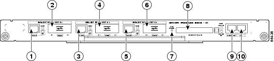
The three interfaces on the NPE-G1 consist of three Gigabit Interface Converter (GBIC) ports and three 10/100/1000 Fast Ethernet/Gigabit Ethernet ports. The rules for using these ports are:
•![]() Only one port per interface can be used at any one time. For example, for interface Gigabit Ethernet 0/1, either the RJ-45 port can be used or the GBIC port, but not both.
Only one port per interface can be used at any one time. For example, for interface Gigabit Ethernet 0/1, either the RJ-45 port can be used or the GBIC port, but not both.
•![]() A total of three ports on any of the three interfaces (0/1, 0/2, or 0/3) can be used at any one time; for example, 0/1 GBIC, 0/2 GBIC, and 0/3 RJ-45.
A total of three ports on any of the three interfaces (0/1, 0/2, or 0/3) can be used at any one time; for example, 0/1 GBIC, 0/2 GBIC, and 0/3 RJ-45.
•![]() The port numbering for the interfaces on the NPE-G1 start with 0/1 and not with 0/0, as is typical for other interface cards. This is to avoid conflicts with the Ethernet and FastEthernet ports on an I/O controller, if it is also installed.
The port numbering for the interfaces on the NPE-G1 start with 0/1 and not with 0/0, as is typical for other interface cards. This is to avoid conflicts with the Ethernet and FastEthernet ports on an I/O controller, if it is also installed.
Figure 5-3 NPE-G1 LEDs
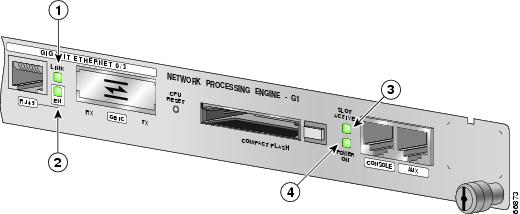
The NPE-G1 faceplate contains LEDs that indicate system and port status. The RJ-45 and GBIC ports share the same LINK LED because only one of these ports per interface (0/1, 0/2, or 0/3) can be used at any one time. The EN (Enable) LED is on if the RJ-45 port is in use.
The POWER ON LED is on whether or not an I/O controller is present in the router. The CompactFlash Disk slot can be used whether or not an I/O controller is present in the router. The SLOT ACTIVE LED is on only when the CompactFlash Disk slot is in use.
LEDs are either on or off. The LED state (on or off), not the color, determines the status of the connection.
CompactFlash Disk
The NPE-G1 has one CompactFlash Disk slot that uses CompactFlash Disks. The device in this slot is always addressed as disk2: when using Cisco IOS CLI commands.
CompactFlash Disks are smaller in size than Type 2 Flash Disks but provide the same Attachment (ATA) interface and equivalent functionality. This interface complies with the ANSI ATA Interface Document X3T13.1153 D Rev. 9 specification. CompactFlash Disks provide from 64 MB to 256 MB of storage space.
The CompactFlash Disk has controller circuitry that allows it to emulate a hard disk and automatically maps out bad blocks and performs automatic block erasure. The CompactFlash Disk also provides the capability to allocate noncontiguous sectors, which eliminates the need for the squeeze command (which was required with older-style linear flash memory cards to recover the space used by deleted files).
The CompactFlash Disk also supports the Cisco IOS File System feature, which provides a single interface to all of the router's file systems, including the Flash Disks and flash memory, as well as network file systems such as File Transfer Protocol (FTP) and Trivial FTP (TFTP) servers.
To install a CompactFlash Disk in the CompactFlash Disk slot, complete the following steps.
Step 1 ![]() Attach an ESD wrist or ankle strap, connecting the equipment end of the strap to an unfinished chassis surface.
Attach an ESD wrist or ankle strap, connecting the equipment end of the strap to an unfinished chassis surface.
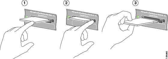
Step 2 ![]() Orient the CompactFlash Disk so that its connector end faces the appropriate slot. (See 1 in Figure 5-4.)
Orient the CompactFlash Disk so that its connector end faces the appropriate slot. (See 1 in Figure 5-4.)
Figure 5-4 Installing and Removing a CompactFlash Disk
|
|
Inserting the compact Flash Disk |
|
Removing the CompactFlash Disk |
|
|
Pressing the ejector button to release the CompactFlash Disk |
Step 3 ![]() Carefully insert the CompactFlash Disk into the slot until it completely seats in the connector, and the ejector button for the slot pops out toward you. (See 2 in Figure 5-4.)
Carefully insert the CompactFlash Disk into the slot until it completely seats in the connector, and the ejector button for the slot pops out toward you. (See 2 in Figure 5-4.)
Note ![]() The CompactFlash Disk is keyed and cannot be seated the wrong way. The ejector button does not pop out if the CompactFlash Disk is not completely inserted.
The CompactFlash Disk is keyed and cannot be seated the wrong way. The ejector button does not pop out if the CompactFlash Disk is not completely inserted.
To remove a CompactFlash Disk from the CompactFlash Disk slot, complete the following steps:
Step 1 ![]() Press the ejector button on the slot. (See 3 in Figure 5-4.)
Press the ejector button on the slot. (See 3 in Figure 5-4.)
Step 2 ![]() Grasp the CompactFlash Disk and pull it from the slot.
Grasp the CompactFlash Disk and pull it from the slot.
Step 3 ![]() Place the CompactFlash Disk in an antistatic bag.
Place the CompactFlash Disk in an antistatic bag.
Note ![]() All CompactFlash Disks must be formatted before their initial use. CompactFlash Disks shipped with the NPE-G1 are formatted at the factory, but spare memory cards are not formatted.
All CompactFlash Disks must be formatted before their initial use. CompactFlash Disks shipped with the NPE-G1 are formatted at the factory, but spare memory cards are not formatted.
Summary of Important NPE-G1 Information
For general preparation for installation instructions, see Chapter 8, "Preparation for Installation." For installation and configuration instructions specific to the NPE-G1, see Chapter 7, "NPE-G1 and NPE-G2 Installation and Configuration Information."
•![]() The RJ-45 ports and GBIC ports are both reported in software as GigabitEthernet 0/1, GigabitEthernet 0/2, and GigabitEthernet 0/3. Only one of the pair of interface ports can be used at a time; for example, GBIC GigabitEthernet 0/2 or RJ-45 GigabitEthernet 0/2.
The RJ-45 ports and GBIC ports are both reported in software as GigabitEthernet 0/1, GigabitEthernet 0/2, and GigabitEthernet 0/3. Only one of the pair of interface ports can be used at a time; for example, GBIC GigabitEthernet 0/2 or RJ-45 GigabitEthernet 0/2.
•![]() The I/O controller GE/E interface reports GigabitEthernet 0/0 and Ethernet 0/0, and the I/O controller 2FE/E interface reports FastEthernet 0/0 and FastEthernet 0/1.
The I/O controller GE/E interface reports GigabitEthernet 0/0 and Ethernet 0/0, and the I/O controller 2FE/E interface reports FastEthernet 0/0 and FastEthernet 0/1.
•![]() If the RJ-45 port is in use, the EN (Enable) LED is on. If the GBIC is in use, the EN (Enable) LED is off.
If the RJ-45 port is in use, the EN (Enable) LED is on. If the GBIC is in use, the EN (Enable) LED is off.
•![]() With the NPE-G1 and an I/O controller both installed, the I/O controller functionality on the NPE-G1 is shared with that of the I/O controller.
With the NPE-G1 and an I/O controller both installed, the I/O controller functionality on the NPE-G1 is shared with that of the I/O controller.
•![]() When both an NPE-G1 and an I/O controller are installed, the flash memory and NVRAM of the NPE-G1 are enabled and the flash memory and NVRAM on the I/O controller are no longer accessible.
When both an NPE-G1 and an I/O controller are installed, the flash memory and NVRAM of the NPE-G1 are enabled and the flash memory and NVRAM on the I/O controller are no longer accessible.
•![]() The console and auxiliary ports on the NPE-G1 are disabled by Cisco IOS when an I/O controller is present; the console and auxiliary ports on the I/O controller are active.
The console and auxiliary ports on the NPE-G1 are disabled by Cisco IOS when an I/O controller is present; the console and auxiliary ports on the I/O controller are active.
•![]() Console port messages can be routed to the auxiliary port on either the NPE-G1 or on the I/O controller.
Console port messages can be routed to the auxiliary port on either the NPE-G1 or on the I/O controller.
•![]() The default media is the RJ-45 port. To change the media type, use the media-type command.
The default media is the RJ-45 port. To change the media type, use the media-type command.
•![]() Only the port selected by the media-type command is active. A cable attached to the other of the RJ-45 and GBIC pair will be ignored. For example, if GBIC GigabitEthernet 0/2 is selected using the media-type command, RJ-45 GigabitEthernet 0/2 is ignored, even if a cable is attached to
Only the port selected by the media-type command is active. A cable attached to the other of the RJ-45 and GBIC pair will be ignored. For example, if GBIC GigabitEthernet 0/2 is selected using the media-type command, RJ-45 GigabitEthernet 0/2 is ignored, even if a cable is attached to
RJ-45 0/2.
•![]() The NPE-G1 uses no bandwidth points, and when used with any I/O controller, the I/O controller also uses no bandwidth points. None of the Gigabit Ethernet interfaces on the NPE-G1 use bandwidth points.
The NPE-G1 uses no bandwidth points, and when used with any I/O controller, the I/O controller also uses no bandwidth points. None of the Gigabit Ethernet interfaces on the NPE-G1 use bandwidth points.
•![]() The CompactFlash Disk on the NPE-G1 is available at all times, with or without an I/O controller installed. The CompactFlash Disk is always addressed as the disk2 device, to avoid conflicts with the disk0 and disk1 devices on the I/O controller, if the I/O controller is also installed.
The CompactFlash Disk on the NPE-G1 is available at all times, with or without an I/O controller installed. The CompactFlash Disk is always addressed as the disk2 device, to avoid conflicts with the disk0 and disk1 devices on the I/O controller, if the I/O controller is also installed.
Note ![]() The Gigabit Ethernet interfaces on the NPE-G1 do not support the Inter-Switch Link (ISL) VLAN encapsulation protocol. We recommend that customers use the IEEE 802.1Q VLAN encapsulation protocol as an alternative. Where an application requires the use of ISL, this can be provided by the Fast Ethernet or Gigabit Ethernet port adapters or I/O controllers.
The Gigabit Ethernet interfaces on the NPE-G1 do not support the Inter-Switch Link (ISL) VLAN encapsulation protocol. We recommend that customers use the IEEE 802.1Q VLAN encapsulation protocol as an alternative. Where an application requires the use of ISL, this can be provided by the Fast Ethernet or Gigabit Ethernet port adapters or I/O controllers.
System Management Functions
The NPE-G1 performs the following system management functions:
•![]() Sending and receiving routing protocol updates
Sending and receiving routing protocol updates
•![]() Managing tables, caches, and buffers
Managing tables, caches, and buffers
•![]() Monitoring interface and environmental status
Monitoring interface and environmental status
•![]() Providing Simple Network Management Protocol (SNMP) management through the console and Telnet interface
Providing Simple Network Management Protocol (SNMP) management through the console and Telnet interface
•![]() Accounting for and switching of data traffic
Accounting for and switching of data traffic
•![]() Booting and reloading images
Booting and reloading images
•![]() Managing port adapters (including recognition and initialization during online insertion and removal)
Managing port adapters (including recognition and initialization during online insertion and removal)
Terms and Acronyms
•![]() Boot ROM—Read-only memory that stores the boot image for bringing up the Cisco IOS image
Boot ROM—Read-only memory that stores the boot image for bringing up the Cisco IOS image
•![]() Cache—Memory with fast access and small capacity used to temporarily store recently accessed data; found either incorporated into the processor or near it
Cache—Memory with fast access and small capacity used to temporarily store recently accessed data; found either incorporated into the processor or near it
•![]() DDR SDRAM—double data rate synchronous dynamic random-access memory
DDR SDRAM—double data rate synchronous dynamic random-access memory
•![]() CWDM GBIC—Coarse Wavelength-Division Multiplexing Gigabit Interface Converter
CWDM GBIC—Coarse Wavelength-Division Multiplexing Gigabit Interface Converter
•![]() Flash memory—Location where the basic boot image is stored
Flash memory—Location where the basic boot image is stored
•![]() Instruction and data cache—Instructions to the processor, and data on which the instructions work
Instruction and data cache—Instructions to the processor, and data on which the instructions work
•![]() Integrated cache—Cache that is built into the processor; sometimes referred to as internal cache. Cache memory physically located outside the processor is not integrated, and is sometimes referred to as external cache.
Integrated cache—Cache that is built into the processor; sometimes referred to as internal cache. Cache memory physically located outside the processor is not integrated, and is sometimes referred to as external cache.
•![]() LDT bus—lightning data transport bus
LDT bus—lightning data transport bus
•![]() NVRAM—nonvolatile random-access memory
NVRAM—nonvolatile random-access memory
•![]() OTP—one time programmable
OTP—one time programmable
•![]() Primary and secondary cache—Hierarchical cache memory storage based on the proximity of the cache to the core of the processor. Primary cache is closest to the processor core and has the fastest access. Secondary cache has slower access than primary cache.
Primary and secondary cache—Hierarchical cache memory storage based on the proximity of the cache to the core of the processor. Primary cache is closest to the processor core and has the fastest access. Secondary cache has slower access than primary cache.
•![]() RAM—random-access memory
RAM—random-access memory
•![]() RISC—reduced instruction set computing
RISC—reduced instruction set computing
•![]() ROM—read-only memory
ROM—read-only memory
•![]() SDRAM—synchronous dynamic random-access memory
SDRAM—synchronous dynamic random-access memory
•![]() SDRAM-fixed—SDRAM of a fixed size or quantity; can be replaced, but not upgraded
SDRAM-fixed—SDRAM of a fixed size or quantity; can be replaced, but not upgraded
•![]() SODIMM—small outline dual in-line memory module
SODIMM—small outline dual in-line memory module
•![]() Unified cache—Instruction cache and data cache are combined. For example, a processor may have primary cache with separate instruction and data cache memory, but unified secondary cache.
Unified cache—Instruction cache and data cache are combined. For example, a processor may have primary cache with separate instruction and data cache memory, but unified secondary cache.
NPE-G1 Memory Information
To determine the memory configuration of your NPE-G1, use the show version command.
The following example shows an NPE-G1 installed in a Cisco 7206VXR router. The display for a Cisco uBR7246VXR router is similar.
Router# show version
Cisco Internetwork Operating System Software
IOS (tm) 7200 Software (C7200-P-M), Experimental Version
12.2(20011112:161132)
Copyright (c) 1986-2001 by cisco Systems, Inc.
Compiled Tue 13-Nov-01 03:58 by
Image text-base:0x600089B8, data-base:0x6130A000
(display text omitted)
cisco 7206VXR (NPE-G1) processor (revision 0x00) with 245760K/16384K
bytes of memory.
Processor board ID 15191620
BCM12500 CPU at 700Mhz, Implementation 1, Rev 0.1, 512KB L2 Cache
6 slot VXR midplane, Version 2.0
(display text omitted)
Table 5-1 provides memory specifications and Table 5-2 provides user replaceable memory configuration information for the NPE-G1. Table 5-3 provides CompactFlash Disk specifications.
|
|
|
|
|
|
|---|---|---|---|---|
SDRAM |
128 MB, 256 MB, 512 MB |
2 |
128-MB, 256-MB, or 512-MB SODIMMs1 |
J3 and J4 |
Boot ROM |
512 KB |
1 |
Reprogrammable Boot ROM for the ROM monitor program |
U1 |
Flash memory |
16 MB |
1 |
Contains the default boot helper (boot loader) image |
U25 and U26 |
NVRAM |
512 KB |
1 |
Nonvolatile EPROM for the system configuration file |
U7 |
Primary cache |
32 KB (16 KB instruction, 16 KB data) |
— |
BCM1250 system, internal cache |
U22 |
Secondary cache |
512 KB |
— |
BCM1250 system, internal, unified cache |
U22 |
1 The NPE-G1 requires that locations J3 and J4 always contain two SODIMMs of the same size. |
|
|
|
|---|---|
64 MB |
MEM-NPE-G1-FLD64= |
128 MB |
MEM-NPE-G1-FLD128= |
256 MB |
MEM-NPE-G1-FLD256= |
Connection Equipment and Specifications
This section contains connection equipment and pinout information for the Gigabit Ethernet RJ-45 ports, Gigabit Interface Converter (GBIC) ports, console port, and auxiliary port that are located on the NPE-G1.
Ethernet and Fast Ethernet RJ-45 Connection Equipment
The NPE-G1 has RJ-45 ports for Ethernet, Fast Ethernet, and Gigabit Ethernet or autosensing Ethernet, Fast Ethernet, and Gigabit Ethernet connections. The RJ-45 port supports IEEE 802.3 (Ethernet) and IEEE 802.3u (Fast Ethernet) interfaces compliant with 10BASET, 100BASETX, and 1000BASET and 1000BASEX specifications.
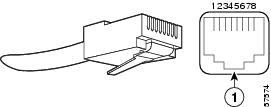
The RJ-45 ports support standard straight-through and crossover Category 5 UTP cables with RJ-45 connectors. (See Figure 5-5) Cisco does not supply Category 5 UTP cables; these cables are available commercially.
Note ![]() To comply with EMI EN55022 Class B regulations, shielded Ethernet cables must be used with the UBR7200-NPE-G1 in the Cisco uBR7246VXR router. Three shielded cables are included with the UBR7200-NPE-G1.
To comply with EMI EN55022 Class B regulations, shielded Ethernet cables must be used with the UBR7200-NPE-G1 in the Cisco uBR7246VXR router. Three shielded cables are included with the UBR7200-NPE-G1.
Figure 5-5 shows an RJ-45 port and connector. Table 5-4Table 5-4 lists the pinouts and signals for the RJ-45 port.
Figure 5-5 RJ-45 Port and Connector
|
|
RJ-45 connector |

Warning ![]() To avoid electric shock, do not connect safety extra-low voltage (SELV) circuits to telephone-network voltage (TNV) circuits. LAN ports contain SELV circuits, and WAN ports contain TNV circuits. Some LAN and WAN ports both use RJ-45 connectors. Use caution when connecting cables. Statement 1021
To avoid electric shock, do not connect safety extra-low voltage (SELV) circuits to telephone-network voltage (TNV) circuits. LAN ports contain SELV circuits, and WAN ports contain TNV circuits. Some LAN and WAN ports both use RJ-45 connectors. Use caution when connecting cables. Statement 1021
|
|
|
|
1 |
Tx Data+1 |
Tx A+ |
2 |
Tx Data- |
Tx A- |
3 |
Rx Data+2 |
Rx B+ |
4 |
N/C |
Tx C+ |
5 |
N/C |
Tx C- |
6 |
Rx Data- |
Rx B- |
7 |
N/C |
Rx D+ |
8 |
NC |
Rx D- |
1 Tx Data = Transmit Data 2 Rx Data = Receive Data |
Note ![]() With reference to the RJ-45 pinout in Table 5-4Table 5-4, proper common-mode line terminations should be used for the unused Category 5 UTP cable pairs 4/5 and 7/8. Common-mode termination reduces electromagnetic interference (EMI).
With reference to the RJ-45 pinout in Table 5-4Table 5-4, proper common-mode line terminations should be used for the unused Category 5 UTP cable pairs 4/5 and 7/8. Common-mode termination reduces electromagnetic interference (EMI).
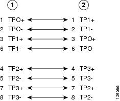
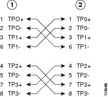
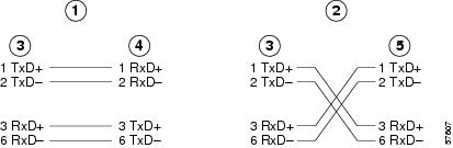
Depending on your RJ-45 interface cabling requirements, use the pinouts shown in Figure 5-6 and Figure 5-7 for Gigabit Ethernet straight-through and crossover twisted-pair cable connections. Use Figure 5-8 for Ethernet/Fast Ethernet straight-through and crossover twisted-pair cable connections.
Figure 5-6 Four Twisted-Pair Straight-Through Cable Schematics for 10/100/1000 and 1000BASET GBIC Module Ports
|
|
Router |
|
Hub |
Figure 5-7 Four Twisted-Pair Crossover Cable Schematics for 10/100/1000 and 1000BASET GBIC Module Ports
|
|
Router |
|
Hub |
Figure 5-8 Ethernet/Fast Ethernet Straight-Through and Crossover Cable Pinouts
|
|
Straight-through cable pinout, Ethernet port to a hub or repeater |
|
Hub |
|
|
Crossover cable pinout, Ethernet port to a DTE |
|
DTE |
|
|
Ethernet port |
For straight-through and crossover cable information, see the "Console and Auxiliary Port Connection Equipment" section.
Gigabit Ethernet GBIC Connection Equipment
The Gigabit Interface Converter (GBIC) port is a 1000-Mbps optical interface in the form of an SC-type duplex port that supports IEEE 802.3z interfaces compliant with the 1000BASEX standard. (See Figure 5-10.)
Note ![]() The GBIC is a separately orderable part and does not ship installed in your NPE-G1. You must install the GBIC before you connect the cables to it. (For GBIC installation and cabling instructions, refer to the Installing the Gigabit Interface Converter document that shipped with your GBIC.)
The GBIC is a separately orderable part and does not ship installed in your NPE-G1. You must install the GBIC before you connect the cables to it. (For GBIC installation and cabling instructions, refer to the Installing the Gigabit Interface Converter document that shipped with your GBIC.)
Warning ![]() Because invisible laser radiation may be emitted from the aperture of the port when no cable is connected, avoid exposure to laser radiation and do not stare into open apertures. Statement 70
Because invisible laser radiation may be emitted from the aperture of the port when no cable is connected, avoid exposure to laser radiation and do not stare into open apertures. Statement 70
Figure 5-9 shows the Class 1 warning label that appears on the Gigabit Ethernet optical ports.
Figure 5-9 Laser Class 1 Warning Label

Warning ![]() Class 1 Laser Product. Statement 1008
Class 1 Laser Product. Statement 1008
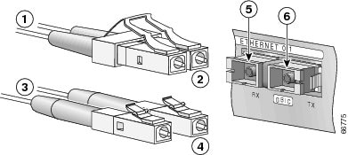
Figure 5-10 shows the simplex and duplex SC-type connectors on your multimode or single-mode optical fiber cables. For simplex connectors, two cables are required, one cable for transmit (TX) and a second cable for receive (RX). For duplex connectors, only one cable that has both TX and RX connectors is required. You can use either simplex or duplex connectors for the NPE-G1.
Figure 5-10 GBIC Port Connections
|
|
To external 1000BASEX network |
|
RX (GBIC port 0/1) |
|
|
1 duplex connector (TX and RX) |
|
TX (GBIC port 0/1) |
|
|
To external 1000BASEX network |
||
|
|
2 simplex connectors |
Table 5-5 describes the available GBIC options.
Table 5-6 lists the available CWDM GBIC options.
Table 5-7 provides cabling specifications for the GBICs that you install in Gigabit Ethernet devices. Note that all GBIC ports have SC-type connectors. Also, the minimum cable distance for the WS-G5484 or GBIC-SX and WS-G5486 or GBIC-LX/LH (multimode fiber [MMF] and single-mode fiber [SMF]) is 6.5 feet (2 m), and the minimum link distance for the WS-G5487 or GBIC-ZX is 6.2 miles (10 km) with an 8-dB attenuator installed at each end of the link. Without attenuators, the minimum link distance for the WS-G5487 or GBIC-ZX is 24.9 miles (40 km).
Note ![]() Optical fiber cables are commercially available; they are not available from Cisco.
Optical fiber cables are commercially available; they are not available from Cisco.
|
|
|
|
|
|
Cable Distance |
|---|---|---|---|---|---|
WS-G5484 or GBIC-SX |
850 |
MMF1 |
62.5 |
160 |
722 ft (220 m) |
62.5 |
200 |
902 ft (275 m) |
|||
50.0 |
400 |
1640 ft (500 m) |
|||
50.0 |
500 |
1804 ft (550 m) |
|||
WS-G5486 or GBIC-LX/LH |
1300 |
MMF2 and SMF |
62.5 |
500 |
1804 ft (550 m) |
50.0 |
400 |
1804 ft (550 m) |
|||
50.0 |
500 |
1804 ft (550 m) |
|||
9/10 |
— |
6.2 miles (10 km) |
|||
WS-G5487 or GBIC-ZX |
1550 |
SMF |
9/10 |
— |
43.5 miles (70 km) |
SMF3 |
8 |
— |
62.1 miles (100 km) |
1 Multimode fiber (MMF) only. 2 A mode-conditioning patch cord is required. 3 Dispersion-shifted single-mode optical fiber cable. 3 Table 5-8 provides the GBIC transmit and receive power requirements and power budget. |
|
|
|
|
|
||
|---|---|---|---|---|---|
WS-G5484 or GBIC-SX |
-9.5 dBm1 |
-4 dBm1 |
-17 dBm |
0 dBm |
7.5 dBm2 |
WS-G5486 or GBIC-LX/LH |
-9.5 dBm3 -11.5dBm4 |
-3 dBm5 |
-20 dBm |
-3 dBm |
|
WS-G5487 or GBIC-ZX |
0 dBm |
5.2 dBm |
-24 dBm |
-3 dBm |
-24 dBm |
1 For fiber types 50/125 mm, NA = 0.20 fiber and 62.5/125 mm, NA = 0.275 fiber. 2 For fiber types 50 mm MMF and 62.5 mm MMF. 3 For fiber types 9/125 mm SMF. 4 For fiber types 62.5/125 mm MMF and 50/125 mm MMF. 5 For fiber types 9/125 mm SMF, 62.5/125 mm MMF, and 50/125 mm MMF. 6 For fiber types 50 mm MMF and 62.5 mm MMF. 7 For fiber type 10 mm SMF. |
Mode-Conditioning Patch Cord Description
A mode-conditioning patch cord can be used with the WS-G5486= or GBIC-LX/LH= to allow reliable laser transmission between the single-mode laser source on the GBIC and a multimode optical fiber cable.
When an unconditioned laser source designed for operation on single-mode optical fiber is directly coupled to a multimode optical fiber cable, an effect known as differential mode delay (DMD) might result in a degradation of the modal bandwidth of the optical fiber cable.
This degradation results in a decrease in the link span (the distance between a transmitter and a receiver) that can be supported reliably. The effect of DMD can be overcome by conditioning the launch characteristics of a laser source. A practical means of performing this conditioning is to use a device called a mode-conditioning patch cord.
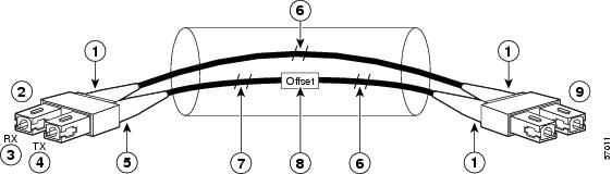
A mode-conditioning patch cord is an optical fiber cable assembly that consists of a pair of optical fibers terminated with connector hardware. Specifically, the mode-conditioning patch cord is composed of a single-mode optical fiber permanently coupled off-center (see Offset in Figure 5-11) to a graded-index multimode optical fiber. Figure 5-11 shows a diagram of the mode-conditioning patch cord assembly.
Figure 5-11 Mode Conditioning Patch Cord
|
|
Beige color identifier |
|
Multimode fiber |
|
|
To Gigabit Ethernet interface |
|
Single-mode fiber |
|
|
RX |
|
Offset |
|
|
TX |
|
To cable plant |
|
|
Blue color identifier |
The mode-conditioning patch cord assembly is composed of duplex optical fibers, including a single-mode-to-multimode offset launch fiber connected to the transmitter, and a second conventional graded-index multimode optical fiber connected to the receiver. The use of a plug-to-plug patch cord maximizes the power budget of multimode 1000BASELX and 1000BASELH links.
The mode-conditioning patch cord is required to comply with IEEE standards. The IEEE found that link distances could not be met with certain types of fiber-optic cable cores. The solution is to launch light from the laser at a precise offset from the center, which is accomplished by using the mode-conditioning patch cord. At the output of the patch cord, the WS-G5486 or GBIC-LX/LH is compliant with the IEEE 802.3z standard for 1000BASELX.
Console and Auxiliary Port Connection Equipment
The NPE-G1 has a DCE-mode console port for connecting a console terminal, and a DTE-mode auxiliary port for connecting a modem or other DCE device (such as a CSU/DSU or other router) to your router. However, with an I/O controller also installed in the router, the default console and auxiliary ports are on the I/O controller, and you cannot access the console and auxiliary ports on the NPE-G1.
Note ![]() Both the console and the auxiliary ports are asynchronous serial ports; any devices connected to these ports must be capable of asynchronous transmission. (Asynchronous is the most common type of serial device; for example, most modems are asynchronous devices.)
Both the console and the auxiliary ports are asynchronous serial ports; any devices connected to these ports must be capable of asynchronous transmission. (Asynchronous is the most common type of serial device; for example, most modems are asynchronous devices.)
The NPE-G1 uses RJ-45 media for console port and auxiliary port connections.
Before connecting a terminal to the console port, configure the terminal to match the router console port as follows: 9600 baud, 8 data bits, no parity, 2 stop bits (9600 8N2). After you establish normal router operation, you can disconnect the terminal.
Note ![]() When connecting to an auxiliary port on a Cisco 7200 VXR router, the port will not function at baud rates higher than 19.2k. If the baud rate on the connecting device is set higher than 19.2k, either garbled text or nothing will be displayed on the screen.
When connecting to an auxiliary port on a Cisco 7200 VXR router, the port will not function at baud rates higher than 19.2k. If the baud rate on the connecting device is set higher than 19.2k, either garbled text or nothing will be displayed on the screen.
Refer to Table 5-9 for a list of the pins used on the RJ-45-to-DB-25 adapters, used with an RJ-45 cable, to connect terminals and modems to the Cisco 7200 series routers. The cable you use may be a roll-over cable or a straight cable.
|
|
|
|
|
|---|---|---|---|
1 |
4 |
5 |
5 |
2 |
20 |
6 |
8 |
3 |
2 |
3 |
3 |
4 |
7 |
7 |
7 |
5 |
7 |
7 |
7 |
6 |
3 |
2 |
2 |
7 |
6 |
20 |
20 |
8 |
5 |
4 |
4 |
1 The female data terminal equipment (FDTE) adapter that is available from Cisco is labeled "Terminal". 2 The MMOD adapter that is available from Cisco is labeled "Modem". |
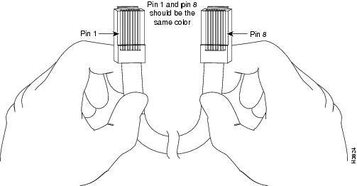
A roll-over cable can be detected by comparing the two modular ends of the cable. Holding the cables in your hand, side-by-side, with the tab at the back, the wire connected to the pin on the outside of the left plug should be the same color as the pin on the outside of the right plug. If your cable was purchased from Cisco, pin 1 will be white on one connector, and pin 8 will be white on the other (a roll-over cable reverses pins 1 and 8, 2 and 7, 3 and 6, and 4 and 5). (See Figure 5-12.)
Figure 5-12 Identifying a Roll-Over Cable
The Cisco 7200 series routers ship with a roll-over cable. Connection to a terminal or a modem requires an RJ-45-to-DB-25 adapter, and possibly a DB-25-to-DB9 adapter. Refer to Table 5-10 for the cable and adapter configurations that can be used to connect terminals and modems to the Cisco 7200 series routers.
|
|
|
|
|
|---|---|---|---|
Console or auxiliary |
Roll-over |
FDTE1 |
Terminal |
Console or auxiliary |
Straight |
FDCE |
Terminal |
Auxiliary or console |
Roll-over |
MMOD2 |
Modem |
1 The FDTE RJ-45-to-DB-25 adapter is labeled "Terminal". 2 The MMOD RJ-45-to-DB-25 adapter is labeled "Modem". |
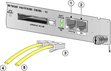
The cable and auxiliary ports are configured as asynchronous serial ports. Figure 5-13 shows the RJ-45 console and auxiliary port connections.
Figure 5-13 Console and Auxiliary Port RJ-45 Connections
|
|
Console port |
|
Cable to console terminal or DTE |
|
|
Auxiliary port |
|
Cable to modem or DCE |
|
|
RJ-45 connectors |
A cable and adapter kit is available from Cisco (Product Number ACS-2500ASYN=). Table 5-10 describes the cable and adapter configurations that can be used to connect terminals and modems to the console or the auxiliary port.
RJ-45 Console Port Signals and Pinouts
The NPE-G1 console port supports Data Carrier Detect (DCD). Table 5-11 lists the RJ-45 console port signals for the NPE-G1.
|
|
|
|
|
|---|---|---|---|
1 |
CTS |
Out |
Clear To Send (tracks RTS) |
2 |
DSR |
Out |
Data Set Ready (always on) |
3 |
RXD |
Out |
Receive Data |
4 |
GND |
— |
Signal Ground |
6 |
TXD |
In |
Transmit Data |
7 |
DTR |
In |
Data Terminal Ready |
8 |
RTS |
In |
Ready To Send |
1 Any pin not referenced is not connected. |
RJ-45 Auxiliary Port Signals and Pinouts
Table 5-12 lists the RJ-45 auxiliary port signals for the NPE-G1.
|
|
|
|
|
|---|---|---|---|
1 |
RTS |
Out |
Ready To Send |
2 |
DTR |
Out |
Data Terminal Ready |
3 |
TXD |
Out |
Transmit Data |
4 |
RING2 |
In |
Ring Indication |
5 |
GND |
— |
Signal Ground |
6 |
RXD |
In |
Receive Data |
73 |
DSR/DCD(RLSD) |
In |
Data Set Ready/Data Carrier Detect (Receive Line Signal Detect) |
8 |
CTS |
In |
Clear To Send (tracks RTS) |
1 Any pin not referenced is not connected. 2 RING is not supported on Cisco-supplied adapters. To use this pin, you must create a customized cable. 3 Pin 7 can be used as a DCD input for connection to a modem. The RJ-45-to-DB-25F adapter maps DCD to this pin when used with a straight-through cable. |
Fiber Optic Cleaning Information
We strongly recommend cleaning all optical fiber connections before reconnecting optical cables to equipment. For information about cleaning optical connectors, see the Inspection and Cleaning Procedures for Fiber-Optic Connections document and the Compressed Air Cleaning Issues for Fiber-Optic Connections document.
 Feedback