- Preface
- NPE-100, NPE-150, and NPE-200 Overview
- NPE-175 and NPE-225 Overview
- NPE-300 and NPE-400 Overview
- NSE-1 Overview
- NPE-G1 Overview
- NPE-G2 Overview
- NPE-G1 and NPE-G2 Installation and Configuration Information
- Preparation for Installation
- Removing and Installing the NPE or NSE
- Configuration Tasks and Troubleshooting Information
Network Processing Engine and Network Services Engine Installation and Configuration
Bias-Free Language
The documentation set for this product strives to use bias-free language. For the purposes of this documentation set, bias-free is defined as language that does not imply discrimination based on age, disability, gender, racial identity, ethnic identity, sexual orientation, socioeconomic status, and intersectionality. Exceptions may be present in the documentation due to language that is hardcoded in the user interfaces of the product software, language used based on RFP documentation, or language that is used by a referenced third-party product. Learn more about how Cisco is using Inclusive Language.
- Updated:
- September 7, 2009
Chapter: Removing and Installing the NPE or NSE
- Ensuring Easy Access to the Router
- Removing and Replacing the NPE or NSE
- Powering Down the Router and Disconnecting Input Power
- Powering Down the Router
- Disconnecting AC-Input Power from a Cisco 7200 Series Router or Cisco 7200 VXR Router
- Disconnecting AC-Input Power from a Cisco uBR7200 Series Router
- Disconnecting DC-Input Power from a Cisco 7200 Series Router or Cisco 7200 VXR Router
- Disconnecting DC-Input Power from a Cisco uBR7246 Router
- Removing the NPE or NSE
- Removing and Installing Memory
- Installing the NPE or NSE
- Reconnecting Input Power and Powering Up the Router
- Reconnecting AC-Input Power to the Cisco 7200 Series Router or Cisco 7200 VXR Router
- Reconnecting AC-Input Power to the Cisco uBR7200 Series Router
- Reconnecting DC-Input Power to a Cisco 7200 Series Router or Cisco 7200 VXR Router
- Reconnecting DC-Input Power to a Cisco uBR7246VXR Router
- Powering Up the Router
- Powering Down the Router and Disconnecting Input Power
Removing and Installing the NPE or NSE
This chapter describes how to remove a network processing engine (NPE) or network services engine (NSE) from supported platforms and also how to install a replacement network processing engine or network services engine. This chapter provides instructions for the NPE-100 through NPE-400 and the NSE-1. The NPE-G1 and NPE-G2 installation instructions are in Chapter 7, "Installing the NPE-G1 or NPE-G2.". This chapter contains the following sections:
•![]() Ensuring Easy Access to the Router
Ensuring Easy Access to the Router
•![]() Removing and Replacing the NPE or NSE
Removing and Replacing the NPE or NSE

Note ![]() This chapter describes the installation of all processors except the NPE-G1, the NPE-G2, and the Cisco uBR7200-NPE-G1. For those processors, please see Chapter 7, "NPE-G1 and NPE-G2 Installation and Configuration Information."
This chapter describes the installation of all processors except the NPE-G1, the NPE-G2, and the Cisco uBR7200-NPE-G1. For those processors, please see Chapter 7, "NPE-G1 and NPE-G2 Installation and Configuration Information."
Ensuring Easy Access to the Router
If your Cisco 7200 VXR router or Cisco uBR7246VXR router is installed in a standard 19-inch, 4-post or telco-type rack, cables from other equipment in the rack might obstruct access to the rear of the router. Also, rack power strips or other permanent fixtures may obstruct access to the router. Review the following guidelines to ensure easy access to the rear of the router when it is installed in a rack. If the router is not installed in a rack, or if you already have clear access to the rear of the router, proceed to the "Removing and Replacing the NPE or NSE" section.
Use the following guidelines to ensure easy access to the rear of the router when it is installed in a rack:
•![]() Ensure that you have at least 3 to 4 feet (0.91 to 1.22 meters) of working space at the rear of the router.
Ensure that you have at least 3 to 4 feet (0.91 to 1.22 meters) of working space at the rear of the router.
•![]() If cables from other equipment in the rack fall in front of the rear end of the router, carefully gather the cables (using care not to strain or stress them) and use cable ties to anchor them away from the rear of the router.
If cables from other equipment in the rack fall in front of the rear end of the router, carefully gather the cables (using care not to strain or stress them) and use cable ties to anchor them away from the rear of the router.
•![]() If access to the rear of the router is partially blocked by a power strip or some other permanent rack fixture, detach the router from the rack and carefully slide it forward until there is enough clearance to remove the power supply, the network processing engine, and the subchassis from the router. Detailed steps for detaching the router from the rack are contained in the "Removing and Replacing the NPE or NSE" section.
If access to the rear of the router is partially blocked by a power strip or some other permanent rack fixture, detach the router from the rack and carefully slide it forward until there is enough clearance to remove the power supply, the network processing engine, and the subchassis from the router. Detailed steps for detaching the router from the rack are contained in the "Removing and Replacing the NPE or NSE" section.

Removing and Replacing the NPE or NSE
The procedures for removing and replacing an NPE or NSE are the same for all Cisco 7200 series routers, including the Cisco 7206 and Cisco 7206VXR when used as router shelves in the Cisco AS5800 Universal Access Server. The procedures are also the same for the Cisco uBR7246VXR router.
The illustrations and procedures in the following sections apply to the Cisco 7200 series routers or Cisco uBR7246VXR router and the Cisco AS5800 Universal Access Server router shelves unless indicated otherwise.
Note ![]() The NSE-1 is keyed for insertion in only Cisco 7200 VXR routers. The NSE-1 is not supported on the Cisco uBR7246VXR universal broadband router, although it can be inserted into the router chassis.
The NSE-1 is keyed for insertion in only Cisco 7200 VXR routers. The NSE-1 is not supported on the Cisco uBR7246VXR universal broadband router, although it can be inserted into the router chassis.
The following sections explain how to remove and install an NPE or NSE-1 in the Cisco 7200 VXR routers or Cisco uBR7246VXR router:
•![]() Powering Down the Router and Disconnecting Input Power
Powering Down the Router and Disconnecting Input Power
•![]() Removing and Installing Memory
Removing and Installing Memory
•![]() Reconnecting Input Power and Powering Up the Router
Reconnecting Input Power and Powering Up the Router
Note ![]() When installing an NPE-175, NPE-225, NPE-300, NPE-400, or NSE-1 in a Cisco 7200 VXR router that is using a previously purchased I/O controller, you must upgrade the I/O controller boot helper image.
When installing an NPE-175, NPE-225, NPE-300, NPE-400, or NSE-1 in a Cisco 7200 VXR router that is using a previously purchased I/O controller, you must upgrade the I/O controller boot helper image.
Instructions for upgrading the boot helper image on the I/O controller are contained in the online Memory Replacement Instructions for the Network Processing Engine or Network Services Engine and Input/Output Controller publication.
Powering Down the Router and Disconnecting Input Power
Complete the steps in the following sections to power down the router and disconnect input power.

Warning ![]() This unit might have more than one power cord. To reduce the risk of electric shock, disconnect the two power cords before servicing. Statement 83
This unit might have more than one power cord. To reduce the risk of electric shock, disconnect the two power cords before servicing. Statement 83
Powering Down the Router
To power down a Cisco 7200 series router, Cisco 7204VXR or Cisco 7206VXR router, or Cisco uBR7200 series router, complete the following steps:
Note ![]() Before powering down the router, use the copy running-config startup-config command to save the router's running configuration to nonvolatile memory.
Before powering down the router, use the copy running-config startup-config command to save the router's running configuration to nonvolatile memory.
Step 1 ![]() Facing the rear of the router, place the power switch on the power supply in the off (O) position. Repeat this action if a second power supply is installed in the router.
Facing the rear of the router, place the power switch on the power supply in the off (O) position. Repeat this action if a second power supply is installed in the router.
Note ![]() When powering off the router, wait a minimum of 30 seconds before powering it on again.
When powering off the router, wait a minimum of 30 seconds before powering it on again.
Step 2 ![]() Observe the following items:
Observe the following items:
•![]() The green OK LED on the power supply turns off.
The green OK LED on the power supply turns off.
•![]() The fans stop operating.
The fans stop operating.
•![]() The LEDs on the I/O controller turn off.
The LEDs on the I/O controller turn off.
•![]() The LEDs on the port adapters turn off.
The LEDs on the port adapters turn off.
•![]() On a Cisco uBR7200 series router, the LEDs on the cable interface line cards turn off.
On a Cisco uBR7200 series router, the LEDs on the cable interface line cards turn off.
This completes the procedure for powering down the router. For instructions on disconnecting power from the Cisco 7200 series routers, Cisco 7200 VXR routers, or Cisco uBR7200 routers, see the following sections:
•![]() Disconnecting AC-Input Power from a Cisco 7200 Series Router or Cisco 7200 VXR Router
Disconnecting AC-Input Power from a Cisco 7200 Series Router or Cisco 7200 VXR Router
•![]() Disconnecting AC-Input Power from a Cisco uBR7200 Series Router
Disconnecting AC-Input Power from a Cisco uBR7200 Series Router
•![]() Disconnecting DC-Input Power from a Cisco 7200 Series Router or Cisco 7200 VXR Router
Disconnecting DC-Input Power from a Cisco 7200 Series Router or Cisco 7200 VXR Router
•![]() Disconnecting DC-Input Power from a Cisco uBR7246 Router
Disconnecting DC-Input Power from a Cisco uBR7246 Router
Disconnecting AC-Input Power from a Cisco 7200 Series Router or Cisco 7200 VXR Router
To disconnect AC-input power from a Cisco 7200 series router or Cisco 7200 VXR router, complete the following steps:
Step 1 ![]() Unplug the input power cable from the power source.
Unplug the input power cable from the power source.
Step 2 ![]() Push up on the cable-retention clip that secures the input power cable to the router power supply.
Push up on the cable-retention clip that secures the input power cable to the router power supply.
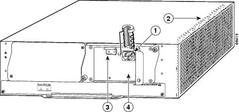
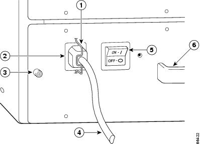
Step 3 ![]() Unplug the other end of the input power cable from the power supply. See Figure 9-1.
Unplug the other end of the input power cable from the power supply. See Figure 9-1.
Figure 9-1 Disconnecting Power from a Cisco 7200 Series AC-Input Power Supply
|
|
AC-input receptacle |
|
Power switch |
|
|
Internal fans |
|
AC-input power supply |
Step 4 ![]() Repeat Step 1 through Step 3 if a second power supply is installed.
Repeat Step 1 through Step 3 if a second power supply is installed.
This completes the procedure for disconnecting AC-input power from a Cisco 7200 series router or Cisco 7200 VXR router. Go to the "Removing the NPE or NSE" section.
Disconnecting AC-Input Power from a Cisco uBR7200 Series Router
To disconnect AC-input power from a Cisco uBR7200 series router, complete the following steps:
Step 1 ![]() Unplug the input power cable from the power source.
Unplug the input power cable from the power source.
Step 2 ![]() Push the cable-retention clip that secures the input power cable to the router power supply to the left.
Push the cable-retention clip that secures the input power cable to the router power supply to the left.
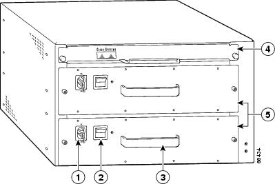
Step 3 ![]() Unplug the other end of the input power cable from the power supply. See Figure 9-2.
Unplug the other end of the input power cable from the power supply. See Figure 9-2.
Figure 9-2 Disconnecting Power from a Cisco uBR7200 Series AC-Input Power Supply—Cisco uBR7246 Shown
|
|
AC-input receptacle |
|
Network processing engine |
|
|
Power switch |
|
AC-input power supply |
|
|
Handle |
Step 4 ![]() Repeat Step 1 through Step 3 if a second power supply is installed.
Repeat Step 1 through Step 3 if a second power supply is installed.
This completes the procedure for disconnecting AC-input power from a Cisco uBR7200 series router. Go to the "Removing the NPE or NSE" section.
Disconnecting DC-Input Power from a Cisco 7200 Series Router or Cisco 7200 VXR Router
To disconnect DC-input power from a Cisco 7200 series router or Cisco 7200 VXR router, complete the following steps.
Warning ![]() Before completing any of the following procedures, and to prevent short-circuit or shock hazards, ensure that power is removed from the DC circuit. To ensure that all power is OFF, locate the circuit breaker on the panel board that services the DC circuit, switch the circuit breaker to the OFF position, and tape the switch handle of the circuit breaker in the OFF position. Statement 322
Before completing any of the following procedures, and to prevent short-circuit or shock hazards, ensure that power is removed from the DC circuit. To ensure that all power is OFF, locate the circuit breaker on the panel board that services the DC circuit, switch the circuit breaker to the OFF position, and tape the switch handle of the circuit breaker in the OFF position. Statement 322
Warning ![]() When you install the unit, the ground connection must always be made first and disconnected last. Statement 42
When you install the unit, the ground connection must always be made first and disconnected last. Statement 42
Step 1 ![]() At the rear of the router, check that the power switch on the power supply is in the off (O) position.
At the rear of the router, check that the power switch on the power supply is in the off (O) position.
Step 2 ![]() Ensure that no current is running through the -V and +V leads. To ensure that all power is off, locate the circuit breaker on the panel board that services the DC circuit, switch the circuit breaker to the off position, and tape the switch handle of the circuit breaker in the off position.
Ensure that no current is running through the -V and +V leads. To ensure that all power is off, locate the circuit breaker on the panel board that services the DC circuit, switch the circuit breaker to the off position, and tape the switch handle of the circuit breaker in the off position.
Step 3 ![]() Remove the cable tie that secures the -V, +V, and ground leads to the power supply faceplate. Save the cable tie.
Remove the cable tie that secures the -V, +V, and ground leads to the power supply faceplate. Save the cable tie.
Note ![]() The cable tie that accompanied your Cisco 7200 series DC-input power supply can be removed and replaced on the power supply without the use of a tool. If you secured the DC-input power supply leads to the power supply faceplate using a different type of cable tie, use a wire stripper to cut that cable tie from the power supply.
The cable tie that accompanied your Cisco 7200 series DC-input power supply can be removed and replaced on the power supply without the use of a tool. If you secured the DC-input power supply leads to the power supply faceplate using a different type of cable tie, use a wire stripper to cut that cable tie from the power supply.
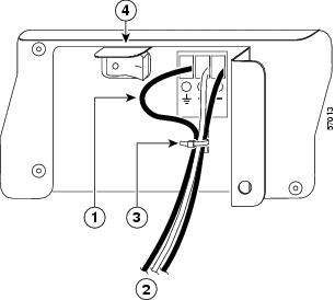
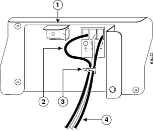
Step 4 ![]() Disconnect the -V and +V leads. You can leave the ground cable connected.
Disconnect the -V and +V leads. You can leave the ground cable connected.
Figure 9-3 Disconnecting DC-Input Power from a Cisco 7200 Series Router or Cisco 7200 VXR Router
|
|
Ground lead service loop |
|
Cable tie |
|
|
DC power leads |
|
Power switch |
Step 5 ![]() Using a 3/16-inch flat-blade screwdriver, loosen the screw below the +V lead receptacle and pull the lead from the connector. Repeat this step for the -V lead and the ground lead.
Using a 3/16-inch flat-blade screwdriver, loosen the screw below the +V lead receptacle and pull the lead from the connector. Repeat this step for the -V lead and the ground lead.
Note ![]() The color coding of the DC-input power supply leads depends on the color coding of the DC power source at your site. Typically, green or green and yellow are used for ground. Make certain that the lead color coding you choose for the DC-input power supply matches the lead color coding used at the DC power source.
The color coding of the DC-input power supply leads depends on the color coding of the DC power source at your site. Typically, green or green and yellow are used for ground. Make certain that the lead color coding you choose for the DC-input power supply matches the lead color coding used at the DC power source.
Step 6 ![]() Repeat Step 1 through Step 5 if a second power supply is installed.
Repeat Step 1 through Step 5 if a second power supply is installed.
This completes the procedure for disconnecting DC-input power from a Cisco 7200 series router or Cisco 7200 VXR router. Go to the "Removing the NPE or NSE" section.
Disconnecting DC-Input Power from a Cisco uBR7246 Router
To disconnect DC-input power from a Cisco uBR7346 router, complete the following steps.
Warning ![]() Before completing any of the following steps, and to prevent short-circuit or shock hazards, ensure that power is removed from the DC circuit. To ensure that all power is OFF, locate the circuit breaker on the panel board that services the DC circuit, switch the circuit breaker to the OFF position, and tape the switch handle of the circuit breaker in the OFF position. Statement 322
Before completing any of the following steps, and to prevent short-circuit or shock hazards, ensure that power is removed from the DC circuit. To ensure that all power is OFF, locate the circuit breaker on the panel board that services the DC circuit, switch the circuit breaker to the OFF position, and tape the switch handle of the circuit breaker in the OFF position. Statement 322
Warning ![]() When you install the unit, the ground connection must always be made first and disconnected last. Statement 42
When you install the unit, the ground connection must always be made first and disconnected last. Statement 42
Step 1 ![]() At the rear of the router, check that the power switch on the power supply is in the off (O) position.
At the rear of the router, check that the power switch on the power supply is in the off (O) position.
Step 2 ![]() Ensure that no current is running through the -V and +V leads. To ensure that all power is off, locate the circuit breaker on the panel board that services the DC circuit, switch the circuit breaker to the off position, and tape the switch handle of the circuit breaker in the off position.
Ensure that no current is running through the -V and +V leads. To ensure that all power is off, locate the circuit breaker on the panel board that services the DC circuit, switch the circuit breaker to the off position, and tape the switch handle of the circuit breaker in the off position.
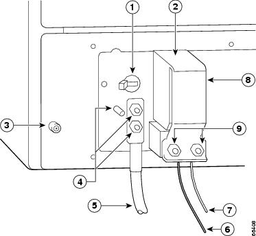
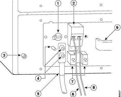
Step 3 ![]() Use a 7-mm wrench or nut driver (or adjustable wrench) to loosen and remove the two M4 nuts from the strain-relief cover that secures the -V and the +V leads to the power supply faceplate. See Figure 9-4.
Use a 7-mm wrench or nut driver (or adjustable wrench) to loosen and remove the two M4 nuts from the strain-relief cover that secures the -V and the +V leads to the power supply faceplate. See Figure 9-4.
Figure 9-4 Removing the Strain-Relief Cover from a Cisco uBR7246VXR Router DC-Input Power Supply
|
|
Power switch |
|
-V lead |
|
|
Power receptacle |
|
+V lead |
|
|
Captive installation screw |
|
Strain-relief cover |
|
|
M5 grounding receptacles |
|
M4 nuts |
|
|
M5 grounding lug |
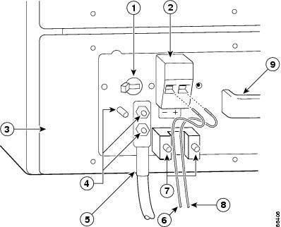
Step 4 ![]() Using a 3/16-inch flat-blade screwdriver, loosen the screw below the +V lead receptacle and pull the lead from the connector. Repeat this step for the -V lead only. See Figure 9-5.
Using a 3/16-inch flat-blade screwdriver, loosen the screw below the +V lead receptacle and pull the lead from the connector. Repeat this step for the -V lead only. See Figure 9-5.
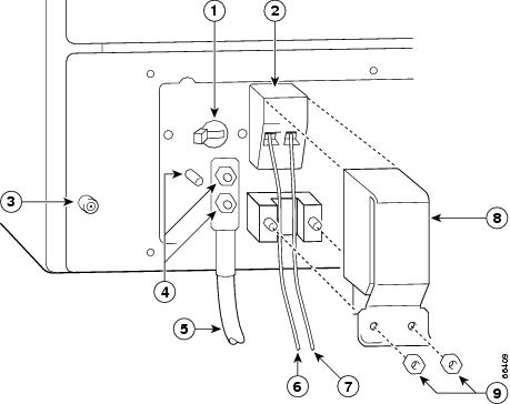
Figure 9-5 Disconnecting Power from a Cisco uBR7246VXR Router DC-Input Power Supply
|
|
Power switch |
|
-V lead |
|
|
Power receptacle |
|
M4 studs |
|
|
DC power supply |
|
+V lead |
|
|
M5 grounding receptacles |
|
Handle |
|
|
M5 grounding lug |
Step 5 ![]() Using an 8-mm wrench or nut driver (or adjustable wrench), loosen and remove the two M5 nuts that secure the two-hole grounding lug to the grounding receptacle, and pull the grounding lug and lead from the receptacle.
Using an 8-mm wrench or nut driver (or adjustable wrench), loosen and remove the two M5 nuts that secure the two-hole grounding lug to the grounding receptacle, and pull the grounding lug and lead from the receptacle.
Note ![]() The color coding of the DC-input power supply leads depends on the color coding of the DC power source at your site. Typically, green or green and yellow are used for ground. Make certain that the lead color coding you choose for the DC-input power supply matches the lead color coding used at the DC power source.
The color coding of the DC-input power supply leads depends on the color coding of the DC power source at your site. Typically, green or green and yellow are used for ground. Make certain that the lead color coding you choose for the DC-input power supply matches the lead color coding used at the DC power source.
Note ![]() Repeat the Steps 1 to 5 to disconnect secondary power supply, if connected.
Repeat the Steps 1 to 5 to disconnect secondary power supply, if connected.
This completes the procedure for disconnecting DC-input power from a Cisco uBR7246VXR router.
Go to the following section, "Removing the NPE or NSE".
Removing the NPE or NSE
To remove the NPE or NSE from a Cisco 7200 series router, Cisco 7204VXR or Cisco 7206VXR router, or Cisco uBR7200 series router, complete the following steps.
Note ![]() The weight of installed power supplies in your Cisco 7200 series router might make it difficult to remove the network processing engine. If you have difficulty, first remove the power supplies from the chassis, and then remove the network processing engine. See the "Removing and Replacing an AC-Input or DC-Input Power Supply" section on page 10-14 for information on removing and replacing an installed power supply.
The weight of installed power supplies in your Cisco 7200 series router might make it difficult to remove the network processing engine. If you have difficulty, first remove the power supplies from the chassis, and then remove the network processing engine. See the "Removing and Replacing an AC-Input or DC-Input Power Supply" section on page 10-14 for information on removing and replacing an installed power supply.
This note does not apply to the Cisco uBR7200 series routers; the network processing engine is installed above the power supplies in the Cisco uBR7200 series routers.
Note ![]() If you have difficulty installing a network processing engine or I/O controller in the lowest slot of a Cisco 7200 VXR router that is rack-mounted, remove the port adapters, network processing engine and I/O controller from the chassis and reinstall them. Install the network processing engine and I/O controller in the lowest slots first, then populate the slots above them, in a bottom-to-top order.
If you have difficulty installing a network processing engine or I/O controller in the lowest slot of a Cisco 7200 VXR router that is rack-mounted, remove the port adapters, network processing engine and I/O controller from the chassis and reinstall them. Install the network processing engine and I/O controller in the lowest slots first, then populate the slots above them, in a bottom-to-top order.
Step 1 ![]() Power down the router and disconnect the input power cable. (Refer to the "Powering Down the Router and Disconnecting Input Power" section.)
Power down the router and disconnect the input power cable. (Refer to the "Powering Down the Router and Disconnecting Input Power" section.)
Step 2 ![]() Attach an ESD-preventive wrist strap between you and an unfinished chassis surface.
Attach an ESD-preventive wrist strap between you and an unfinished chassis surface.
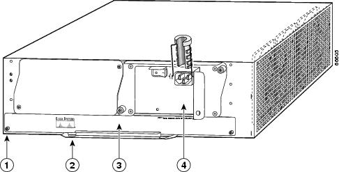
Step 3 ![]() Using a number 2 Phillips or a 3/16-inch flat-blade screwdriver, loosen the two captive installation screws on the faceplate of the network processing engine. (See Figure 9-6.)
Using a number 2 Phillips or a 3/16-inch flat-blade screwdriver, loosen the two captive installation screws on the faceplate of the network processing engine. (See Figure 9-6.)
If the router is not installed in a standard 19-inch, 4-post or telco-type rack, skip to Step 7. If the router is installed in a rack, determine if any permanent rack fixtures, such as a power strip, are obstructing access to the rear of the router. If a rack fixture is obstructing access to the router, proceed with Step 4.
Figure 9-6 Cisco 7200 Series NPE or NSE Captive Installation Screws and Handle
|
|
Captive installation screw |
|
Network processing engine or network services engine |
|
|
Handle |
|
AC-input power supply |
Step 4 ![]() Using a 3/16-inch flat-blade screwdriver, loosen the screws that secure the router to the front mounting strips of the rack.
Using a 3/16-inch flat-blade screwdriver, loosen the screws that secure the router to the front mounting strips of the rack.
Step 5 ![]() Position at least one person in front of the rack to support the front underside of the router.
Position at least one person in front of the rack to support the front underside of the router.
Step 6 ![]() From the rear of the rack, carefully push the front of the router out of the rack until there is enough clearance to remove the network processing engine.
From the rear of the rack, carefully push the front of the router out of the rack until there is enough clearance to remove the network processing engine.
Step 7 ![]() Grasp the network processing engine handle and carefully pull the network processing engine from its chassis slot.
Grasp the network processing engine handle and carefully pull the network processing engine from its chassis slot.
Step 8 ![]() Place the NPE or NSE on an antistatic surface with its printed circuit board components facing upward, or in a static shielding bag. If you are returning the network processing engine to the factory, immediately place it in a static shielding bag.
Place the NPE or NSE on an antistatic surface with its printed circuit board components facing upward, or in a static shielding bag. If you are returning the network processing engine to the factory, immediately place it in a static shielding bag.
This completes the procedure for removing an installed NPE or NSE. For instructions on installing the NPE or NSE, go to the "Installing the NPE or NSE" section.
Removing and Installing Memory
This section provides instructions for removing and installing DRAM or SDRAM on a network processing engine or network services engine.
Removing DRAM SIMMs
This section explains how to remove DRAM SIMMs that are installed on your network processing engine. To remove the installed DRAM SIMMs, complete the following steps:
Note ![]() The NPE-175, NPE-225, and NPE-300, and NSE-1 use SDRAM DIMMS. See the "Removing SDRAM DIMMs" section for DIMM replacement instructions.
The NPE-175, NPE-225, and NPE-300, and NSE-1 use SDRAM DIMMS. See the "Removing SDRAM DIMMs" section for DIMM replacement instructions.
Step 1 ![]() Attach an ESD-preventive wrist strap between you and an unpainted router surface.
Attach an ESD-preventive wrist strap between you and an unpainted router surface.
Step 2 ![]() Place the network processing engine on an antistatic mat or surface (ensure that you are wearing an antistatic device, such as a wrist strap).
Place the network processing engine on an antistatic mat or surface (ensure that you are wearing an antistatic device, such as a wrist strap).
Step 3 ![]() Position the network processing engine or network services engine so that the handle is away from you and the edge connector is toward you.
Position the network processing engine or network services engine so that the handle is away from you and the edge connector is toward you.
Step 4 ![]() Locate the SIMMs.
Locate the SIMMs.
For the location of the memory module you are replacing, find the illustration that corresponds to your network processing engine in Chapter 1, "NPE-100, NPE-150, and NPE-200 Overview."
Note ![]() SIMMs installed in your system might look different from the SIMMS shown in the following illustrations.
SIMMs installed in your system might look different from the SIMMS shown in the following illustrations.
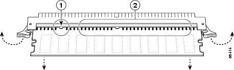
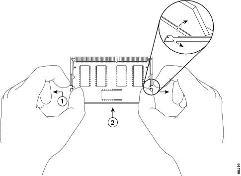
Step 5 ![]() Release the spring latches from the SIMM that you want to remove, and release the SIMM from the socket. (See Figure 9-7.)
Release the spring latches from the SIMM that you want to remove, and release the SIMM from the socket. (See Figure 9-7.)
a. ![]() Pull the latches away with your thumbs, bracing your forefingers against the posts.
Pull the latches away with your thumbs, bracing your forefingers against the posts.
b. ![]() Raise the SIMM to a vertical position.
Raise the SIMM to a vertical position.
Figure 9-7 Releasing the SIMM Spring Latches

|
|
Latch |
|
Faceplate edge of the system card |
|
|
Latch holes |
Step 6 ![]() When both ends of the SIMM are released from the socket, grasp the ends of the SIMM with your thumb and forefinger and pull the SIMM completely out of the socket. Handle the edges of the SIMM only; avoid touching the memory modules, pins, or traces (the metal fingers on the connector side of the SIMM).
When both ends of the SIMM are released from the socket, grasp the ends of the SIMM with your thumb and forefinger and pull the SIMM completely out of the socket. Handle the edges of the SIMM only; avoid touching the memory modules, pins, or traces (the metal fingers on the connector side of the SIMM).
Step 7 ![]() Place the SIMM in an antistatic bag to protect it from ESD damage. You can use the SIMMs that you remove in compatible equipment.
Place the SIMM in an antistatic bag to protect it from ESD damage. You can use the SIMMs that you remove in compatible equipment.
Step 8 ![]() Repeat Step 4 through Step 7 for the remaining SIMMs.
Repeat Step 4 through Step 7 for the remaining SIMMs.
This completes the SIMM removal procedure.
Installing DRAM SIMMs
The DRAM SIMMs on the network processing engine are located in the following sockets:
•![]() U18, U25, U4, and U12 on the NPE-100 and the NPE-150 (See Chapter 1, "NPE-100, NPE-150, and NPE-200 Overview," Figure 1-1 and Figure 1-2.)
U18, U25, U4, and U12 on the NPE-100 and the NPE-150 (See Chapter 1, "NPE-100, NPE-150, and NPE-200 Overview," Figure 1-1 and Figure 1-2.)
•![]() U11, U25, U42, and U52 on the NPE-200 (See Chapter 1, "NPE-100, NPE-150, and NPE-200 Overview," Figure 1-3.)
U11, U25, U42, and U52 on the NPE-200 (See Chapter 1, "NPE-100, NPE-150, and NPE-200 Overview," Figure 1-3.)
To install memory SIMMs in the network processing engine, complete the following steps:
Step 1 ![]() With the network processing engine in the same orientation as the previous procedure (with the handle away from you and the edge connector toward you), install the first SIMM in the socket farthest from you. Then install the last SIMM in the socket closest to you.
With the network processing engine in the same orientation as the previous procedure (with the handle away from you and the edge connector toward you), install the first SIMM in the socket farthest from you. Then install the last SIMM in the socket closest to you.
Step 2 ![]() Remove a new SIMM from the antistatic bag.
Remove a new SIMM from the antistatic bag.
Note ![]() To prevent DRAM errors in the NPE-100, NPE-150, or NPE-200, and to ensure that your system initializes correctly at startup, DRAM bank 0 (sockets U18 and U25, or U11 and U25) must contain no fewer than two SIMMs of the same type. You can also install two SIMMs of the same type in bank 1 (sockets U4 and U12, or U42 and U52); however, bank 0 must always contain the two largest SIMMs.
To prevent DRAM errors in the NPE-100, NPE-150, or NPE-200, and to ensure that your system initializes correctly at startup, DRAM bank 0 (sockets U18 and U25, or U11 and U25) must contain no fewer than two SIMMs of the same type. You can also install two SIMMs of the same type in bank 1 (sockets U4 and U12, or U42 and U52); however, bank 0 must always contain the two largest SIMMs.
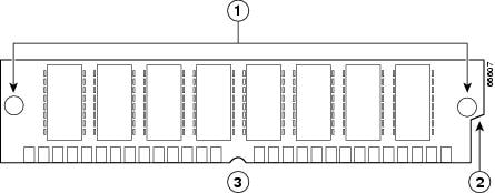
Figure 9-8 Cisco 7200 Series Main Memory SIMM
|
|
Alignment holes |
|
Connector edge with notch |
|
|
Polarization notch |
Step 3 ![]() Orient the SIMM so its connector edge (the metal fingers) is down and the component side is facing you. (See Figure 9-8.)
Orient the SIMM so its connector edge (the metal fingers) is down and the component side is facing you. (See Figure 9-8.)
Step 4 ![]() Hold the sides of the SIMM between your thumb and middle finger, with your forefinger against the far edge, opposite the connector edge.
Hold the sides of the SIMM between your thumb and middle finger, with your forefinger against the far edge, opposite the connector edge.
Step 5 ![]() Tilt the SIMM to approximately the same angle as the socket and insert the entire connector edge into the socket.
Tilt the SIMM to approximately the same angle as the socket and insert the entire connector edge into the socket.
Step 6 ![]() Gently push the SIMM into the socket until the spring latches snap over the ends of the SIMM. If necessary, rock the SIMM gently back and forth to seat it properly.
Gently push the SIMM into the socket until the spring latches snap over the ends of the SIMM. If necessary, rock the SIMM gently back and forth to seat it properly.
Step 7 ![]() Repeat Step 2 through Step 6 for the remaining SIMMs.
Repeat Step 2 through Step 6 for the remaining SIMMs.
Step 8 ![]() When all SIMMs are installed, check all alignment holes (two on each SIMM) and ensure that the spring latch is visible. If it is not, the SIMM is not seated properly. If any SIMM appears misaligned, carefully remove it and reseat it in the socket. Push the SIMM firmly back into the socket until the spring latches snap into place.
When all SIMMs are installed, check all alignment holes (two on each SIMM) and ensure that the spring latch is visible. If it is not, the SIMM is not seated properly. If any SIMM appears misaligned, carefully remove it and reseat it in the socket. Push the SIMM firmly back into the socket until the spring latches snap into place.
This completes the SIMM replacement procedure. Proceed to the "Installing the NPE or NSE" section.
Removing SDRAM DIMMs
The procedures in this section are required only if you have an NPE-175, NPE-225, NPE-300, or NSE-1 and need to upgrade or replace the SDRAM DIMMs. On the NPE-175, NPE-225, and NSE-1, the SDRAM DIMMs are located in socket U15. The two user-configurable SDRAM DIMMs on the NPE-300 are located in sockets U45 and U44.
Note ![]() The NPE-300 contains two banks of SDRAM. Both SDRAM banks are used for all packet memory requirements; however, bank 0 is used exclusively for packet memory and is set at a fixed configuration in the factory.
The NPE-300 contains two banks of SDRAM. Both SDRAM banks are used for all packet memory requirements; however, bank 0 is used exclusively for packet memory and is set at a fixed configuration in the factory.
Bank 1 contains two user-configurable SDRAM slots, DIMM slot 2 and DIMM slot 3 (see Chapter 3, "NPE-300 and NPE-400 Overview," the "Components" section on page 3-2). Both slots in bank 1 can be populated by DIMMs of different sizes; however, the size of the DIMM in slot 2 must be greater than or equal to the size of the DIMM in slot 3, and the size of the DIMM in slot 3 can be zero.
Note ![]() Use only SDRAM DIMMs supplied by Cisco.
Use only SDRAM DIMMs supplied by Cisco.
Use the following procedure to remove the existing DIMMs:
Step 1 ![]() Turn off the system power and remove the network processing engine or network services engine from the system. (Follow the steps in the "Removing the NPE or NSE" section.)
Turn off the system power and remove the network processing engine or network services engine from the system. (Follow the steps in the "Removing the NPE or NSE" section.)
Step 2 ![]() Place the network processing engine or network services engine on an antistatic mat or pad and ensure that you are wearing an antistatic device, such as a wrist strap.
Place the network processing engine or network services engine on an antistatic mat or pad and ensure that you are wearing an antistatic device, such as a wrist strap.
Step 3 ![]() Locate the DIMM and position the network processing engine or network services engine so that you are facing the DIMM you want to remove.
Locate the DIMM and position the network processing engine or network services engine so that you are facing the DIMM you want to remove.
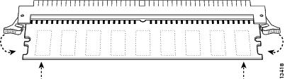
Step 4 ![]() Open the DIMM socket latches on the DIMM to release the DIMM from the socket. (See Figure 9-9.) The DIMM is under tension in the socket; therefore, the DIMM might be released from the socket with some force.
Open the DIMM socket latches on the DIMM to release the DIMM from the socket. (See Figure 9-9.) The DIMM is under tension in the socket; therefore, the DIMM might be released from the socket with some force.
Figure 9-9 Opening DIMM Socket Latches
|
|
Release latches |
|
SDRAM DIMM |
Note ![]() The SDRAM DIMM sockets on the NPE-175, NPE-225, and NPE-300 are parallel to the circuit board. They are not tilted at an angle.
The SDRAM DIMM sockets on the NPE-175, NPE-225, and NPE-300 are parallel to the circuit board. They are not tilted at an angle.
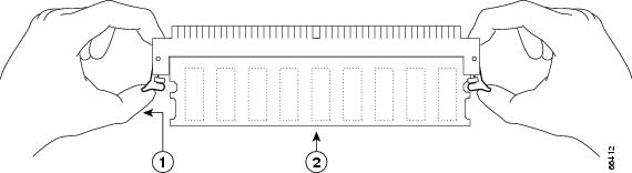
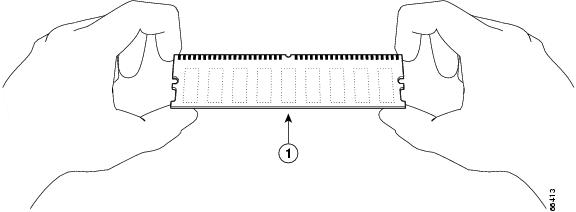
Step 5 ![]() With the DIMM socket latches open, grasp the ends of the DIMM between your thumbs and forefingers and pull the DIMM completely out of the socket. (See Figure 9-10.)
With the DIMM socket latches open, grasp the ends of the DIMM between your thumbs and forefingers and pull the DIMM completely out of the socket. (See Figure 9-10.)
Figure 9-10 Removing the DIMM
|
|
Notch |
|
Metal fingers |
Handle the edges of the DIMM only; avoid touching the memory modules, pin or traces (the metal fingers on the connector side of the DIMM). (See Figure 9-11.)
Figure 9-11 Handling the DIMM
|
|
SDRAM DIMM |
Step 6 ![]() Place the DIMM in an antistatic container to protect it from ESD damage.
Place the DIMM in an antistatic container to protect it from ESD damage.
This completes the DIMM removal procedure. Go to the "Installing SDRAM DIMMs" section.
Installing SDRAM DIMMs
Note ![]() The NPE-300 contains two banks of SDRAM. Both SDRAM banks are used for all packet memory requirements; however, bank 0 is used exclusively for packet memory and is set at a fixed configuration in the factory.
The NPE-300 contains two banks of SDRAM. Both SDRAM banks are used for all packet memory requirements; however, bank 0 is used exclusively for packet memory and is set at a fixed configuration in the factory.
Bank 1 contains two user-configurable SDRAM slots, DIMM slot 2 and DIMM slot 3. (See Chapter 3, "NPE-300 and NPE-400 Overview," the "Components" section on page 3-2.) Both slots in bank 1 can be populated by DIMMs of different sizes; however, the size of the DIMM in slot 2 must be greater than or equal to the size of the DIMM in slot 3, and the size of the DIMM in slot 3 can be zero.
With the network processing engine or network services engine in the same orientation as the previous procedure, install the DIMM in the DIMM socket as follows:
Step 1 ![]() Remove the new DIMM from its antistatic container.
Remove the new DIMM from its antistatic container.
Step 2 ![]() Hold the DIMM between your thumbs and forefingers. (See Figure 9-11.)
Hold the DIMM between your thumbs and forefingers. (See Figure 9-11.)
Note ![]() The 64-MB DIMM should be facing component-side-down.
The 64-MB DIMM should be facing component-side-down.
Step 3 ![]() Align the notch on the DIMM with the connector. The DIMM only inserts one way.
Align the notch on the DIMM with the connector. The DIMM only inserts one way.
Step 4 ![]() Insert the edge of the DIMM into the socket.
Insert the edge of the DIMM into the socket.
Note ![]() The SDRAM DIMM sockets on the NPE-175, NPE-225, and NPE-300 are parallel to the circuit board. They are not tilted at an angle.
The SDRAM DIMM sockets on the NPE-175, NPE-225, and NPE-300 are parallel to the circuit board. They are not tilted at an angle.
Step 5 ![]() Gently push the DIMM into the socket until the socket latches close over the ends of the DIMM. (See Figure 9-12.) If necessary, rock the DIMM gently back and forth to seat it properly.
Gently push the DIMM into the socket until the socket latches close over the ends of the DIMM. (See Figure 9-12.) If necessary, rock the DIMM gently back and forth to seat it properly.
Figure 9-12 Inserting the DIMM
Step 6 ![]() When the DIMM is installed, check to see it is seated properly. If the DIMM appears misaligned, carefully remove it and reseat it in the socket. Push the DIMM firmly back into the socket until first one and then the other socket latch moves into place.
When the DIMM is installed, check to see it is seated properly. If the DIMM appears misaligned, carefully remove it and reseat it in the socket. Push the DIMM firmly back into the socket until first one and then the other socket latch moves into place.
Step 7 ![]() Repeat Step 4 and Step 5 if you are replacing more than one DIMM.
Repeat Step 4 and Step 5 if you are replacing more than one DIMM.
This completes the DIMM replacement procedure. Go to the "Installing the NPE or NSE" section.
Removing a SDRAM SODIMM
This section provides a procedure for removing the small outline dual in-line memory module (SODIMM) on the NPE-400.
Follow these steps to remove the existing SODIMM:
Step 1 ![]() Remove the NPE-400 from the system.
Remove the NPE-400 from the system.
Step 2 ![]() Place the NPE-400 on an antistatic mat or pad and ensure that you are wearing an antistatic device, such as a wrist strap.
Place the NPE-400 on an antistatic mat or pad and ensure that you are wearing an antistatic device, such as a wrist strap.
Step 3 ![]() Locate the SODIMM (see Figure 9-13).
Locate the SODIMM (see Figure 9-13).
Figure 9-13 Location of SDRAM SODIMM on the NPE-400
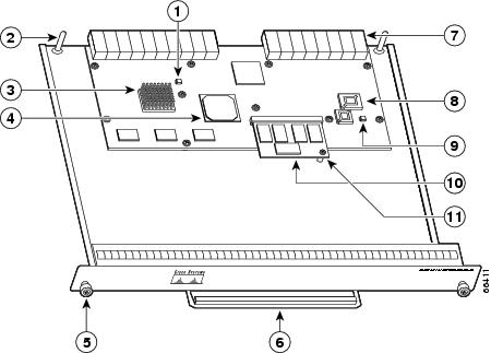
Step 4 ![]() Locate the SODIMM standoff screw and use a Phillips screwdriver to remove it.
Locate the SODIMM standoff screw and use a Phillips screwdriver to remove it.
Figure 9-14 Releasing the SODIMM Spring Latch
|
|
Spring latch on the release latch |
|
SDRAM SODIMM |
Step 5 ![]() Remove the SODIMM you want to replace by pulling outward on the SODIMM spring latches with your thumbs.
Remove the SODIMM you want to replace by pulling outward on the SODIMM spring latches with your thumbs.
The SODIMM springs up to allow you to easily pull it from the socket.
Step 6 ![]() Remove the SODIMM from the socket. Avoid touching the SODIMM as much as possible, particularly the traces, the metal fingers on the connector side of the SODIMM.
Remove the SODIMM from the socket. Avoid touching the SODIMM as much as possible, particularly the traces, the metal fingers on the connector side of the SODIMM.
Step 7 ![]() Place the SODIMM in an antistatic container to protect it from ESD damage.
Place the SODIMM in an antistatic container to protect it from ESD damage.
This completes the SODIMM removal procedure. Proceed to the next section to install the new SODIMM.
Installing a SDRAM SODIMM
This section provides a procedure for replacing the SODIMM on the NPE-400.
The synchronous dynamic random-access memory (SDRAM) on the NPE-400 is contained in one small outline dual in-line memory module (SODIMM) (see Figure 9-13).
Figure 9-15 Handling a SODIMM
Follow these steps to install the new SODIMM:
Step 1 ![]() Remove a new SODIMM from the antistatic container.
Remove a new SODIMM from the antistatic container.
Step 2 ![]() Hold the SODIMM component-side-up, with the connector edge (the metal fingers) away from you.
Hold the SODIMM component-side-up, with the connector edge (the metal fingers) away from you.
Step 3 ![]() Tilt the SODIMM to approximately the same angle as the socket, and insert the connector edge into the socket.
Tilt the SODIMM to approximately the same angle as the socket, and insert the connector edge into the socket.
Step 4 ![]() Gently press on the SODIMM until the SODIMM spring latches snap into place.
Gently press on the SODIMM until the SODIMM spring latches snap into place.
Step 5 ![]() If the SODIMM appears misaligned, carefully remove it and reseat it in the socket. Push the SODIMM gently back into the socket until the spring latches snap into place.
If the SODIMM appears misaligned, carefully remove it and reseat it in the socket. Push the SODIMM gently back into the socket until the spring latches snap into place.
This completes the SDRAM SODIMM replacement procedure. To reinstall the NPE-400 in the chassis, see the "Installing the NPE or NSE" section.
Checking a SDRAM Upgrade or Replacement
If, after a SDRAM upgrade or replacement, the system fails to boot properly, or if the console terminal displays a checksum or memory error, ensure that the SIMM, DIMM, or SODIMM is installed correctly. If necessary, shut down the system and remove the network processing engine or network services engine. Check the SIMM, DIMM, or SODIMM by looking straight down it and then at eye level. The SIMMs or DIMMs should be aligned at the same angle and the same height as others on the board when properly installed. If the SIMM, DIMM, or SODIMM appears to stick out or rest in the socket at an odd angle, remove it and reinsert it. Then replace the network processing engine or network services engine and reboot the system for another installation check.
If after several attempts the system fails to restart properly, contact a service representative for assistance. Before you call, note any error messages, unusual LED states, or other indications that might help solve the problem.
Installing the NPE or NSE
Note ![]() If you have difficulty installing a network processing engine or I/O controller in the lowest slot of a Cisco 7200 VXR router that is rack-mounted, remove the port adapters, network processing engine and I/O controller from the chassis and reinstall them. Install the network processing engine and I/O controller in the lowest slots first, then populate the slots above them, in a bottom-to-top order.
If you have difficulty installing a network processing engine or I/O controller in the lowest slot of a Cisco 7200 VXR router that is rack-mounted, remove the port adapters, network processing engine and I/O controller from the chassis and reinstall them. Install the network processing engine and I/O controller in the lowest slots first, then populate the slots above them, in a bottom-to-top order.
To install an NPE or NSE in the router, complete the following steps:
Note ![]() When installing an NPE-175, NPE-225, NPE-300, NPE-400, or NSE-1 in a Cisco 7200 VXR router that is using a previously purchased I/O controller, you must upgrade the I/O controller boot helper image.
When installing an NPE-175, NPE-225, NPE-300, NPE-400, or NSE-1 in a Cisco 7200 VXR router that is using a previously purchased I/O controller, you must upgrade the I/O controller boot helper image.
Instructions for upgrading the boot helper image on the I/O controller are contained in the online Memory Replacement Instructions for the Network Processing Engine or Network Services Engine and Input/Output Controller publication.
Step 1 ![]() Ensure that the router is powered down and the input power cable is disconnected from the router and the power source. See the "Powering Down the Router and Disconnecting Input Power" section.
Ensure that the router is powered down and the input power cable is disconnected from the router and the power source. See the "Powering Down the Router and Disconnecting Input Power" section.
Step 2 ![]() Attach an ESD-preventive wrist strap between you and an unfinished chassis surface.
Attach an ESD-preventive wrist strap between you and an unfinished chassis surface.
Step 3 ![]() Remove the new network processing engine or network services engine from its static shielding bag.
Remove the new network processing engine or network services engine from its static shielding bag.
Step 4 ![]() Using both hands, grasp the NPE or NSE by its metal carrier edges and orient it so that its printed circuit board components are upward. (See Figure 9-16.)
Using both hands, grasp the NPE or NSE by its metal carrier edges and orient it so that its printed circuit board components are upward. (See Figure 9-16.)
Step 5 ![]() Align the left and right edges of the network processing engine or network services engine printed circuit board between the network processing engine slot guides.
Align the left and right edges of the network processing engine or network services engine printed circuit board between the network processing engine slot guides.
Note ![]() For the NPE-175 and NPE-225, align the left and right edges of the network processing engine metal carrier into the guides.
For the NPE-175 and NPE-225, align the left and right edges of the network processing engine metal carrier into the guides.
Note ![]() The NPE-300 and NPE-400 are compatible only with the Cisco 7200 VXR router and Cisco uBR7246VXR router; the NPE-300 and NPE-400 are keyed to prevent insertion in the Cisco 7200 series routers (7202, 7204, and 7206) and Cisco uBR7200 series routers (Cisco uBR7223 and Cisco uBR7246).
The NPE-300 and NPE-400 are compatible only with the Cisco 7200 VXR router and Cisco uBR7246VXR router; the NPE-300 and NPE-400 are keyed to prevent insertion in the Cisco 7200 series routers (7202, 7204, and 7206) and Cisco uBR7200 series routers (Cisco uBR7223 and Cisco uBR7246).
Note ![]() The NSE-1 is compatible with the Cisco 7200 VXR routers only. It is keyed to prevent insertion in the Cisco 7200 series routers and the Cisco uBR7200 series routers.
The NSE-1 is compatible with the Cisco 7200 VXR routers only. It is keyed to prevent insertion in the Cisco 7200 series routers and the Cisco uBR7200 series routers.
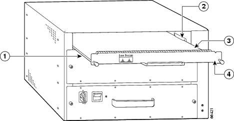
Figure 9-16 Aligning the NPE Between the Slot Guides on a Cisco 7200 VXR Router
|
|
Slot guides |
|
Printed circuit board |
|
|
Network processing engine or network services engine |
|
Metal carrier |
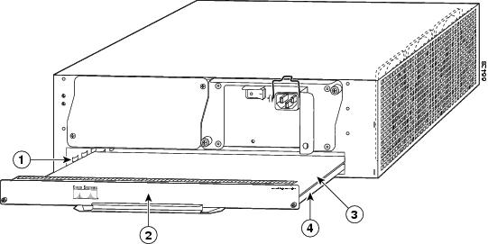
Figure 9-17 Aligning the NPE Between the Slot Guides on a Cisco uBR7200 Series—Cisco uBR7246 Shown
|
|
Metal carrier |
|
Printed circuit board |
|
|
Slot guides |
|
Network processing engine |
Step 6 ![]() Gently slide the network processing engine all the way into its chassis slot until you feel the connectors seat with the router midplane.
Gently slide the network processing engine all the way into its chassis slot until you feel the connectors seat with the router midplane.
Step 7 ![]() Seat the network processing engine in the router midplane by tightening its captive installation screws with a number 2 Phillips or a 3/16-inch flat-blade screwdriver.
Seat the network processing engine in the router midplane by tightening its captive installation screws with a number 2 Phillips or a 3/16-inch flat-blade screwdriver.
Note ![]() The network processing engine is not fully seated in the router midplane until you tighten its captive installation screws.
The network processing engine is not fully seated in the router midplane until you tighten its captive installation screws.
Step 8 ![]() If you removed power supplies from the router, replace the power supplies. (See the "Removing and Replacing an AC-Input or DC-Input Power Supply" section on page 10-14 when replacing a power supply in a Cisco 7200 series router.)
If you removed power supplies from the router, replace the power supplies. (See the "Removing and Replacing an AC-Input or DC-Input Power Supply" section on page 10-14 when replacing a power supply in a Cisco 7200 series router.)
Step 9 ![]() If you slid the front of the router out of the rack, slowly guide the router back into the rack.
If you slid the front of the router out of the rack, slowly guide the router back into the rack.
Step 10 ![]() Use a 3/16-inch flat-blade screwdriver to tighten the screws that secure the router to the front mounting strips of the rack.
Use a 3/16-inch flat-blade screwdriver to tighten the screws that secure the router to the front mounting strips of the rack.
This completes the procedure for replacing the network processing engine in a Cisco 7200 series router or Cisco uBR7200 series router.
Reconnecting Input Power and Powering Up the Router
The following procedures explain how to reconnect input power to a Cisco 7200 series router, Cisco 7200 VXR router, and Cisco uBR7200 series router, power up the router, and verify a successful system boot.
Warning ![]() Read the installation instructions before you connect the system to its power source. Statement 10
Read the installation instructions before you connect the system to its power source. Statement 10
Note ![]() When installing an NPE-175, NPE-225, NPE-300, NPE-400, or NSE-1 in a Cisco 7200 VXR router that is using a previously purchased I/O controller, you must upgrade the I/O controller boot helper image.
When installing an NPE-175, NPE-225, NPE-300, NPE-400, or NSE-1 in a Cisco 7200 VXR router that is using a previously purchased I/O controller, you must upgrade the I/O controller boot helper image.
Instructions for upgrading the boot helper image on the I/O controller are contained in the online Memory Replacement Instructions for the Network Processing Engine or Network Services Engine and Input/Output Controller publication.
To reconnect AC-input power or DC-input power to a Cisco 7200 series router, Cisco 7200 VXR router, or Cisco uBR7200 series router, see these sections:
•![]() Reconnecting AC-Input Power to the Cisco 7200 Series Router or Cisco 7200 VXR Router
Reconnecting AC-Input Power to the Cisco 7200 Series Router or Cisco 7200 VXR Router
•![]() Reconnecting AC-Input Power to the Cisco uBR7200 Series Router
Reconnecting AC-Input Power to the Cisco uBR7200 Series Router
•![]() Reconnecting DC-Input Power to a Cisco 7200 Series Router or Cisco 7200 VXR Router
Reconnecting DC-Input Power to a Cisco 7200 Series Router or Cisco 7200 VXR Router
•![]() Reconnecting DC-Input Power to a Cisco uBR7246VXR Router
Reconnecting DC-Input Power to a Cisco uBR7246VXR Router
Reconnecting AC-Input Power to the Cisco 7200 Series Router or Cisco 7200 VXR Router
To reconnect AC-input power to a Cisco 7200 series router or Cisco 7200 VXR router, complete the following steps:
Step 1 ![]() At the rear of the router, check that the power switch on the power supply is in the off (O) position.
At the rear of the router, check that the power switch on the power supply is in the off (O) position.
Figure 9-18 Connecting AC-Input Power to a Cisco 7200 Series Router

|
|
Power switch |
|
Cable-retention clip |
|
|
AC power cable |
|
Handle with hole for nylon cable tie |
|
|
POWER OK LED |
Step 2 ![]() Slide the cable-retention clip up away from the AC receptacle, and plug in the power cable.
Slide the cable-retention clip up away from the AC receptacle, and plug in the power cable.
Step 3 ![]() Secure the cable in the power supply AC receptacle by sliding the cable-retention clip down until it snaps around the connector. The cable-retention clip provides strain relief for the AC power cable.
Secure the cable in the power supply AC receptacle by sliding the cable-retention clip down until it snaps around the connector. The cable-retention clip provides strain relief for the AC power cable.
Step 4 ![]() Plug the AC power supply cable into the AC power source.
Plug the AC power supply cable into the AC power source.
Note ![]() For the Cisco 7200 series routers, each AC-input power supply operating at 120 VAC requires a minimum of 5A service.
For the Cisco 7200 series routers, each AC-input power supply operating at 120 VAC requires a minimum of 5A service.
We recommend powering the Cisco 7200 series routers from a 120 VAC, 15A receptacle U.S. (240 VAC, 10A international) at the power source.
Step 5 ![]() Repeat Step 1 through Step 4 if a second power supply is installed.
Repeat Step 1 through Step 4 if a second power supply is installed.
This completes the steps for reconnecting AC-input power to a Cisco 7200 series router or Cisco 7200 VXR router. Proceed to the "Powering Up the Router" section.
Reconnecting AC-Input Power to the Cisco uBR7200 Series Router
Figure 9-19 Connecting AC-Input Power to a Cisco uBR7200 Series Router
|
|
Cable-retention clip |
|
AC power cable |
|
|
Power receptacle |
|
Power switch |
|
|
Captive installation screw |
|
Handle |
To reconnect AC-input power to the Cisco uBR7200 series router complete, the following steps:
Step 1 ![]() At the rear of the router, check that the power switch on the power supply is in the off (O) position.
At the rear of the router, check that the power switch on the power supply is in the off (O) position.
Step 2 ![]() Slide the cable-retention clip to the left away from the AC receptacle, and plug in the power cable.
Slide the cable-retention clip to the left away from the AC receptacle, and plug in the power cable.
Step 3 ![]() Secure the cable in the power supply AC receptacle by sliding the cable-retention clip to the right until it snaps around the connector. The cable-retention clip provides strain relief for the AC power cable.
Secure the cable in the power supply AC receptacle by sliding the cable-retention clip to the right until it snaps around the connector. The cable-retention clip provides strain relief for the AC power cable.
Step 4 ![]() Plug the AC power supply cable into the AC power source.
Plug the AC power supply cable into the AC power source.
Note ![]() For the Cisco uBR7200 series routers, each AC-input power supply operating at 120 VAC requires a minimum of 7A service.
For the Cisco uBR7200 series routers, each AC-input power supply operating at 120 VAC requires a minimum of 7A service.
We recommend powering the Cisco uBR7200 series routers from a 120 VAC, 15A receptacle U.S. (240 VAC, 10A international) at the power source.
Step 5 ![]() Repeat Step 1 through Step 4 if a second power supply is installed.
Repeat Step 1 through Step 4 if a second power supply is installed.
This completes the steps for reconnecting AC-input power to a Cisco uBR7200 series router. Proceed to the "Powering Up the Router" section.
Reconnecting DC-Input Power to a Cisco 7200 Series Router or Cisco 7200 VXR Router
To reconnect DC-input power to a Cisco 7200 series router or Cisco 7200 VXR router, complete the following steps:
Note ![]() The color coding of the DC-input power supply leads depends on the color coding of the DC power source at your site. Typically, green or green and yellow are used for ground. Make certain that the lead color coding you choose for the DC-input power supply matches the lead color coding used at the DC power source.
The color coding of the DC-input power supply leads depends on the color coding of the DC power source at your site. Typically, green or green and yellow are used for ground. Make certain that the lead color coding you choose for the DC-input power supply matches the lead color coding used at the DC power source.
Warning ![]() Before completing any of the following steps, and to prevent short-circuit or shock hazards, ensure that power is removed from the DC circuit. To ensure that all power is OFF, locate the circuit breaker on the panel board that services the DC circuit, switch the circuit breaker to the OFF position, and tape the switch handle of the circuit breaker in the OFF position. Statement 322
Before completing any of the following steps, and to prevent short-circuit or shock hazards, ensure that power is removed from the DC circuit. To ensure that all power is OFF, locate the circuit breaker on the panel board that services the DC circuit, switch the circuit breaker to the OFF position, and tape the switch handle of the circuit breaker in the OFF position. Statement 322
Warning ![]() When installing the unit, the ground connection must always be made first and disconnected last. Statement 42
When installing the unit, the ground connection must always be made first and disconnected last. Statement 42
Step 1 ![]() At the rear of the router, check that the power switch on the power supply is in the off (O) position.
At the rear of the router, check that the power switch on the power supply is in the off (O) position.
Step 2 ![]() Ensure that no current is running through the -V and +V leads. To ensure that all power is off, locate the circuit breaker on the panel board that services the DC circuit, switch the circuit breaker to the off position, and tape the switch handle of the circuit breaker in the off position.
Ensure that no current is running through the -V and +V leads. To ensure that all power is off, locate the circuit breaker on the panel board that services the DC circuit, switch the circuit breaker to the off position, and tape the switch handle of the circuit breaker in the off position.
Figure 9-20 Connecting DC-Input Power to a Cisco 7200 Series Router
|
|
Power switch |
|
Cable tie |
|
|
Ground lead service loop |
|
DC power leads |
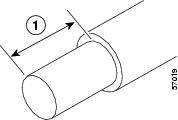
Step 3 ![]() If necessary, use a wire stripper to strip approximately 0.55 inch (14 mm) from the -V, +V, and ground leads. (See Step 3.)
If necessary, use a wire stripper to strip approximately 0.55 inch (14 mm) from the -V, +V, and ground leads. (See Step 3.)
Figure 9-21 Stripping the DC-Input Lines
|
|
0.55 in. (14 mm) |
Step 4 ![]() Insert the stripped end of the ground lead all the way into the ground lead receptacle on the DC-input power supply and tighten the receptacle screw using a 3/16-inch flat-blade screwdriver.
Insert the stripped end of the ground lead all the way into the ground lead receptacle on the DC-input power supply and tighten the receptacle screw using a 3/16-inch flat-blade screwdriver.
Step 5 ![]() Insert the stripped end of the +V lead all the way into the +V lead receptacle and tighten the receptacle screw using the same 3/16-inch flat-blade screwdriver. Repeat this step for the -V lead.
Insert the stripped end of the +V lead all the way into the +V lead receptacle and tighten the receptacle screw using the same 3/16-inch flat-blade screwdriver. Repeat this step for the -V lead.
Note ![]() Make sure that the entire stripped end of each lead is inserted all the way into its receptacle. If any exposed wire at the stripped end of a lead is visible after inserting the lead into its receptacle, remove the lead from the receptacle, use the wire stripper to cut the stripped end of the lead, and repeat through Step 5.
Make sure that the entire stripped end of each lead is inserted all the way into its receptacle. If any exposed wire at the stripped end of a lead is visible after inserting the lead into its receptacle, remove the lead from the receptacle, use the wire stripper to cut the stripped end of the lead, and repeat through Step 5.
Step 6 ![]() After tightening the receptacle screws for the ground, +V, and -V DC-input leads, secure the leads to the power supply faceplate.
After tightening the receptacle screws for the ground, +V, and -V DC-input leads, secure the leads to the power supply faceplate.
Use the cable tie you saved earlier in this procedure to secure the three leads.
Note ![]() When securing the ground, +V, and -V DC-input leads to the power supply faceplate, leave a small service loop in the ground lead to ensure that it is the last lead to disconnect from the power supply if a great deal of strain is placed on all three leads. (See Figure 9-20.)
When securing the ground, +V, and -V DC-input leads to the power supply faceplate, leave a small service loop in the ground lead to ensure that it is the last lead to disconnect from the power supply if a great deal of strain is placed on all three leads. (See Figure 9-20.)
Step 7 ![]() Restore current to the -V and +V leads.
Restore current to the -V and +V leads.
Note ![]() For the Cisco 7200 series routers:
For the Cisco 7200 series routers:
- Each DC-input power supply operating at 24 VDC requires a minimum of 19A service.
- Each DC-input power supply operating at 48 VDC requires a minimum of 13A service.
- Each DC-input power supply operating at 60 VDC requires a minimum of 8A service.
This product relies on the building's installation for short-circuit (overcurrent) protection. Ensure that a listed and certified fuse or circuit breaker, 35A minimum 60 VDC, is used on all current-carrying conductors. Site wiring and circuit breakers need to be sized to accommodate the maximum values for safety reasons.
Step 8 ![]() Repeat Step 1 through Step 7 if a second power supply is installed.
Repeat Step 1 through Step 7 if a second power supply is installed.
This completes the steps for reconnecting DC-input power to a Cisco 7200 series router or a Cisco 7200 VXR router. Proceed to the "Powering Up the Router" section.
Reconnecting DC-Input Power to a Cisco uBR7246VXR Router
To reconnect DC-input power to a Cisco uBR7246VXR router, complete the following steps:
Note ![]() The color coding of the DC-input power supply leads depends on the color coding of the DC power source at your site. Typically, green or green and yellow are used for ground. Make certain that the lead color coding you choose for the DC-input power supply matches the lead color coding used at the DC power source.
The color coding of the DC-input power supply leads depends on the color coding of the DC power source at your site. Typically, green or green and yellow are used for ground. Make certain that the lead color coding you choose for the DC-input power supply matches the lead color coding used at the DC power source.
Warning ![]() Before completing any of the following steps, and to prevent short-circuit or shock hazards, ensure that power is removed from the DC circuit. To ensure that all power is OFF, locate the circuit breaker on the panel board that services the DC circuit, switch the circuit breaker to the OFF position, and tape the switch handle of the circuit breaker in the OFF position. Statement 322
Before completing any of the following steps, and to prevent short-circuit or shock hazards, ensure that power is removed from the DC circuit. To ensure that all power is OFF, locate the circuit breaker on the panel board that services the DC circuit, switch the circuit breaker to the OFF position, and tape the switch handle of the circuit breaker in the OFF position. Statement 322
Warning ![]() When installing the unit, the ground connection must always be made first and disconnected last. Statement 42
When installing the unit, the ground connection must always be made first and disconnected last. Statement 42
Step 1 ![]() At the rear of the router, check that the power switch on the power supply is in the off (O) position.
At the rear of the router, check that the power switch on the power supply is in the off (O) position.
Step 2 ![]() Ensure that no current is running through the -V and +V leads. To ensure that all power is off , locate the circuit breaker on the panel board that services the DC circuit, switch the circuit breaker to the off position, and tape the switch handle of the circuit breaker in the off position.
Ensure that no current is running through the -V and +V leads. To ensure that all power is off , locate the circuit breaker on the panel board that services the DC circuit, switch the circuit breaker to the off position, and tape the switch handle of the circuit breaker in the off position.
Figure 9-22 Connecting DC-Input Power to a Cisco uBR7246VXR Router
|
|
Power switch |
|
-V lead |
|
|
Power receptacle |
|
M4 studs |
|
|
Captive installation screw |
|
+V lead |
|
|
M5 grounding receptacles |
|
Handle |
|
|
M5 grounding lug |
Step 3 ![]() If necessary, use a wire stripper to strip approximately 0.55 inch (14 mm) from the -V, +V, and ground leads.
If necessary, use a wire stripper to strip approximately 0.55 inch (14 mm) from the -V, +V, and ground leads.
Note ![]() The ground lead for the Cisco uBR7246VXR router DC-input power supply consists of a two-hole grounding lug that connects to an M5 grounding receptacle; you do not need to strip this ground lead.
The ground lead for the Cisco uBR7246VXR router DC-input power supply consists of a two-hole grounding lug that connects to an M5 grounding receptacle; you do not need to strip this ground lead.
Figure 9-23 Stripping the DC-Input Lines
|
|
0.55 in. (14 mm) |
Step 4 ![]() Connect the two-hole grounding lug on the grounding lead to the M5 grounding receptacles with the M5 nuts. Tighten the nuts using an 8-mm wrench or nut driver (or adjustable wrench). (See Figure 9-24.)
Connect the two-hole grounding lug on the grounding lead to the M5 grounding receptacles with the M5 nuts. Tighten the nuts using an 8-mm wrench or nut driver (or adjustable wrench). (See Figure 9-24.)
Step 5 ![]() Insert the stripped end of the +V lead all the way into the +V lead receptacle and tighten the receptacle screw using the 3/16-inch flat-blade screwdriver. Repeat this step for the -V lead.
Insert the stripped end of the +V lead all the way into the +V lead receptacle and tighten the receptacle screw using the 3/16-inch flat-blade screwdriver. Repeat this step for the -V lead.
Note ![]() Make sure that the entire stripped end of each lead is inserted all the way into its receptacle. If any exposed wire at the stripped end of a lead is visible after inserting the lead into its receptacle, remove the lead from the receptacle, use the wire stripper to cut the stripped end of the lead, and repeat through Step 5.
Make sure that the entire stripped end of each lead is inserted all the way into its receptacle. If any exposed wire at the stripped end of a lead is visible after inserting the lead into its receptacle, remove the lead from the receptacle, use the wire stripper to cut the stripped end of the lead, and repeat through Step 5.
Step 6 ![]() After tightening the receptacle screw or nuts for the ground, +V, and -V DC-input leads, secure the leads to the power supply faceplate.
After tightening the receptacle screw or nuts for the ground, +V, and -V DC-input leads, secure the leads to the power supply faceplate.
Step 7 ![]() Run the +V and -V leads between the two strain-relief studs on the power supply faceplate.
Run the +V and -V leads between the two strain-relief studs on the power supply faceplate.
Note ![]() A service loop is not required in the lead attached to the grounding lug because this lead is separate from the +V and -V leads and is secured by two M5 nuts to the M5 receptacles.
A service loop is not required in the lead attached to the grounding lug because this lead is separate from the +V and -V leads and is secured by two M5 nuts to the M5 receptacles.
Step 8 ![]() Replace the strain-relief cover over the +V and -V leads and secure the cover to the strain-relief studs with the two M4 nuts using the 7-mm wrench or nut driver (or adjustable wrench).
Replace the strain-relief cover over the +V and -V leads and secure the cover to the strain-relief studs with the two M4 nuts using the 7-mm wrench or nut driver (or adjustable wrench).
Figure 9-24 Replacing the Strain-Relief Cover on a Cisco uBR7246VXR Router DC-Input Power Supply
|
|
Power switch |
|
-V lead |
|
|
Power receptacle |
|
+V lead |
|
|
Captive installation screw |
|
Strain-relief cover |
|
|
M5 grounding receptacles |
|
M4 nuts |
|
|
M5 grounding lug |
Step 9 ![]() Restore current to the -V and +V leads.
Restore current to the -V and +V leads.
Note ![]() For the Cisco uBR7246VXR router, each DC-input power supply rating is 14A, 700 volt ampere (VA).
For the Cisco uBR7246VXR router, each DC-input power supply rating is 14A, 700 volt ampere (VA).
This product relies on the building's installation for short-circuit (overcurrent) protection. Ensure that a listed and certified fuse or circuit breaker, 35A minimum 60 VDC, is used on all current-carrying conductors. Site wiring and circuit breakers need to be sized to accommodate the maximum values for safety reasons.
Step 10 ![]() Repeat Step 1 through Step 9 if a second power supply is installed.
Repeat Step 1 through Step 9 if a second power supply is installed.
This completes the steps for reconnecting DC-input power to a Cisco uBR7246VXR router. Proceed to the following section, "Powering Up the Router."
Powering Up the Router
To power up a Cisco 7200 series router, Cisco 7200 VXR router, or Cisco uBR7200 series router that has an installed power supply, complete the following steps:
Step 1 ![]() Check for the following:
Check for the following:
–![]() Each port adapter is inserted in its slot, and its respective port adapter lever is in the locked position.
Each port adapter is inserted in its slot, and its respective port adapter lever is in the locked position.
–![]() The network processing engine and the I/O controller are inserted in their respective slots, and the captive installation screws are tightened.
The network processing engine and the I/O controller are inserted in their respective slots, and the captive installation screws are tightened.
–![]() All network interface cables are connected to the port adapters.
All network interface cables are connected to the port adapters.
–![]() Each cable interface line card is inserted in its slot, and its respective captive installation screws are tightened (Cisco uBR7200 series router only).
Each cable interface line card is inserted in its slot, and its respective captive installation screws are tightened (Cisco uBR7200 series router only).
–![]() A PC Card or Flash Disk is installed in one of the PC Card slots.
A PC Card or Flash Disk is installed in one of the PC Card slots.
Note ![]() The Flash Disk can be installed in either slot 0 or slot 1 of the Cisco 7200 series router.
The Flash Disk can be installed in either slot 0 or slot 1 of the Cisco 7200 series router.
–![]() Each AC-input power cable is connected and secured with the cable-retention clip (AC-input power supplies only).
Each AC-input power cable is connected and secured with the cable-retention clip (AC-input power supplies only).
–![]() For a Cisco 7200 series router, each DC lead is connected and secured to the power supply faceplate with a cable tie.
For a Cisco 7200 series router, each DC lead is connected and secured to the power supply faceplate with a cable tie.
–![]() For a Cisco uBR7200 series router, each DC lead is connected with M5 nuts for the grounding receptacle and the strain-relief cover over the +V and -V leads (DC-input power supplies only).
For a Cisco uBR7200 series router, each DC lead is connected with M5 nuts for the grounding receptacle and the strain-relief cover over the +V and -V leads (DC-input power supplies only).
–![]() Each DC lead is connected and secured to the power source (DC-input power supplies only).
Each DC lead is connected and secured to the power source (DC-input power supplies only).
–![]() Ensure that the tape (that you applied earlier) is removed from the circuit breaker switch handle, and power is restored by moving the circuit breaker handle to the on (|) position (DC-input power supplies only).
Ensure that the tape (that you applied earlier) is removed from the circuit breaker switch handle, and power is restored by moving the circuit breaker handle to the on (|) position (DC-input power supplies only).
–![]() The console terminal is turned on.
The console terminal is turned on.
Step 2 ![]() At the rear of the router, place the power switch on the power supply in the on (|) position. Repeat this step if a second power supply is installed in the router. The green OK LED on the power supply turns on.
At the rear of the router, place the power switch on the power supply in the on (|) position. Repeat this step if a second power supply is installed in the router. The green OK LED on the power supply turns on.
Note ![]() When powering on the router, wait a minimum of 30 seconds before powering it off again.
When powering on the router, wait a minimum of 30 seconds before powering it off again.
Step 3 ![]() Listen for the fans; you should immediately hear them operating.
Listen for the fans; you should immediately hear them operating.
Step 4 ![]() During the boot process, observe the system LEDs. The LEDs on most of the port adapters go on and off in an irregular sequence. Some may go on, go out, and go on again for a short time. On the I/O controller, the I/O power OK LED goes on immediately.
During the boot process, observe the system LEDs. The LEDs on most of the port adapters go on and off in an irregular sequence. Some may go on, go out, and go on again for a short time. On the I/O controller, the I/O power OK LED goes on immediately.
Step 5 ![]() Observe the initialization process. When the system boot is complete (a few seconds), the network processing engine or network services engine begins to initialize the port adapters and the I/O controller. During this initialization, the LEDs on each port adapter behave differently (most flash on and off). The enabled LED on each port adapter and Cisco uBR7200 series cable interface line card goes on when initialization is completed, and the console screen displays a script and system banner similar to the following:
Observe the initialization process. When the system boot is complete (a few seconds), the network processing engine or network services engine begins to initialize the port adapters and the I/O controller. During this initialization, the LEDs on each port adapter behave differently (most flash on and off). The enabled LED on each port adapter and Cisco uBR7200 series cable interface line card goes on when initialization is completed, and the console screen displays a script and system banner similar to the following:
Cisco Internetwork Operating System Software
IOS (tm) 7200 Software (C7200-J-M), 11.3(2)T
Copyright (c) 1986-1998 by cisco Systems, Inc.
Compiled Sun 22-Feb-98 06:00 by Biff
This completes the procedures for connecting input power and powering up the router. This also completes the procedure for installing the network processing engine or network services engine in a Cisco 7200 series router, Cisco 7200 VXR router, or Cisco uBR7200 series router.
 Feedback