Cisco CRS-1 SPA
Interface Processor
This chapter describes the SPA interface processor (SIP) that is supported on the Cisco CRS-1 router and contains the following sections:
SIP Summary
A SIP is a type of PLIM that provides data interfaces for the routing system through the installed shared port adapters (SPAs). The SIP mates with its associated modular services card (MSC) through the chassis midplane. Each available SPA provides different interface types and port densities, as described in the chapter Overview: Cisco CRS Shared Port Adapters.
The below table shows a summary description of the SIP that is supported on the Cisco CRS-1 router.
 Note | The Description column indicates the aggregate bandwidth supported by the SIP across all subslots—not for each SPA subslot. |
|
SIP |
Product Number |
Description |
Maximum Number of SPAs |
Minimum Cisco IOS XR Software |
Minimum Hardware Revision |
|---|---|---|---|---|---|
|
Cisco CRS-1 SIP-800 |
CRS1-SIP-800 |
40-gigabit SPA interface processor |
6 single-width |
Release 3.2 |
1.0 |
Cisco CRS-1 SIP-800 Overview
The following sections describe the Cisco CRS-1 SIP-800:
LEDs
The Cisco CRS-1 SIP-800 has one LED, as shown in the figure below.
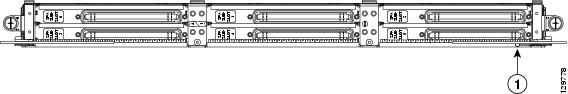
|
1 |
Status LED |
The table below describes the Cisco CRS-1 SIP-800 LED.
|
LED Label |
Color |
State |
Meaning |
|---|---|---|---|
|
— |
Green |
On |
The SIP is online and standing by. |
|
|
Amber |
On |
The SIP has failed and needs to be replaced. |
|
|
Off |
Off |
The SIP is offline and deactivated. |
Physical Specifications
The table below shows the Cisco CRS-1 SIP-800 physical specifications.
|
Description |
Specifications |
|---|---|
|
Physical dimensions(H x W x D) |
20.6 x 1.8 x 11.2 in. (52.32 x 4.57 x 28.4 cm)Occupies one physical layer interface module (PLIM) slot on the Cisco CRS-1 router |
|
Weight |
|
|
Shipping weight |
27 lb (12.25 kg) |
|
Operating temperature |
|
|
Storage temperature |
–40 to 158°F (–40 to 70°C) |
|
Relative humidity |
|
Identifying Slots and Subslots for SIPs and SPAs
The following sections describe SIP, SPA, and interface numbering:
- SIP Slot Locations on the Cisco CRS-1 Router
- SPA Slot Numbering on the Cisco CRS-1 SIP-800
- SPA Interface Addresses on SIPs
SIP Slot Locations on the Cisco CRS-1 Router
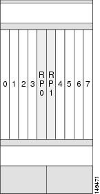
A SIP can be installed in PLIM slots 0 through 15 on the Cisco CRS-1 router 16-slot line card chassis and PLIM slots 0 through 7 on the Cisco CRS-1 router 8-slot line card chassis. Figure 2 and the figure below show the slot numbering on the front (PLIM side) of the line card chassis.
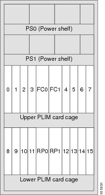
For additional information about the slot locations of PLIMs and their associated modular services cards (MSCs), see Cisco CRS Carrier Routing System 16-Slot Line Card Chassis System Description or Cisco CRS Carrier Routing System 8-Slot Line Card Chassis System Description . Both documents are available online from the specific chassis hardware documentation links at the following URL:
SPA Slot Numbering on the Cisco CRS-1 SIP-800
The Cisco CRS-1 SIP-800 accepts six single-width SPAs. The figure below shows a Cisco CRS-1 SIP-800 with two 4-Port OC-3c/STM-1 POS SPAs installed in subslots 0 and 3.
Note | Subslots 0, 1, and 3 can provide up to 20 Gbps of capacity, as can subslots 2, 4, and 5. Take care not to install SPAs that require more than 20 Gbps of capacity in each group of subslots so as not to oversubscribe the card. See the Bandwidth Oversubscription section in the Overview: Cisco CRS-1 Shared Port Adapters chapter for more information. |
The figure below and Figure 2 illustrate the SPA subslot locations on the Cisco CRS-1 SIP-800. The subslot labels are located inside the SPA subslot and are only visible when the SPA is not installed.
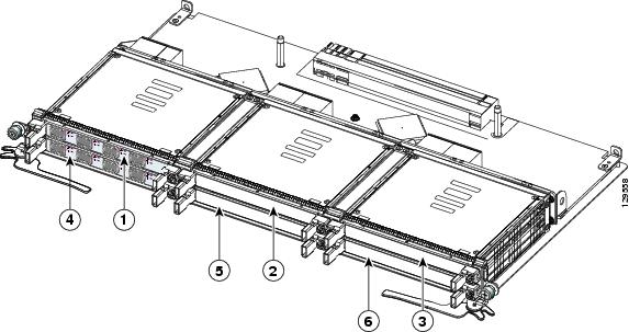
|
1 |
SPA subslot 0 |
4 |
SPA subslot 3 |
|
2 |
SPA subslot 1 |
5 |
SPA subslot 4 |
|
3 |
SPA subslot 2 |
6 |
SPA subslot 5 |
SPA Interface Addresses on SIPs
SPAs in the Cisco CRS-1 router running Cisco IOS XR Software Release 3.4.1 use an addressing format that specifies the physical location of the SIP, SPA, and interface. The interface address format is rack /slot /subslot /port , where:
- rack —Specifies the rack number, 0 in a single-chassis system.
-
slot
—Specifies the slot number in the Cisco CRS-1 router in which the SIP that contains the SPA is installed:
- For the 8-slot line card chassis—0 through 7
- For the 16-slot line card chassis—0 through 15
- subslot — Specifies the secondary slot on the SIP in which the SPA that you want to select is installed: for the Cisco CRS-1 SIP-800—0 through 5
-
port
—Specifies the interface number that you want to select on the SPA:
- For the 1-Port Clear Channel OC-3 ATM SPA—0 is the only option
- For the 3-Port Clear Channel OC-3 ATM SPA—0 through 2
- For the 1-Port Clear Channel OC-12 ATM SPA —0 is the only option
- For the 4-Port OC-3c/STM-1 POS SPA—0 through 3
- For the 8-Port OC-12c/STM-4 Multirate POS SPA—0 through 7
- For the 2-Port OC-48c/STM-16 POS/RPR SPA—0 through 1
- For the 4-Port OC-48c/STM-16 POS/RPR SPA—0 through 3
- For the 1-Port OC-192c/STM-64 POS/RPR XFP SPA—0 is the only option
- For the 1-Port OC-192c/STM-64 POS/RPR VSR Optics SPA—0 is the only option
- For the 5-Port Gigabit Ethernet SPA—0 through 4
- For the 8-Port Gigabit Ethernet SPA—0 through 7
- For the 10-Port Gigabit Ethernet SPA—0 through 9
- For the 1-Port 10-Gigabit Ethernet SPA—0 is the only option
- For the 2-Port Clear Channel T3/E3 SPA—0 through 1
- For the 4-Port Clear Channel T3/E3 SPA—0 through 3
 Feedback