Installing and
Removing a SIP
This chapter describes how to install or remove SIPs on the Cisco CRS-1 router. This chapter contains the following sections:
Handling SIPs
Each SIP is mounted to a metal carrier and is sensitive to electrostatic discharge (ESD) damage. Before you begin installation, read the Preparing to Install a SIP or a SPA. for a list of parts and tools required for installation.
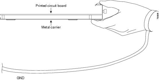
 Caution | Always handle the SIP by the carrier edges and handle; never touch the SIP components or connector pins (see the figure below). |
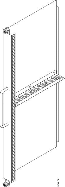
A PLIM impedance carrier must be installed in each empty PLIM slot in the Cisco CRS-1 router chassis (see see the figure below). The impedance carrier preserves the integrity of the chassis and is required for EMI compliance and proper cooling in the chassis.
Guidelines for SIP Installation and Removal
Guidelines for SIP installation and removal include the following:
- Online insertion and removal (OIR) is supported, enabling you to remove and install SIPs and SPAs while the router is running. OIR is seamless to users on the network, maintains all routing information, and ensures session preservation. Notifying the software or resetting the power is not required. However, you have the option of using the shutdown command before removing a card.
- Each SIP and its corresponding modular services card (MSC) function as a pair. If either card is removed, the other card is essentially powered down (although the router can still identify and inventory the cards).
- SIPs are attached to the chassis through a pair of ejector levers and captive screws. The two ejector levers are used to release the SIP from its midplane connector. The ejector levers and captive screws are located on the upper and bottom ends of the faceplate of the card (see the figure below).
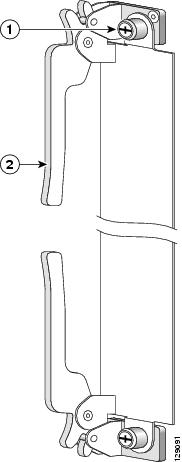
|
1 |
Captive screw |
2 |
Ejector lever |
Caution | When you remove a SIP, always use the ejector levers to ensure that the connector pins disconnect from the midplane in the sequence expected by the router. |
Caution | The router can indicate a hardware failure if you do not follow proper procedures. Remove or install only one SIP or PLIM at a time. Wait at least 15 seconds before removing or installing another SIP or PLIM. |
SIP Installation and Removal
This section contains the following procedures:
 Note | Refer to the Installing and Removing a SPA for information on removing and installing SPAs. |
Removing a SIP
To remove a SIP from the line card chassis, the figure below and follow these steps:
What to Do Next
1
Captive
screw
4
Guide
pins
2
Ejector
lever
5
Direction
of installation or removal
3
Septum

Installing a SIP
This section provides step-by-step instructions for installing a SIP. You can install a SIP in any slot not occupied by a Route Processor (RP) card (or a fan controller card on the 16-slot chassis only). If you install a new MSC or SIP, you must first remove the PLIM impedance carrier card from the available slot.
Caution | The system can indicate a hardware failure if you do not follow proper procedures. Remove or install only one SIP or PLIM at a time. Allow at least 15 seconds for the system to complete the preceding tasks before removing or installing another SIP or PLIM. |
During this procedure, wear grounding wrist straps to avoid ESD damage to the card. Do not directly touch the backplane with your hand or any metal tool, or you could shock yourself. Statement 94
To install a SIP, follow these steps:
| Step 1 | Attach an ESD-preventive wrist strap and follow its instructions for use. | ||||
| Step 2 | Remove the SIP from its antistatic packaging. | ||||
| Step 3 | Remove the PLIM
or PLIM impedance carrier from the slot you need to fill and set it aside.
| ||||
| Step 4 | Grasp one of the septums that separate the SPA slots or one of the ejector levers with one hand and place your other hand under the SIP to support and guide it into the correct slot. Slide the card halfway into the correct slot. Avoid touching the card circuitry or any connectors. | ||||
| Step 5 | Pivot both card
ejector levers so the openings on the card ejector cams at the top and bottom
of the SIP pass over the tabs on each side of the card cage slot.
| ||||
| Step 6 | Continue
sliding the SIP into the card cage slot until the openings on the card ejector
cams engage the tabs on each side of the card cage slot.
| ||||
| Step 7 | To seat the card in the midplane connector, grasp both card ejector levers and pivot them inward toward the handle in the card carrier until they are flush against the front edge of the card carrier. | ||||
| Step 8 | Engage both
captive screws on the PLIM, and then tighten the screws. Tighten the locking
thumbscrews on both sides of the SIP to a torque of between 8.3 and 11
inch-pounds (94 to 124 N-cm). Do not overtighten.
| ||||
| Step 9 | Install the SPAs. See the SPA Installation and Removal section. | ||||
| Step 10 | Install the interface cables. We recommend that you clean the fiber-optic connections before attaching the cables. See http://www.cisco.com/c/en/us/td/docs/routers/crs/maintenance/optics/maintenance/guide/crs_opt.html for cleaning instructions. | ||||
| Step 11 | If this SIP is
new, configure it for operation. For instructions, see
Cisco IOS XR
Interface and Hardware Component Configuration Guide for your software
release. For command syntax, refer to
Cisco IOS XR
Interface and Hardware Component Command Reference.
Because invisible radiation may be emitted from the aperture of the port when no fiber cable is connected, avoid exposure to radiation and do not stare into open apertures. Statement 125
|
 Feedback