Cisco CRS Carrier Routing System Multishelf System Description
Bias-Free Language
The documentation set for this product strives to use bias-free language. For the purposes of this documentation set, bias-free is defined as language that does not imply discrimination based on age, disability, gender, racial identity, ethnic identity, sexual orientation, socioeconomic status, and intersectionality. Exceptions may be present in the documentation due to language that is hardcoded in the user interfaces of the product software, language used based on RFP documentation, or language that is used by a referenced third-party product. Learn more about how Cisco is using Inclusive Language.
- Updated:
- December 1, 2016
Chapter: Optical Interface Modules and Optical Interface Module LED Card
Optical Interface Modules and Optical Interface Module LED Card
This chapter describes the optical interface module (OIM) cards and optical interface module light emitting diode (OIM-LED) cards. It includes these sections:
OIM Card Overview
OIM cards are used to connect the FCC and LCC together in a multishelf system, using a set of 24 optical array cables. Each OIM card (CRS-FCC-OIM-1S) has a set of 9 connectors and are located at the rear of the FCC. Each OIM is mated with one Fabric card in the front of the chassis via internal connectors.
Up to twenty-four OIM cards can be installed in the multishelf system FCCs. Depending on the number of FCCs used in your multishelf system configuration, you can have 2, 4, or 8 OIM cards per chassis.
The OIM is a passive device and provides fiber X-connect functions. The OIMs distribute the fibers within each fabric cable to the ASICs on the S2 SFCs.
 Note | This system description includes high-level details of the OIM and OIM-LED cards. These components are an integral part of the cabling and interconnection process that must be followed when configuring a multishelf system. See Cisco CRS Carrier Routing System Multishelf System Interconnection and Cabling Guide for complete information on the OIM cards, fabric cables, and OIM-LED cards. |
OIM Connectors
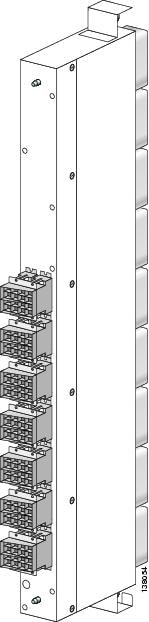
The OIM connectors on OIM cards are called bulkhead array adapters (BAAs). BAAs are used to terminate the fabric cables on the FCC side of a multishelf system. The other ends of the fabric cables are terminated on the fabric cards in the LCCs. See the Cisco CRS 16-slot LCC publications for details on the S13 SFCs. Below figure shows the BAAs on an OIM.

The connectors on the internal side of the OIM card are called high-density backplane mounted (HBMT) connectors, which provide a connection to the rear of the S2 SFCs within an FCC. Below figure shows the HBMT side of an OIM.
 Caution | Be careful while plugging the SFC to the HBMT connector. Excessive force may break the guide pins on the SFC and prevent successful connection of the SFC to the HBMT connector. |
Laser radiation. Do not view directly with optical instruments. Class 1M laser product. Statement 283
Each OIM mates with a corresponding S2 SFC within the FCC. See Cisco CRS Carrier Routing System Fabric Card Chassis Installation Guide for complete installation instructions and Cisco CRS Carrier Routing System Multishelf System Interconnection and Cabling Guide for complete cabling information.
OIM-LED Card Functional Overview
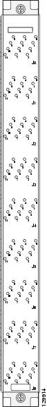
The OIM-LED card (CRS-FCC-LED) indicates the status of each fabric cable that connects a FCC to an LCC. The card gives visual indications of fabric cables that are operationally up or down, or incorrectly connected. It also specifies the correct place to connect or reconnect a fabric cable. Below figure shows the OIM-LED card.
OIM-LED Card Overview
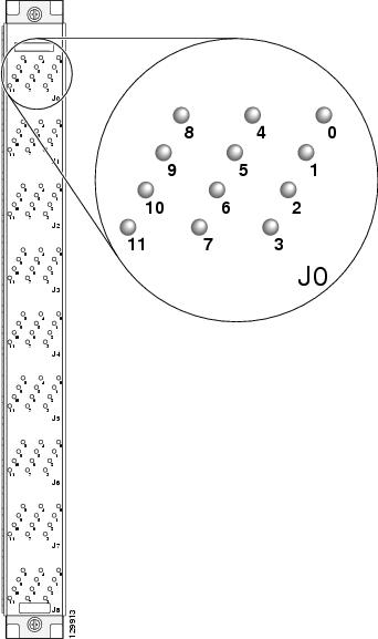
The OIM-LED card is used to facilitate cable installation and troubleshooting procedures. The status of a fabric cable is indicated through the various colors and states of the LED array. The below figure shows an exploded view of the LED indicators for each fabric cable.
This table shows the various LED states.
|
LED |
Description |
|---|---|
|
Off |
A card to which this fabric cable is attached is either powered off or not recognized within the chassis, or the fabric cable is not connected at one end of the connection. |
|
Green |
The fabric cable is properly connected at both ends and data transmission is occurring. |
|
Yellow |
The fabric cable is properly connected at both ends, although some data errors are occurring. |
|
Red |
More than one fabric cable is not connected to the correct location. |
|
Blinking red |
A single fabric cable is not connected to the correct location. |
|
Blinking green |
The location where the incorrectly connected fabric cable should be connected is shown. This LED corresponds to the blinking red LED described previously for cases in which a single fabric cable is connected incorrectly. |
Note | Because the OIM-LED card is present only in the FCC, the LEDs indicate the status of the fabric cables in just the FCC. When any connection is incorrect, it is assumed that the connection at the LCC end is correct and the connection at the FCC needs to be relocated to the correct position, as indicated by the LEDs. |
 Feedback