Cisco CRS Carrier Routing System Multishelf System Description
Bias-Free Language
The documentation set for this product strives to use bias-free language. For the purposes of this documentation set, bias-free is defined as language that does not imply discrimination based on age, disability, gender, racial identity, ethnic identity, sexual orientation, socioeconomic status, and intersectionality. Exceptions may be present in the documentation due to language that is hardcoded in the user interfaces of the product software, language used based on RFP documentation, or language that is used by a referenced third-party product. Learn more about how Cisco is using Inclusive Language.
- Updated:
- December 1, 2016
Chapter: Fabric Card Chassis Power System
Fabric Card Chassis Power System
This chapter describes the power system used in the fabric card chassis (FCC). It includes these sections:
Power specifications are provided in Specifications
- Power System Overview
- Power Component Information Common to the Two Types of Power Systems
- Fixed Configuration Power Supply
- Modular Configuration Power Supply
- Cisco CRS 3-Phase Power Distribution Unit
Power System Overview
The chassis power system provides power to chassis components and is made up of two power shelves that contain power modules. Each power shelf is connected to a separate and independent power source. Input power enters the power shelves and is processed by the power modules before being distributed to the components in the chassis.
The FCC can be either DC or AC powered. There are two options for power systems:
- The fixed configuration power system consists of two power shelves, AC rectifiers or DC power entry modules (PEMs), and alarm modules. The AC version requires either 3-phase AC-Delta or 3-phase AC-Wye input power to the power shelves. In a redundant configuration, the fixed configuration power system provides power sharing per load zone. The fixed configuration power system includes SNMP MIBS and XML support.
- The modular configuration power system consists of two power shelves, AC or DC power modules (PMs), and alarm modules. However, unlike the fixed configuration power system, the AC version of the modular configuration power system requires single-phase AC input power to the power shelves; there is no 3-phase AC-Wye or AC-Delta. If you have 3-phase AC Delta or AC Wye at your equipment, a Cisco CRS 3-phase AC power distribution unit (PDU) is required to convert 3-phase AC input power to single-phase AC input power for the power shelf. At the shelf level, the power system provides 2N redundancy; the PMs themselves provide load-share redundancy. The modular configuration power system also includes SNMP MIBS and XML support.
 Note | In a modular configuration AC power system, PDU refers to the Cisco CRS 3-phase AC PDU, which is required to convert 3-phase AC-Wye or AC-Delta input power to single-phase AC input power for the modular configuration AC power shelf. For further information, refer to the Cisco CRS 3-Phase AC Power Distribution Unit Installation Guide. |
Maximum input power requirements for the FCC with a fixed configuration power system installed are:
- DC-powered chassis requires up to a maximum of 9300 W (9.3 kW) of DC input power when the chassis is fully loaded.
- AC-powered chassis requires up to a maximum of 9800 W (9.8 kW) of AC input power when the chassis is fully loaded.
Maximum input power requirements for the FCC with a modular configuration power system installed are:
- DC-powered chassis requires up to a maximum of 14,300 watts (14.3 kW) of DC input power when the chassis is fully loaded.
- AC-powered chassis requires up to a maximum of 16,300 watts (16.3 kW) of AC input power when the chassis is fully loaded.
Note | If you have a Cisco CRS 3-phase AC PDU installed, six AC PMs are required to be installed in each modular configuration AC power shelf to maintain a balanced 3-phase power load. |
Power Component Information Common to the Two Types of Power Systems
This section introduces information shared by the fixed configuration power components and the modular configuration power components in these topics:
Basic Chassis Power Details
The FCC can be configured with either an AC-input power subsystem or a DC-input power subsystem. Site power requirements differ, depending on the source voltage used.
Follow these precautions and recommendations when planning power connections to the router:
- Check the power at your site before installation and periodically after installation to ensure that you are receiving clean power. Install a power conditioner, if necessary.
- Install proper grounding to avoid damage from lightning and power surges.
The FCC requires that at least one power shelf and its components be installed to operate properly; however, if you install only one power shelf and its components, your system will not be 2N redundant.
- Fixed configuration — AC shelf and a DC shelf. A fixed configuration AC power shelf houses the AC rectifiers, while a fixed configuration DC power shelf houses the DC PEMs.
|
1 |
PS0 (Power Shelf) |
4 |
Upper SFC Card Cage |
|
2 |
PS1 (Power Shelf) |
5 |
Lower SFC Card Cage |
|
3 |
Fan Tray (FT0) |
6 |
Fan Tray (FT1) |
- Modular configuration — AC power shelf houses the AC power modules, while a modular configuration DC power shelf houses the DC power modules.

|
1 |
Power A (Power Shelf) |
3 |
Upper SFC Card Cage |
|
2 |
Power B (Power Shelf) |
4 |
Lower SFC Card Cage |
- It is required that you use only one type of power shelf in a chassis at a time.
Note | In a modular configuration power system, both AC and DC power supplies are referred to as PMs (power modules). |
Chassis Grounding Guidelines
The FCC has a safety earth ground connection in conjunction with power cabling to the fixed configuration power shelves. The chassis allows you to connect the central office ground system or interior equipment grounding system to the bonding and grounding receptacles on the router chassis, when either a fixed or modular configuration power system is installed. Two threaded ground inserts are located on top of the chassis rear (MSC) side panel to the left of the lower power shelf.

DC Power Systems
Each DC powered chassis contains two DC power shelves for 2N redundancy. The shelves contain the input power terminal block connections.
- In the fixed configuration power system, each power shelf contains two DC PEMs. The power shelves and DC PEMs are field-replaceable. Each DC PEM has its own circuit breaker.
- In the modular configuration power system, each shelf can accept up to six DC power modules; however, the system is shipped with four DC power modules. The power shelves and DC power modules are field-replaceable.
Note | Depending on the hardware deployed at your site, your system may not consume, or be capable of consuming, the maximum power supplied by the power system. |
Fixed Configuration AC Power
The FCC fixed configuration AC power system provides 8800 W to power the chassis. Two versions of the 3-phase AC power shelf are available to provide either an AC Delta or an AC Wye input configuration. Each of the AC power shelf versions has a different Cisco part number to distinguish the Wye from the Delta configuration. The AC connections to the FCC are made to terminal blocks on the AC power shelves that have been hard-wired for a Wye or Delta configuration. All chassis should have two power shelves of the same type, that is, two Delta or two Wye AC power shelves.
In the fixed configuration power system, each shelf supports three AC to DC rectifiers that are field-replaceable. The AC to DC rectifiers convert 200 to 240 VAC power to –54 VDC used by the FCC.
The AC Wye power shelf has a Wye 3-phase, 5-wire connection: 200 to 240 (L-N)/346 to 415 (L-L) VAC, 3W+N+PE, 50 to 60 Hz, 25 A. For redundant operation, two 3-phase Wye branch circuits are required: 40 A (North America) or 32 A (International). One power connection is required for each power shelf.
The AC Delta power shelf has a Delta 3-phase, 4-wire connection: 200 to 240 VAC, 3-phase, 3W+PE, 50 to 60 Hz, 42 A. For redundant operation, two 3-phase Delta 60-A branch circuits are required. One power connection is required for each power shelf.
Note | The AC input power cables for the power shelves are shipped unattached and need to be assembled. |
Modular Configuration DC Power
The FCC modular configuration DC power system can provide up to 12,600 watts to power the chassis. However, by default, the power capability of a system when shipped, with 4 power modules per power shelf, is 8400 watts.
At sites where the FCC is equipped with a DC-input power supply shelf and DC power modules, observe these guidelines:
All power connection wiring should follow the rules and regulations in the National Electrical Code (NEC) and any local codes.
-
Each DC-input power module connection is rated at 60 A maximum. A dedicated, commensurately-rated DC power source is required for each power module connection.
-
Each PM requires two –48/–60 VDC inputs, twelve wires in total (six pairs) for each power shelf and one shelf grounding wire.
-
For DC power cables, we recommend that you use commensurately-rated, high-strand-count copper wire cable. The length of the wires depends on the router location. These wires are not available from Cisco Systems; they are available from a commercial vendor.
Note | Depending on the hardware deployed at your site, your system may not consume, or be capable of consuming, the maximum power supplied by the power system. |
AC Power Systems
Each AC powered chassis contains two AC power shelves for 2N redundancy. The shelves contain the input power connectors.
- Fixed configuration power system — each shelf contains three AC power rectifiers. The power shelves and AC power rectifiers are field-replaceable. Each shelf and AC power rectifier has its own circuit breaker.
- Modular configuration power system — each shelf can contain up to six AC power modules; however, the system is shipped with three modules. The power shelves and the AC power modules are field-replaceable.
Note | Depending on the hardware deployed at your site, your system may not consume, or be capable of consuming, the maximum power supplied by the power system. |
Fixed Configuration AC Power
The FCC fixed configuration AC power system provides 8800 W to power the chassis. Two versions of the 3-phase AC power shelf are available to provide either an AC Delta or an AC Wye input configuration. Each of the AC power shelf versions has a different Cisco part number to distinguish the Wye from the Delta configuration. The AC connections to the FCC are made to terminal blocks on the AC power shelves that have been hard-wired for a Wye or Delta configuration. All chassis should have two power shelves of the same type, that is, two Delta or two Wye AC power shelves.
In the fixed configuration power system, each shelf supports three AC to DC rectifiers that are field-replaceable. The AC to DC rectifiers convert 200 to 240 VAC power to –54 VDC used by the FCC.
The AC Wye power shelf has a Wye 3-phase, 5-wire connection: 200 to 240 (L-N)/346 to 415 (L-L) VAC, 3W+N+PE, 50 to 60 Hz, 25 A. For redundant operation, two 3-phase Wye branch circuits are required: 40 A (North America) or 32 A (International). One power connection is required for each power shelf.
The AC Delta power shelf has a Delta 3-phase, 4-wire connection: 200 to 240 VAC, 3-phase, 3W+PE, 50 to 60 Hz, 42 A. For redundant operation, two 3-phase Delta 60-A branch circuits are required. One power connection is required for each power shelf.
Note | The AC input power cables for the power shelves are shipped unattached and need to be assembled. |
Modular Configuration AC Power
The FCC modular configuration AC power system can provide up to 15,000 W to power the chassis. However, by default, the power capability of a system when shipped, with 5 AC power modules per power shelf, is 15,000 W.
Each modular configuration power shelf supports up to six power modules. The power shelves and power modules are field-replaceable.
Note | Although the system is capable of delivering this level of power, depending on the hardware deployed at your site, your system may not consume, or be capable of consuming, this level of power. |
Unlike the fixed configuration AC power system, which requires 3-phase AC Delta or AC Wye input power, the modular configuration AC power system requires single-phase AC input power. If you have 3-phase AC Delta or AC Wye at your equipment, a Cisco CRS PDU will be required to convert 3-phase AC input power to single-phase AC input power for the power shelf. For further information, refer to Cisco CRS 3-Phase AC Power Distribution Unit Installation Guide.
The modular configuration AC power shelf has these input VAC power requirements:
-
Single-phase, 200 to 240 VAC nominal, 50 to 60 Hz, 16 A.
Each power shelf contains six IEC-320-C22 receptacles which can accept up to six IEC-320-C21 connector female plugs, depending on how many AC power modules are installed in the shelf.
Note | In order to maintain a balanced 3-phase power load, either three or six AC power modules are required to be installed in a FCC AC modular configuration power shelf. |
Note | If single-phase AC power is available at your site, we recommend that you use appropriate short-circuit protection in compliance with national and local electrical codes. |
Fixed Configuration Power Supply
This section contains these topics for fixed configuration power systems.
The fixed configuration power includes these major components:
- Two (redundant) AC or DC power shelves
- Three AC rectifiers or two DC power entry modules (PEMs) per power shelf
- Alarm modules, one per power shelf
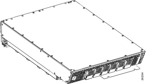
In the fixed configuration power system, different power shelves are used for DC, AC Wye, and AC Delta input power. Each power shelf contains three AC rectifiers or three DC PEMs and an alarm module. This figure shows a front view of a fixed configuration AVC Wye power shelf with AC rectifiers and alarm module installed. The front view of a fixed configuration AC Delta power shelf with AC rectifiers and alarm module installed and a fixed configuration DC power shelf with DC PEMs and alarm module installed are similar.
Note | Although differences exist among the different power shelf types (AC Wye, AC Delta, and DC), they are installed in the same manner. |
|
1 |
Alarm module |
3 |
AC rectifier 1 |
|
2 |
AC rectifier 2 |
4 |
AC rectifier 0 |
This figure shows the AC Wye power shelf with a 5-wire Wye cord and an IEC 60309 plug rated 415V/32A, IP44, 3W+N+PE; it is 4 meters long. The power shelf has five corresponding leads: three active (hot), one neutral, and one ground.
|
1 |
Lead 1 (L1) |
4 |
Lead 4 (L4, neutral) |
|
2 |
Lead 2 (L2) |
5 |
Ground |
|
3 |
Lead 3 (L3) |
|
|
This figure shows the Delta power shelf. The power cord has a 4-pin 460P9W plug (3W+PE) that plugs into a 460R9W power receptacle.
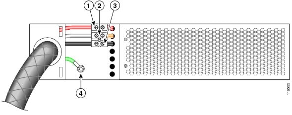
|
1 |
Lead 1 (L1) |
3 |
Lead 3 (L3) |
|
2 |
Lead 2 (L2) |
4 |
Ground |
- Fixed Configuration Power Architecture
- Fixed Configuration Chassis Load Zones
- DC Fixed Configuration Power Systems
- AC Fixed Configuration Power Systems
- Alarm Module for Fixed Configurations
Fixed Configuration Power Architecture
AC and DC fixed configuration power systems use A and B power shelves to provide reliable, 2N redundant power to all chassis components.
Input power enters the chassis through the two power shelves and is distributed to the A or B power bus. Both bus bars distribute power through the midplane to the line cards, switch fabric, RP, and fan controller card slots. For details showing the FCC power routing distribution for a fixed DC configuration, see Figure 3 and for an AC fixed configuration, see Figure 1.
- The A power shelf supplies –54 VDC to the A bus bar.
- The B power shelf supplies –54 VDC to the B bus bar.
Because chassis components are powered by both A and B power inputs, the FCC chassis can continue to operate normally, if:
- One AC PM or DC PM fails
- One entire power shelf fails
- One bus bar fails
It takes two failures for the system to be degraded. In addition, for the degradation to occur, the failures must occur in both the A and B sides of the power architecture to affect the same load zone.
Individual chassis components have power-related devices (OR-ing diodes, inrush control circuits, and EMI filters) that are part of the chassis power architecture. These power-related devices form part of the dual power source (A and B bus) architecture, and enable online insertion and removal (OIR) of the component, which is also called hot-swapping.
Fixed Configuration Chassis Load Zones
The DC power system distributes power in the chassis through four load zones, which provide power redundancy and reliability. Each load zone receives power from both bus bars (A and B). This ensures that each card and module in the chassis is powered by both power shelves.
An FCC can lose a single power module or an entire power shelf and still have the power to operate. For a load zone to lose complete power, a power module in each power shelf would have to fail.
This figure shows the four load zones on the SFC side of the FCC.
|
1 |
Power Module A0 |
6 |
Power Zone 4 |
|
2 |
Power Module A0 |
7 |
Lower SFC Card Cage |
|
3 |
Fan Tray 0 (FT0) |
8 |
Fan Tray 1 (FT1) |
|
4 |
Power Zone 2 |
9 |
Power Zone 3 |
|
5 |
Upper SFC Card Cage |
10 |
Power Zone 1 |
As shown in above figure, each power module (DC PEM) powers two load zones:
- Power module A0 powers zones 1 and 2 (Z1 and Z2)
- Power module A1 powers zones 3 and 4 (Z3 and Z4)
- Power module B0 powers zones 1 and 2 (Z1 and Z2)
- Power module B1 powers zones 3 and 4 (Z3 and Z4)
Above figure also shows which zones power which chassis slots:
- Load zone 1 (Z1) powers chassis slots 0 through 8
- Load zone 2 (Z2) powers chassis slots 9 through 11 and the SCGE0 (2-port or 22-port) card
- Load zone 3 (Z3) powers chassis slots 12 through 20
- Load zone 4 (Z4) powers chassis slots 21 through 23 and the SCGE1 (2-port or 22-port) card
This figure shows the four load zones on the OIM side of the FCC.

|
1 |
Power Zone 1 |
4 |
Lower OIM Card Cage |
|
2 |
Upper OIM Card Cage |
5 |
Power Zone 4 |
|
3 |
Power Zone 3 |
6 |
Power Zone 2 |
The above figure also shows which zones power which chassis slots on the OIM side of the chassis:
- Load zone 2 (Z2) powers the OIM-LED0 card and chassis slots 11 through 9
- Load zone 1 (Z1) powers chassis slots 8 through 0
- Load zone 4 (Z4) powers the OIM-LED1 card and chassis slots 23 through 21
- Load zone 3 (Z3) powers chassis slots 20 through 12
- The fan trays (FT0 and FT1) receive their operating power from the SCGE (2-port or 22-port) cards (SCGE0 and SCGE1).
DC Fixed Configuration Power Systems
The FCC DC power system receives 9300 W maximum when powering a full chassis. The DC PEMs can deliver 8800 W of power to the system. The remaining 500 W equal the efficiency of the PEM. The DC power system, which provides 2N power redundancy for the routing system, contains these components:
- Two DC power shelves—Contain the input DC power connectors and house the DC power entry modules (PEMs).
- Two DC PEMs (for each power shelf)—Take input DC power from the power shelf, provide filtering and surge protection, and pass the power to either the A or B bus bar. Each PEM is field-replaceable.
Each power shelf and each PEM has its own circuit breaker.
- Fixed Configuration DC Power Shelf
- Fixed Configuration DC Power Entry Module
- Fixed Configuration PEM Indicators
Fixed Configuration DC Power Shelf
The DC power shelf is the enclosure that houses two DC power entry modules (PEMs), the alarm module, and power distribution connections and wiring. The DC power shelf is installed in the FCC from the front and plugs into the chassis power interface connector panel.

The DC power shelf physical dimensions are:
- Height—6.2 in. (15.8 cm)
- Width—20 in. (50.8 cm)
- Depth—25 in. (63.5 cm)
- Weight—38 lb (17.24 kg) (without DC PEMs)
Each power shelf has four input power connectors to connect input DC power (nominal –48 VDC or –60 VDC, 60 A). Each connector consists of two terminals (– and +). Each terminal consists of two M6 threaded studs, 0.6 inches long, and centered 0.625 inches apart. The terminals have a safety cover.
A service processor is located in the alarm module that monitors the condition of each PEM and provides status signals that indicate the health of the power supplies.
This figure is a block diagram of the connections between the DC power shelves and FCC. See the Cisco CRS Carrier Routing System Fabric Card Chassis Installation Guide for information about the input power connections to the DC power shelf.
Each DC power shelf supports two PEMs. Each power shelf accepts four pairs of 60 A battery feeds. Input DC power enters the power shelf and is processed by the PEMs before being distributed to the chassis backplane. The PEMs perform inrush current limiting, EMI filtering, surge protection, and circuit isolation on the input DC power, and then distribute the power to either the A or B bus bar in the chassis backplane.
To provide 2N redundancy, one DC power shelf powers the A bus and the other shelf powers the B bus. Load zones in the chassis backplane provide power from both the A and B buses to each card and module in the chassis. For detailed information about how power is distributed through the chassis, see the Fixed Configuration Power Architecture and the Fixed Configuration Chassis Load Zones.
A service processor is located in the alarm module that monitors the condition of each PEM and provides status signals to indicate the health of the power supplies.
This figure shows the wiring of a DC power shelf. Four sets of two-wire 60 A DC power are wired into the DC power shelf at a terminal block. The DC power is then routed through the shelf circuit breaker to the two DC PEMs (A0 and A1) in the power shelf. The DC PEMs are passive units that provide power conditioning to the system. PEMs provide circuit protection, EMI filtering, soft-start circuitry, and OIR for the system. Each DC PEM powers two of the chassis load zones.
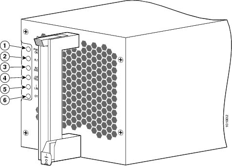
Fixed Configuration DC Power Entry Module
The DC power entry module (PEM), shown in the below figure, processes input power from the power shelf and passes the power to the A or B bus bar. A PEM is field-replaceable.

|
1 |
PWR OK |
4 |
BREAKER TRIP |
|
2 |
FAULT |
5 |
OT |
|
3 |
DC INPUT FAIL |
|
|
The DC PEM physical dimensions are:
- Height—5.4 in. (13.7 cm)
- Width—5.3 in. (13.5 cm)
- Depth—18 in. (45.7 cm)
- Weight—18 lb (8.2 kg)
Two –48/–60 VDC inputs enter the PEM at the rear of the power shelf through a connector on the power shelf backplane. The PEM performs inrush current limiting, EMI filtering, surge protection, and circuit isolation to process the power before it exits the PEM and is distributed to the chassis backplane.
A service processor is located in the alarm module that monitors each PEM and reports the status to the system controller function on the route processor. The service processor detects whether the PEM is present and monitors PEM output voltages and current and fault and alarm conditions (see the Fixed Configuration PEM Indicators).
Each PEM contains an ID EEPROM that stores information used by control software, including part number, serial number, assembly deviation, special configurations, test history, and field traceability data.
Fixed Configuration PEM Indicators
Each DC PEM has power and status indicators. DC PEM indicators are powered by both DC power shelves; therefore, the indicators are operational even when the PEM is not being powered from its input voltage. The Fixed Configuration DC PEM Status Indicators table lists the PEM status indicators and their functions. The Fixed Configuration DC PEM LED Conditions table lists the conditions of the LEDs under certain failure conditions.
|
Name |
Color |
Function |
|---|---|---|
|
PWR OK |
Green |
The PEM is operating normally with power. |
|
FAULT |
Yellow |
A PEM fault was detected (for example, failed bias supply, over temperature or over current, or DC output out of range). |
|
DC INPUT FAIL |
Yellow |
No DC input to the PEM is present, or DC input is out of range. |
|
OT |
Yellow |
The PEM is overheated and has been shut down. |
|
BREAKER TRIP |
Yellow |
The circuit breaker has tripped and is in the off position. |
|
Condition |
PWR OK LED |
FAULT LED |
DC INPUT FAIL LED |
OT LED |
BREAKER TRIP LED |
|---|---|---|---|---|---|
|
No fault (power is on) |
On |
Off |
Off |
Off |
Off |
|
Failed DC power |
Off |
Off |
On |
Off |
Off |
|
Overheated temperature |
Off |
On |
Off |
On |
Off |
|
Tripped breaker |
Off |
Off |
Off |
Off |
On |
AC Fixed Configuration Power Systems
The fixed configuration AC power system provides 8800 W to power the FCC. The AC power system, which provides 2N power redundancy for the routing system, contains these components:
- Two AC power shelves (per chassis)—Contain the input AC power connectors and hold the AC rectifier modules. The power shelves are available in either AC Delta or AC Wye configurations. The chassis requires two power shelves of the same type (Delta or Wye).
- Three AC rectifier modules (per power shelf)—Convert 200 to 240 VAC input power to 54 VDC used by the FCC. Each AC rectifier is field-replaceable.
- Each power shelf has its own circuit breaker and each AC rectifier has its own circuit breaker.
Two versions of the 3-phase AC power shelf are available to support AC Delta or AC Wye input configurations. Each version of the AC power shelf has a different part number. The input AC power for each type of power shelf is:
- The AC Wye power shelf has a Wye 3-phase, 5-wire connection: 200 to 240(L-N)/346 to 415(L-L) VAC, 3W+N+PE, 50-60 Hz, 25 A. For redundant operation, two 3-phase Wye branch circuits are required: 40 A (North America) or 32 A (International). One power connection to each power shelf.
Two versions of the 3-phase AC power shelf are available to support AC Delta or AC Wye input configurations. Each version of the AC power shelf has a different part number. The input AC power for each type of power shelf is:
- The AC Wye power shelf has a Wye 3-phase, 5-wire connection: 200 to 240 (L-N) /346 to 415 (L-L) VAC, 3W+N+PE, 50-60 Hz, 24 A. For redundant operation, two 3-phase Wye branch circuits are required: 40 A (North America) or 32 A (International). One power connection is allocated to each power shelf.
- The AC Delta power shelf has a Delta 3-phase, 4-wire connection: 200 to 240 VAC, 3-phase, 3W+PE, 42 A, 50 to 60 Hz. For redundant operation, two 3-phase Delta 60-A branch circuits are required. One power connection is allocated to each power shelf.
Note | The power cables for the power shelves are not shipped preattached. |
- Fixed Configuration AC Delta Power Shelf
- Fixed Configuration AC Wye Power Shelf
- Fixed Configuration AC Rectifier
- Fixed Configuration AC Rectifier Indicators
Fixed Configuration AC Delta Power Shelf
The AC Delta power shelf is the enclosure that houses three AC rectifier modules, an alarm module, and power distribution connections and wiring. The AC Delta power shelf, shown in AC Delta Power Shelf, is installed in the FCC from the front and plugs into the chassis power interface connector panel. See Fixed Delta Power Shelf - Rear View for the back panel wiring.
|
1 |
Alarm module |
3 |
AC rectifier 1 |
|
2 |
AC rectifier 2 |
4 |
AC rectifier 0 |
The AC Delta power shelf physical dimensions are:
- Height—6.2 in. (15.8 cm)
- Width—20 in. (50.8 cm)
- Depth—25 in. (63.5 cm)
- Weight—36 lb (16.3 kg) (without AC rectifier modules)
This figure illustrates the basic power architecture of an AC Delta-powered FCC.
Input AC power enters the power shelf and is distributed to the three AC rectifiers in the shelf. The AC rectifiers convert AC power into DC power, provide filtering, and then pass the DC power to either the A or B bus bar in the chassis backplane.
To provide 2N redundancy, one AC power shelf powers the A bus and the other shelf powers the B bus. Load zones in the chassis backplane provide power from both the A and B buses to each card and module in the chassis. For detailed information about how power is distributed through the chassis, see the Fixed Configuration Power Architecture and the Fixed Configuration Chassis Load Zones.
A service processor is located in the alarm module that monitors the condition of each AC rectifier and provides status signals that indicate the health of the power supplies.
Note | The same AC rectifier is used in both the AC Delta and AC Wye power shelves. |
This figure shows the wiring of an AC Delta power shelf. Four-wire AC Delta 3-phase power is wired into the AC Delta power shelf at a terminal block (TB1). The 3-phase power is then routed through the shelf circuit breaker to the three AC rectifiers (PS0, PS1, and PS2) in the power shelf. The AC rectifiers convert the AC power into 54.5 VDC power for the chassis. Each AC rectifier powers two of the chassis load zones.

Fixed Configuration AC Wye Power Shelf
The AC Wye power shelf (CRS-FCC-PS-ACW) is the enclosure that houses three AC rectifier modules, an alarm module, and power distribution connections and wiring. The power shelf is installed in the FCC from the front and plugs into the chassis power interface connector panel.
|
1 |
Alarm module |
3 |
AC rectifier 1 |
|
2 |
AC rectifier 2 |
4 |
AC rectifier 0 |
The AC Wye power shelf physical dimensions are:
- Height—6.2 in. (15.8 cm)
- Width—20 in. (50.8 cm)
- Depth—25 in. (63.5 cm)
- Weight—36 lb (16.3 kg) (without AC rectifier modules)
Input AC power enters the power shelf and is distributed to the three AC rectifiers in the power shelf. The AC rectifiers convert AC power into DC power, provide filtering, and then pass the DC power to either A or B bus bar in the chassis midplane. For redundancy, one AC power shelf powers the A bus and the other shelf powers the B bus. Load zones in the chassis midplane provide power from both the A and B bus to each card and module in the chassis.
The power shelf also has a service processor module that monitors the condition of each AC rectifier and provides status signals that indicate the health of the power supplies.
Note | The same AC rectifier is used in AC Delta and AC Wye power shelves. |
This figure shows the wiring of an AC Wye power shelf. 5-wire AC Delta 3-phase power is wired into the AC Wye power shelf at a terminal block (TB1). The 3-phase power is then routed through the shelf circuit breaker to the three AC rectifiers in the power shelf. The AC rectifiers (PS0, PS1, and PS2) convert the AC power into the DC (54.5 VDC) power. Each AC rectifier powers two of the chassis load zones. The DC power is distributed to the FRUs in the various load zones through the bus bar and the chassis backplane.

Fixed Configuration AC Rectifier
The AC rectifier is an AC power supply that converts input AC power into the DC power necessary to power chassis components. The same rectifier is used for both AC Wye and AC Delta power shelves.
The rectifier takes input AC power from the power shelf, rectifies the AC into DC, provides filtering and control circuitry, provides status signaling, and passes the DC power to either the A or the B bus bar in the chassis backplane. Each AC rectifier has a self-contained cooling fan that draws air through the module.
|
1 |
PWR OK |
4 |
OT |
|
2 |
FAULT |
5 |
BREAKER TRIP |
|
3 |
CD INPUT FAIL |
6 |
ILIM |
The AC rectifier physical dimensions are:
- Height—5.43 in. (13.8 cm)
- Width—5.24 in. (13.3 cm)
- Depth—18 in. (45.7 cm)
- Weight—19 lb (8.6 kg)
As shown in above figure, a single phase of the 3-phase AC input power (200 to 240 VAC or 346 to 415 VAC) is routed to each AC power rectifier in the AC power shelf. The AC power enters the AC rectifier at the rear of the power shelf through a connector located on the power shelf midplane. After the power enters the AC rectifier, internal circuits rectify the AC into DC, filter and regulate it. The conversion from AC to DC is done in two stages:
- The first stage is for power factor correction (PFC). The PFC process converts the AC to 350 VDC power. The PFC maintains the AC input current to be sinusoidal and in-phase with the AC input. The result is near unity power factor.
- The second stage is DC to DC conversion. The DC to DC process converts the 350 VDC primary side power to 54 VDC isolated secondary power.
A microprocessor in the AC rectifier monitors the status of each AC rectifier. The microprocessor communicates with the system controller on the route processor (RP). The microprocessor circuitry monitors these AC rectifier fault and alarm conditions:
- Fault—Indicates a failure in an AC rectifier, such as failed bias supply, over temperature or current limit. It includes a warning that the DC output is out side the allowable output range.
- AC Input Fail—Indicates that the AC input voltage is out of range.
- Circuit Breaker Trip—Indicates that the AC rectifier circuit breaker has tripped.
- Over temperature—Indicates that the AC rectifier has exceeded the maximum allowable operating temperature.
- AC Rectifier Present—Indicates that the rectifier is present and seated properly in the power shelf.
- Voltage and Current Monitor signals (Vmon, Imon)—Indicates that the output voltages and currents provided by the AC rectifier are within range.
Each AC rectifier contains an ID EEPROM that stores information used by control software, including part number, serial number, assembly deviation, special configurations, test history, and field traceability data.
Fixed Configuration AC Rectifier Indicators
Each AC rectifier has power and status indicators. The AC rectifier indicators receive power from both AC power shelves; therefore, the indicators are operational even when the AC rectifier is not powered from its input voltage.
AC Rectifier Status Indicators lists the AC rectifier status indicators and their functions. AC Rectifier LED Conditions lists the LED readings during failure conditions.
|
Name |
Color |
Function |
|---|---|---|
|
PWR OK |
Green |
AC rectifier is operating normally with power. |
|
FAULT |
Yellow |
A fault has been detected in the AC rectifier. |
|
AC INPUT FAIL |
Yellow |
AC input is out of range, or is not being provided to the AC rectifier. |
|
OT |
Yellow |
AC rectifier is overheated and it has been shut down. |
|
BREAKER TRIP |
Yellow |
Input circuit breaker is off (in the off position). |
|
ILIM |
Yellow |
AC rectifier is operating in a current limiting condition. |
|
Condition |
PWR OK LED |
FAULT LED |
AC INPUT FAIL LED |
OT LED |
BREAKER TRIP LED |
ILIM LED |
|---|---|---|---|---|---|---|
|
No fault (power is on) |
On |
Off |
Off |
Off |
Off |
Off |
|
Failed AC power |
Off |
Off |
On |
Off |
Off |
Off |
|
Overheated temperature |
Off |
On |
Off |
On |
Off |
Off |
|
Tripped breaker |
Off |
Off |
Off |
Off |
On |
Off |
|
Current limit |
Off |
Off |
Off |
Off |
Off |
On |
Alarm Module for Fixed Configurations
This section describes an alarm module in a fixed configuration power supply in the FCC. An alarm module can be installed only in the far right slot of the power shelf.
Each AC or DC power shelf contains an alarm module, which monitors the status of the power shelf and provides an external interface for system alarms. A dedicated alarm module slot exists on the right side of every power shelf. The same alarm module is used in all power shelves.
Note | Only safety extra-low voltage (SELV) circuits can be connected to the ALARM connector on the alarm module faceplate. The maximum rating for the alarm circuit is 2 A, 50 VAC. |
|
1 |
External alarm connector |
3 |
LED display |
|
2 |
Alarm LEDs |
|
|
The physical dimensions of the alarm module are:
- Height—5.5 in (14 cm)
- Depth—18 in. (45.72 cm)
- Width—3.2 in. (8.13 cm)
- Weight—4.2 lb (2 kg)
The alarm module performs these functions:
-
Alarm output, both LEDs and relay:
- LEDs—Three large LEDs (critical, major, and minor) indicate the status of the chassis. The LEDs are controlled by software on the RP system controller. For redundancy, each alarm indicator has two LEDs (to ensure that alarm status is visible even if one of the LEDs fails).
- Relay—The alarm module output function consists of a relay and its associated driver. As directed by the system controller, the service processor module on the alarm module activates the relay. The alarm relay connector is a standard DA-15S connector.
- PEM or AC rectifier status monitoring—The alarm module monitors the performance and status of the AC rectifiers or DC PEMs. The module monitors performance and error conditions that may exist on the AC rectifier or PEM. Because it receives power from both power shelves, the alarm module can report the status of an unpowered shelf.
-
Alarm monitoring—An LED display provides information about the status of the chassis.
- If the system is operating properly, “IOS-XR” appears in the LED display.
- If an alarm occurs, this LED indicates the card or component that is having a problem. For example, if a fan tray is missing, the display indicates which fan tray is missing. A display such as “0 1 SP” indicates that the MSC in rack 0, slot 1 is having a problem.
This table lists the pinouts for the alarm relay connector.
|
Signal Name |
Pin |
Description |
|---|---|---|
|
Alarm_Relay_NO |
1 |
Alarm relay normally open contact |
|
Alarm_Relay_COM |
2 |
Alarm relay common contact |
|
Alarm_Relay_NC |
9 |
Alarm relay normally closed contact |
Only pins 1, 2, and 9 are available for customer use. The remaining pins are for Cisco manufacturing test and should not be connected. Use a shielded cable for connection to this port for EMC protection.
Modular Configuration Power Supply
This section contains these topics for modular configuration power systems.
- Modular Configuration Power Architecture
- Modular Configuration Chassis Power Zones
- DC Modular Configuration Power Systems
- AC Modular Configuration Power Systems
- Alarm Module for Modular Configurations
Modular Configuration Power Architecture
The modular configuration power system includes these major components:
-
Two (redundant) AC or DC power shelves (different power shelves are used for AC and DC power)
- Up to six 3000 W AC power modules (PMs) per shelf; however, the product is shipped with three
- Up to six 2100 W DC PMs per shelf; however, the product is shipped with four
- Removable alarm module, one per power shelf
If you have 3-phase AC Delta or AC Wye at your equipment, a Cisco CRS power distribution unit (PDU) will be required to convert 3-phase AC input power to single-phase AC input power for the power shelf. At the shelf level, the power system provides 2N redundancy; the PMs themselves provide load-share redundancy.
Note | For further information on the AC power system PDU, refer to the Cisco CRS 3-Phase AC Power Distribution Unit Installation Guide. |
The power architecture and power distribution of a Cisco CRS FCC, as shown in the below figure, is the same for fixed and modular configuration power systems.

Above figure shows AC or DC input power enters the chassis through the two power shelves and is distributed to the A or B power bus. Both bus bars distribute power through the backplane to the SCGE cards (2-port or 22-port), fan trays, and SFCs.
- The A power shelf supplies –48 VDC to the A bus bar.
- The B power shelf supplies –48 VDC to the B bus bar.
Because chassis components are powered by both A and B power inputs, the FCC can continue to operate normally, if:
- One AC power module or DC power module fails
- One entire power shelf fails
- One bus bar fails
Two failures have to occur for the system to be degraded. In addition, for the degradation to occur, the failures must occur in both the A and B sides of the power architecture and affect the same load zone.
Individual chassis components have power-related devices (online insertion and removal [OIR] diodes, inrush control circuits, and EMI filters) that are part of the chassis power architecture. These power-related devices form part of the dual power source (A and B buses) architecture and enable OIR of the component, which is also called hot-swapping.
Modular Configuration Chassis Power Zones
The DC power system distributes power in the chassis through four load zones, which provide power redundancy and reliability. Each load zone receives power from both bus bars (A and B). This ensures that each card and module in the chassis is powered by both power shelves.
An FCC can lose a single power module or an entire power shelf and still have the power to operate. For a load zone to lose complete power, a power module in each power shelf would have to fail.
This figure shows the four load zones on the SFC side of the FCC.
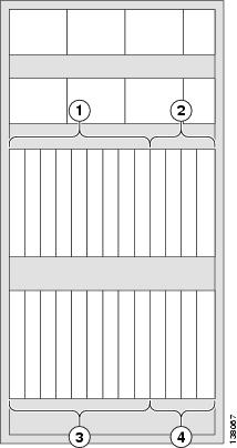
|
1 |
Power zone 1 |
3 |
Power zone 3 |
|
2 |
Power zone 2 |
4 |
Power zone 4 |
These properties apply to the power shelves and power zones:
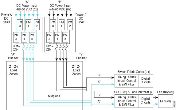
- Power shelf A supports everything in it. PM 0-5 supports everything in the entire chassis that needs power which are cards, fans, alarm modules. CB1 supports Z1, CB2 supports Z2 ... CB4 supports Z4
- Power shelf B supports everything in it. PM 0-5 supports everything in the entire chassis that needs power which are cards, fans, alarm modules. CB1 supports Z1, CB2 supports Z2 ... CB4 supports Z4
- Power zone 1 supports chassis slots 0 to 8
- Power zone 2 supports chassis slots 9 to 11
- Power zone 3 supports chassis slots 12 to 20
- Power zone 2 supports chassis slots 21 to 23
- The fan trays (FT0 and FT1) receive their operating power from the SCGE cards (SCGE0 and SCGE1)
DC Modular Configuration Power Systems
The FCC DC modular power system provides up to 12,600 W DC power to the chassis. The DC modular power system contains these components:
- Two DC power shelves. Each power shelf contains the DC input power connections and houses the DC power modules and alarm module.
- Up to six DC power modules per shelf. Each power module has its own fuse and is field-replaceable.
- Modular Configuration DC Power Shelf
- Modular Configuration DC Power Module
- Modular Configuration DC Power Module Indicators
Modular Configuration DC Power Shelf
The DC modular power shelf is the enclosure that houses the DC PMs, the alarm module, and power distribution connections and wiring. The power shelf installs in the FCC from the front and plugs into the chassis power interface connector panel.
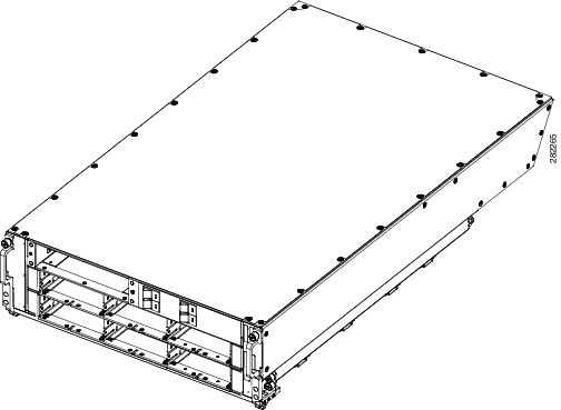
This figure shows the front view of the modular configuration DC power shelves.

This figure shows the rear view of the modular configuration DC power shelves.
The DC power shelf physical dimensions are:
- Height—6.2 in. (15.8 cm)
- Width—20 in. (50.8 cm)
- Depth—25 in. (63.5 cm)
- Weight—38 lb (17.2 kg) (without DC power modules)
Each power module has its own power connector to connect input DC power (nominal –48/–60 VDC, 50 A or 40 A service). Each connector consists of two terminals (– and +). Each terminal consists of two M6 threaded studs, 0.6 inches long, and centered 0.625 inches apart. The terminals have a safety cover.
Each DC power shelf supports up to six power modules, and accepts two 60 A battery feeds per power module. Input DC power enters the power shelf and is processed by the power modules before being distributed to the chassis midplane. The power modules perform inrush current limiting, EMI filtering, surge protection, and circuit isolation on the input DC power, and then distribute the power via the internal bus bar in the chassis midplane.
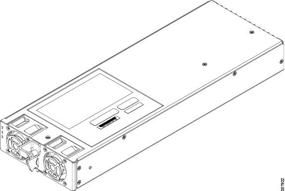
Modular Configuration DC Power Module
Each DC power module provides 2100 W. The DC power module shown in the below figure passes the power via the internal bus bar to the system. power modules are field-replaceable.
The DC power module physical dimensions are:
-
Height—1.6 in. (4.06 cm)
-
Width—4.0 in. (10.16 cm)
-
Depth—13.56 in. (34.44 cm)
Two –48 or –60 VDC inputs enter the power module at the rear of the power shelf, and exits the power module and is distributed to the chassis midplane. The power module does not perform any filtering or status monitoring. Instead, the alarm module provides these features, monitoring power module status and processing alarm functions.
Each power module contains an ID EEPROM that stores information used by control software, including part number, serial number, assembly deviation, special configurations, test history, and field traceability data.
Modular Configuration DC Power Module Indicators
These three LED status indicators are located on the front of each modular configuration DC power module:
-
Input OK - Green
-
Output OK - Green
-
Internal Fault - Red
The power module LED status indicators are not visible when the front grille is installed.
This table lists the modular configuration power module status indicators and their functions.
|
Name |
Color |
Function |
|---|---|---|
|
Input OK |
Green |
Input OK LED turns on continuously when input voltage is present and within the regulation range. Input OK LED flashes when input voltage is present, but not within the regulation range. Input OK LED is off when input voltage is not present. Input OK LED flashes when hot-unplugging the power supply from the power shelf to indicate that there will be energy in the power supply until the input bulk capacitor is completely discharged, or the housekeeping circuit is shut down. |
|
Output OK |
Green |
Output OK LED turns on continuously when power supply output voltage is on. Output OK LED flashes when power supply output voltage is in a power limit or an overcurrent situation. |
|
Internal Fault |
Red |
Internal Fault LED turns on continuously when there is an internal fault in the power module. |
The Internal Fault LED on the DC power module is turned on continuously to indicate that one or more of these internal faults is detected inside the power supply:
-
5V out of range
-
Output Stage OT
-
Fan Fault
-
OR-ing fault (Output voltage less than bus voltage)
-
OC shutdown
-
OT shutdown
-
OV shutdown
-
Input stage OT
-
Fault induced shutdown occurred
-
Thermal sensor fault
-
Vout out of range
-
Boost Vbulk fault
When all faults have been removed and the power supply is operating normally, the Internal Fault LED is turned off.
AC Modular Configuration Power Systems
The modular configuration AC power system provides up to 15,000 W to power the FCC. The AC power system, which provides 2N power redundancy for the routing system, contains these components:
Two AC power shelves (per chassis). Each power shelf contains the input AC power connectors and holds the AC power modules. The chassis requires two power shelves for redundancy.
-
Up to six AC power modules per power shelf.
-
Each AC power module has its own fuse and is field-replaceable.
- Modular Configuration AC Power Shelf
- Modular Configuration AC Power Module
- Modular Configuration AC Power Module Indicators
Modular Configuration AC Power Shelf
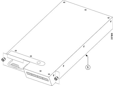
The AC power shelf is the enclosure that houses the AC power modules, the alarm module, and power distribution connections and wiring. The AC power shelf, shown in the below figure, is installed in the FCC from the front and plugs into the chassis power interface connector panel.
The AC power shelf physical dimensions are:
-
Height—6.2 in (15.8 cm)
-
Width—20 in (50.8 cm)
-
Depth—25 in (63.5 cm)
-
Weight—36 lb (16.3 kg) (without AC power modules)
Note | The power cables for the power shelves do not come pre-attached. |
See the Cisco CRS Carrier Routing System Fabric Card Chassis Installation Guide for detailed information about the input power connections to the AC power shelf.
Each AC power shelf supports up to four AC power modules. The AC power modules convert AC power into DC power, provide filtering, and then distribute the DC power to the chassis midplane. For detailed information about how power is distributed through the chassis, see the Modular Configuration Power Architecture section.
The power shelf also has a service processor module that monitors the condition of each AC power module and provides status signals that indicate the health of the power supplies (see the Modular Configuration AC Power Module Indicators section).
Modular Configuration AC Power Module
The AC power module is an AC power supply that converts single phase input AC power into the DC power necessary to power chassis components.
The AC power module takes input AC power from the power shelf, converts the AC into DC, provides filtering and control circuitry, provides status signaling, and passes the DC power to the chassis midplane.
Each power module has its own power connector to connect input AC power. The input AC power for each power module is:
-
Each AC power module has a single-phase, 3-wire connection:
Input: 200 to 240 VAC, 50 to 60 Hz, 16 A.
Tolerance: +/-10%(180 to 264) VAC, 50 to 60 Hz, 16 A.
-
A 3-pin IEC-320 C21 90 degree female plug is inserted into a 3-pin IEC-320 C22 male plug at the rear of each power module.
This figure shows the AC modular configuration power module
The AC power module physical dimensions are:
-
Height—1.6 in (4.06 cm)
-
Width—4.75 in (12.0.6 cm)
-
Depth—13.56 in (34.44 cm)
The AC power enters the AC power at the rear of the power shelf. When the power enters the AC power module, internal circuits rectify the AC into DC, filter and regulate it. Each AC power module provides two output voltages:
-
Output Voltage 1 is -54 VDC at 55.5A
-
Output Voltage 2 is +5Vaux at 0.75A
Each AC power module contains an ID EEPROM that stores information used by control software, including part number, serial number, assembly deviation, special configurations, test history, and field traceability data.
Modular Configuration AC Power Module Indicators
These three LED status indicators are located on the front of each DC power module:
-
Input OK - Green
-
Output OK - Green
-
Internal Fault - Red
This table lists the power module status indicators and their functions.
|
Name |
Color |
Function |
|---|---|---|
|
Input OK |
Green |
Input OK LED turns on continuously when input voltage is present and within the regulation range. Input OK LED flashes when input voltage is present, but not within the regulation range. Input OK LED is off when input voltage is not present. Input OK LED flashes when hot-unplugging the power supply from the power shelf to indicate that there will be energy in the power supply until the input bulk capacitor is completely discharged, or the housekeeping circuit is shut down. |
|
Output OK |
Green |
Output OK LED turns on continuously when power supply output voltage is on. Output OK LED flashes when power supply output voltage is in a power limit or an overcurrent situation. |
|
Internal Fault |
Red |
Internal Fault LED turns on continuously when there is an internal fault in the power module. |
The Internal Fault LED on the DC power module is turned on continuously to indicate that one or more of these internal faults is detected inside the power supply:
-
5V out of range
-
Output Stage OT
-
Fan Fault
-
OR-ing fault (Output voltage less than bus voltage)
-
OC shutdown
-
OT shutdown
-
OV shutdown
-
Input stage OT
-
Fault induced shutdown occurred
-
Thermal sensor fault
-
Vout out of range
-
Boost Vbulk fault
When all faults have been removed and the power supply is operating normally, the Internal Fault LED is turned off.
Alarm Module for Modular Configurations
Each modular configuration DC power shelf contains an alarm module. It monitors the presence and performance of the modular configuration AC and DC power modules. It also monitors the status of the power shelf and provides an external interface for system alarms. This figure shows a modular configuration alarm module.
-
Side of alarm module to be installed on the right side of the opening
The alarm module receives power from both power shelves. As a result, it can report the status of an unpowered shelf as well as that of a powered shelf.
The alarm module performs these functions:
-
Alarm outputs, both relay and LEDs:
-
Alarm LEDs—Three large LEDs (Critical, Major, and Minor) indicate the status of the chassis. The LEDs are controlled by software on the RP system controller. For redundancy, each alarm indicator has two LEDs (to ensure that alarm status is visible even if one of the LEDs fails).
-
Relay—The alarm module output function consists of a relay and its associated driver. As directed by the system controller (on the RP or the switch controller/fan controller (SCFC), depending on the chassis type), the service processor module on the alarm module activates the relay. The alarm relay connector is a standard DA-15S connector.
-
-
AC or DC power module status monitoring — The alarm module monitors the performance and status of the AC or DC power modules. The alarm module monitors Power Good, Power Fail, Internal Fault, Over Temp conditions, AC or DC power module presence, and voltage and current output levels. The alarm module can report these statuses even for an unpowered shelf.
-
Alarm monitoring—An LED display provides information about the status of the chassis.
-
If the system is operating properly, “IOS-XR” appears in the LED display.
-
If an alarm occurs, this LED indicates the card or component that is experiencing a problem. For example, if a fan tray is missing, the display indicates which fan tray is missing. A display such as “0 1 SP” indicates that the MSC in rack 0, slot 1 is experiencing a problem.
-
In the power shelf, a service processor module monitors the status of each power module and communicates with the system controller of the Route Processor (RP). The service processor monitors these power module faults and alarm conditions:
-
Fault—Indicates a failure in a power module, such as failed bias supply, over temperature or current limit. It includes a warning that the DC output is outside the allowable output range.
-
Input Fail—Indicates that the input voltage is out of range.
-
Circuit Breaker Trip—Indicates that the power module circuit breaker has tripped.
-
Over temperature—Indicates that the power module has exceeded the maximum allowable operating temperature.
-
Power Module Present—Indicates that the power module is present and seated properly in the power shelf.
-
Voltage and Current Monitor signals (Vmon, Imon)—Indicate that the output voltages and currents provided by the power module are within range.
This table lists the pin outs for the alarm relay connector.
|
Signal Name |
Pin |
Description |
|---|---|---|
|
Alarm_Relay_NO |
1 |
Alarm relay normally open contact |
|
Alarm_Relay_COM |
2 |
Alarm relay common contact |
|
Alarm_Relay_NC |
9 |
Alarm relay normally closed contact |
Only Pins 1, 2, and 9 are available for customer use. The remaining pins are for Cisco manufacturing test, and should not be connected. Use a shielded cable for connection to this port for EMC protection.
Cisco CRS 3-Phase Power Distribution Unit
This section describes the Cisco CRS Power Distribution Unit (PDU) for the FCC. The PDU is intended for use with the CRS modular power system in environments where 3-phase input power needs to be converted to single phase output power.
The PDU includes an AC Delta or AC Wye power interface to convert 3-phase input power to single phase output. The PDU has power input and power output cords entering and exiting the box. The PDU can be installed in 19 inch racks or other locations such as the sides of the FCC by using custom mounting brackets.
One PDU is required for each modular power shelf installed in the chassis for system redundancy. A PDU can be installed on either the left or right side of the chassis.
There are two versions of the FCC PDU:
Power Distribution Unit D—CRS 3 phase AC Delta input
-
Power Distribution Unit W—CRS 3 phase AC Wye input
This figure shows the Power Distribution Unit that converts 3-phase AC Delta input power to single phase output power.
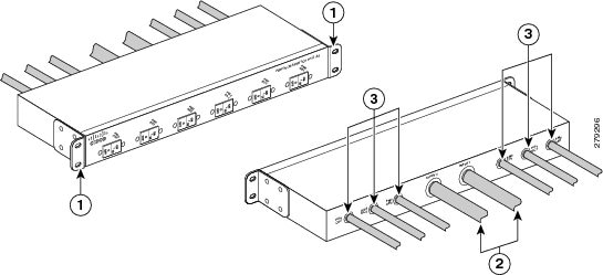
This figure shows the Power Distribution Unit that converts 3-phase AC Wye input power to single phase output power.

The power distribution unit physical dimensions are:
-
Height—2.0 in (5.1 cm)
-
Width—19.3 in (49.1cm)—with rack mounting ears
-
Width—17.5 in (44.4 cm)—without rack mounting ears
-
Depth—6.0 in (15.2 cm)
Note | The power cables for the power distribution unit come pre-attached. |
The FCC PDU is shipped with this hardware for specific configurations:
-
Two single AC Delta PDUs with 19 inch rack mounting bracket. Each AC Delta PDU has two power inputs and six outputs
-
Two Single AC Wye PDUs with 19 inch rack mounting bracket. Each AC Wye PDU has one power input and six outputs
-
FCC PDU mounting bracket kit, available as an optional accessory
Two versions of the AC PDU are available for AC input power, AC Wye and AC Delta. Each PDU has a different Cisco part number, to distinguish it from the other.
-
The AC Wye PDU has a Wye 3-phase, 5-wire input power connection consisting of 3 wire + neutral + protective earthing, or ground wire (3W+N+PE).
Input: 200 to 240 (L-N)/346 to 415 (L-L) VAC, 50 to 60 Hz, 32 A.
Tolerance: +/-10% (180 to 264)(L-N)/(311 to 456)(L-L) VAC, 50 to 60 Hz, 32 A.
-
The AC Wye PDU has six single phase output power connections.
Output: 200 to 240 VAC, 50 to 60 Hz, 16 A.
Tolerance: +/-10%(180 to 264) VAC, 50 to 60 Hz, 16 A.
-
The AC Delta PDU has two Delta 3-phase, 4-wire input power connections, each consisting of 3 wire + protective earthing, or ground wire (3W+PE).
Input: 200 to 240 VAC, 50 to 60 Hz, 27.7 A.
Tolerance: +/-10% (180 to 264) VAC, 50 to 60 Hz, 27.7 A.
-
The AC Delta PDU has six single phase output power connections.
Output: 200 to 240 VAC, 50 to 60 Hz, 16 A.
Tolerance: +/-10%(180 to 264) VAC, 50 to 60 Hz, 16 A.
The power cables are shipped preattached to the power shelves.
-
The Wye input power cord is rated for 415 VAC, 32 A. The power cord has a 5-pin IEC 60309 plug (3W+N+PE).
-
The Wye output cord has a 3-pin IEC-320 C21 90 degree female plug.
-
The Delta input power cord is rated for 250 VAC, 60 A. The power cord has a 4-pin IEC 60309 plug (3W+PE).
The Delta output cord has a 3-pin IEC-320 C21 90 degree female plug.
 Feedback