Cisco CRS Carrier Routing System Multishelf System Description
Bias-Free Language
The documentation set for this product strives to use bias-free language. For the purposes of this documentation set, bias-free is defined as language that does not imply discrimination based on age, disability, gender, racial identity, ethnic identity, sexual orientation, socioeconomic status, and intersectionality. Exceptions may be present in the documentation due to language that is hardcoded in the user interfaces of the product software, language used based on RFP documentation, or language that is used by a referenced third-party product. Learn more about how Cisco is using Inclusive Language.
- Updated:
- December 1, 2016
Chapter: Cisco CRS Multishelf System Hardware Overview
Cisco CRS Multishelf System Hardware Overview
This section provides high-level details of the hardware components that make up the multishelf system. These topics are included in this section:
- Cisco CRS Multishelf System Hardware Overview
- Cisco CRS Series Carrier Routing System Architecture
- Main Features of the Cisco CRS Series Multishelf System
- FCC Overview
Cisco CRS Multishelf System Hardware Overview
This section provides high-level details of the hardware components that make up the multishelf system. These topics are included in this section:
Cisco CRS 16-Slot LCC
As part of the multishelf system, the LCC houses modular services cards (MSCs) or forward processing cards (FPs), switch fabric cards (SFCs), and route processor (RP/PRP) cards. The LCC used in the multishelf system is the same as the one used in the standalone 16-slot CRS except that it uses different fabric cards and has a rear cable management kit. A minimum of one LCC is required to configure a multishelf system.
 Note | Please refer to the Cisco CRS Carrier Routing System 16-Slot Line Card Chassis System Description for details about the LCC. This system description focuses on topics that are specific to the FCC and the overall multishelf system. |
Cisco CRS FCC
The FCC is the centerpiece of the multishelf system. It is used to connect all LCCs together. The FCC houses 24 switch fabric cards (SFCs), 24 optical interface modules (OIMs), 2 OIM light emitting diode (LED) monitoring cards (OIM-LED), and 2 integrated shelf controller Gigabit Ethernet cards. At least one FCC is required to configure a multishelf system
Cisco CRS Series Carrier Routing System Architecture
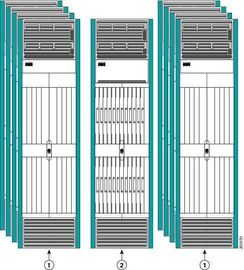
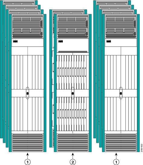
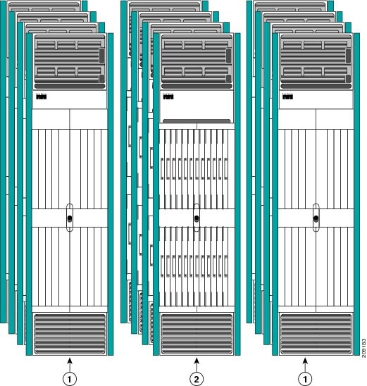
The multishelf system allows multiple LCCs and FCCs to act as a single system. The multishelf system supports up to eight LCCs and one, two, or four FCCs. Single-FCC Multishelf System figure shows a single-FCC multishelf system, Two-FCC Multishelf System figure shows a two-FCC multishelf system, and Four-FCC Multishelf System figure shows a four-FCC multishelf system.
|
1 |
LCC |
2 |
FCC |
|
1 |
LCC |
2 |
FCC |
|
1 |
LCC |
2 |
FCC |
Main Features of the Cisco CRS Series Multishelf System
The main features of the multishelf system include:
- Scalable, nonblocking architecture that allows smooth expansion of the system from one LCC to eight LCCs, providing thousands of high-speed interfaces.
- Support for both 40G CRS-1, 140G CRS-3 and 400G CRS-X in one multishelf system.
- Seamless in-service migration to CRS-3 or CRS-X.
- Distributed control plane that scales the system to millions of interfaces, peers, and routing entries.
- Continuous system operation and availability using a distributed architecture, redundant components, and a self-healing operating system (Cisco IOS XR) that enables a multishelf carrier infrastructure that supports “always-on” operations.
- Carrier class system redundancy on power supplies, fans, controllers, and processing elements.
- Process management through redundancy, failure detection, isolation, tolerance, and recovery.
- Hitless capacity upgrade and In-Service Software Upgrade (ISSU) that supports nonstop forwarding (NSF) and graceful restart extensions of routing and signaling protocols.
- Full online insertion and removal (OIR) support.
- Unique service separation architecture among data, control, and management planes of the Cisco IOS XR software that enables deployment of new features without service disruption. Its component-based model allows components, such as Border Gateway Protocol (BGP) and Intermediate System to Intermediate System (ISIS), to be installed, updated, or deleted individually.
- Logical partitioning in the Cisco CRS system that allows service providers to keep services separate and to consolidate their networks at their own pace.
FCC Overview
The FCC contains the switch fabric and OIMs. The connection between the FCC and LCC is by way of cables from the OIMs in the FCC, to fabric cards in the LCC. The FCC is secured to the floor and has locking front and rear doors. The FCC is a complete rack enclosed in a cabinet, so external racks are not required for the installation of an FCC.
FCC Components
This is a list of the main components of the FCC. It primarily identifies the components that are considered field-replaceable units (FRUs).
The FCC contains:
- Switch fabric cards (SFCs). The SFCs are the main component of the multishelf system. They enable packets to be switched from source to destination. The SFCs on the FCC provide Stage 2 of the three-stage Benes switch fabric for the multishelf system. The S13 SFCs in the LCC provide Stage 1 and Stage 3 of the switch fabric. Three types of SFC are supported: CRS-FCC-SFC for the 40 G CRS-1 system, CRS-FCC-SFC-140 for the 140 G CRS-3 system, and CRS-FCC-SFC-400 for the 400 G CRS-X system. Either eight or twenty-four SFCs are needed, depending on the size of the system. SFCs are located at the front of the FCC. See Multishelf System Switch Fabric for more information.
 Caution | The FCC supports either 40 GB switch fabric cards (CRS-FCC-SFC), 140 GB switch fabric cards (CRS-FCC-SFC-140), or 400 GB switch fabric cards (CRS-FCC-SFC-400). An FCC with a mix of 40 GB,140 GB and 400 GB SFCs is not a supported mode of operation. Such a mode is temporarily allowed only during the upgrade process. |
- Optical Interface Modules (OIMs). The OIMs are passive devices that provide the fiber cross-connect function. The OIMs distribute the fibers within each cable bundle to the SFCs. Each OIM is matted to an SFC. The OIMs are monitored by the OIM-LED card. Each OIM has 9 interfaces. Either 8 or 24 OIMs are needed, depending on the size of the system. The OIMs and cables are located at the rear of the FCC. See Optical Interface Modules and Optical Interface Module LED Card for more information.
- Integrated Shelf Controller Gigabit Ethernet (SCGE) cards. The 22-port SCGE card (CRS-FCC-SC-22GE) serves as a shelf controller for the FCC, providing the control function similar to the RP for LCC. The 22-port integrated GE switch provides the connectivity for control protocol between the FCC and LCC. Two 22-port SCGE cards are included in each FCC for redundancy. Only one shelf controller card is active at a time. The second acts as a “standby” shelf controller, serving as a backup if the active card fails. SCGE cards located at the front of the chassis. See Shelf-Controller Gigabit Ethernet Card for more information.
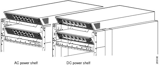
- Fixed configuration power systems and modular configuration power systems are available. Both power configurations use either AC or DC power and are fully redundant. See Fabric Card Chassis Power System for more information.
- Upper and lower fan trays. The fan trays contain fans that push and pull air through the chassis. A removable air filter is also located above the lower fan tray. See Fabric Card Chassis Cooling System for more information.
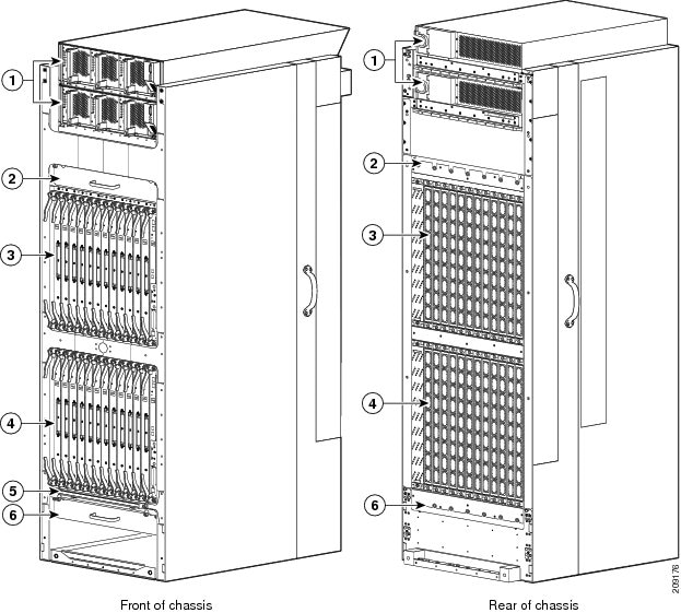
This figure shows the front view (SFC side) and rear view (OIM site) of a fixed configuration AC powered FCC.
|
1 |
Power shelves |
4 |
Lower SFC card cage |
|
2 |
Upper fan tray |
5 |
Chassis air filter |
|
3 |
Upper SFC card cage |
6 |
Lower fan tray |
This figure shows the front (SFC) view of a fixed configuration AC and DC power supply installed at the top of the FCC.
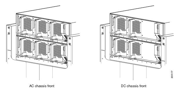
This figure shows the rear (OIM) view of a fixed configuration AC and DC power supply installed at the top of the FCC.

This figure shows the front (SFC) view of a modular configuration AC and DC power supply installed at the top of the FCC.
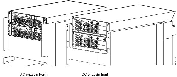
This figure shows the rear (OIM) view of a modular configuration AC and DC power supply installed at the top of the FCC.
FCC Chassis Slot Numbers
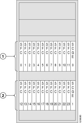
This section identifies the locations and slot numbers for major cards that plug into the FCC. This figure shows the chassis slot numbers on the front (SFC) side of the FCC.
|
1 |
Upper SFC Card Cage |
2 |
Lower SFC Card Cage |
As shown in above figure, the components on the front (SFC) side of the FCC include:
- Upper card cage with 12 switch fabric slots (left to right: 0, 1, 2, 3 . . . 10, 11) followed by one 2-port or 22-port SCGE card slot (SCGE0) on the far right.
- Lower card cage with 12 switch fabric slots (left to right: 12, 13, 14 . . . 21, 22, 23) followed by one 2-port or 22-port SCGE card slot (SCGE1) on the far right.
This figure shows the component numbers on the back (OIM) side of an FCC.

|
1 |
Upper SFC Card Cage |
2 |
Lower SFC Card Cage |
As shown in above figure, the slot numbers on the back (OIM) side of the FCC include:
- Upper OIM cage, 12 OIM slots (0 through 11) and one OIM-LED card (OIM-LED0).
- Lower OIM cage, 12 OIM slots (12 through 23) and one OIM-LED card slot (OIM-LED1).
The OIM slot numbers are aligned with the SFC slot numbers on the other side of the chassis. Because an OIM mates with its associated SFC through the backplane, OIM slot 0 is on the far right side of the chassis looking at it from the OIM (rear) side; SFC slot 0 is on the far left side of the chassis looking at it from the SFC (front) side. OIM slot 0 and SFC slot 0 mate with one another through the backplane, as do all other OIM and SFC slots.
FCC Footprint
This figure is a top view of the FCC footprint (with front and rear cosmetics installed).

|
1 |
Chassis width 23.6 in. (60 cm) |
2 |
Chassis depth 41.3 in. (105 cm) |
FCC Cable Management
The FCC has cable management features for both the front (SFC) side of the chassis and the rear (OIM) side of the chassis. Both the front (SFC) and rear (OIM) sides have vertical cable troughs on the left and right sides of the chassis. In addition, the rear (OIM) side of the chassis has three horizontal cable management brackets close to the card cages.
FCC Exterior Components
The FCC also includes front and rear locking doors, bezels, and side panels. The cosmetic components are shipped in a separate package and must be installed on the FCC during system installation.
 Feedback