Cisco CRS Carrier Routing System Multishelf System Description
Bias-Free Language
The documentation set for this product strives to use bias-free language. For the purposes of this documentation set, bias-free is defined as language that does not imply discrimination based on age, disability, gender, racial identity, ethnic identity, sexual orientation, socioeconomic status, and intersectionality. Exceptions may be present in the documentation due to language that is hardcoded in the user interfaces of the product software, language used based on RFP documentation, or language that is used by a referenced third-party product. Learn more about how Cisco is using Inclusive Language.
- Updated:
- December 1, 2016
Chapter: Multishelf System Switch Fabric
Multishelf System Switch Fabric
This chapter describes the switch fabric used in the multishelf system. It includes these sections:
The switch fabric card described in this chapter uses a Class 1M laser. This caution and warnings apply to the switch fabric card.
 Caution | Class 1M laser radiation when open. Do not view directly with optical instruments. |
 Warning | For diverging beams, viewing the laser output with certain optical instruments within a distance of 100 mm may pose an eye hazard. For collimated beams, viewing the laser output with certain optical instruments designed for use at a distance may pose an eye hazard. Statement 282 |
Warning | Laser radiation. Do not view directly with optical instruments. Class 1M laser product. Statement 283 |
Switch Fabric Overview
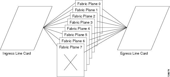
The multishelf system has eight fabric planes that support data traffic between the line cards. This figure shows a simplified view of the relationship between the line cards and fabric planes.
Each fabric plane is divided into three switching stages, which are numbered S1, S2, and S3. Data arrives at the S1 stage in an LCC, passes over the fabric cables to the S2 stage in a fabric card chassis (FCC), and then passes over the fabric cables again to the S3 stage in the destination LCC. This figure shows a simplified view of the relationship between the line cards and the fabric.
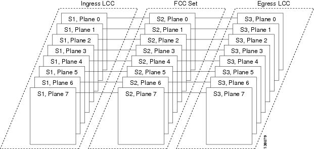
In each LCC, eight S13 fabric cards provide stages S1 and S3 for each of the eight fabric planes. All ingress traffic enters through the S1 component of the ingress S13 card, travels over the fabric cables and S2 fabric component, and exits through the S3 component on an S13 fabric card. Data traffic can enter through the S1 component of one card, pass through the S2 component, and then exit the S3 component of the same card.
The S2 cards are distributed between one, two, or four FCCs. The S2 cards for all fabric planes can be installed in a single FCC, but distributing the planes between FCCs prevents a failure in one FCC from disrupting traffic in all eight planes.
Fabric Card Chassis Switch Fabric Cards
There are three types of switch fabric cards: CRS-FCC-SFC for 40G CRS-1 multishelf systems, CRS-FCC-SFC-140 for CRS-3 multishelf systems, and CRS-FCC-SFC-400 for CRS-X multishelf systems. They provide the same functionality. The only difference between the three cards is capacity.
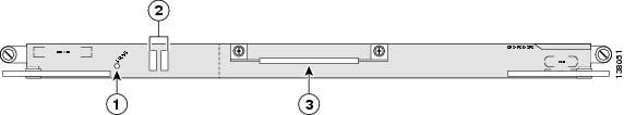
The front view of a CRS-FCC-SFC switch fabric card that is installed in a 40G multishelf system is shown in the below figure. The 140G FCC switch fabric card (CRS-FCC-SFC-140) and 400G FCC switch fabric card (CRS-FCC-SFC-400) are similar.
|
1 |
STATUS LED |
3 |
Handle |
|
2 |
Alphanumeric display |
|
|
Front-Panel LED Indicators
The front panel of the FCC SFC includes LED indicators that provide status and informational messages.
-
Status LED—Indicates the operational status of the SFC
- Green—Indicates that the SFC is functioning normally
- Yellow—Indicates a hardware or communication error
- Alphanumeric LED—Displays IOS XR messages
 Feedback