- Preparing for Broadband Access Aggregation
- Providing Protocol Support for Broadband Access Aggregation of PPPoE Sessions
- Providing Protocol Support for Broadband Access Aggregation of PPP over ATM Sessions
- Providing Connectivity Using ATM Routed Bridge Encapsulation over PVCs
- PPPoE Circuit-Id Tag Processing
- Providing Session Limit Support
- PPPoE Session Limit Local Override
- PPPoE - QinQ Support
- PPP-Max-Payload and IWF PPPoE Tag Support
- PPPoE Session Limiting on Inner QinQ VLAN
- PPPoE Agent Remote-ID and DSL Line Characteristics Enhancement
- Enabling PPPoE Relay Discovery and Service Selection Functionality
- Configuring Cisco Subscriber Service Switch Policies
- Per Session Queuing and Shaping for PPPoEoVLAN Using RADIUS
- 802.1P CoS Bit Set for PPP and PPPoE Control Frames
- PPPoE Smart Server Selection
- Monitoring PPPoE Sessions with SNMP
- PPPoE on ATM
- PPPoE on Ethernet
- PPP IP Unique Address and Prefix Detection
- Remote Access MPLS-VPNs
- Broadband High Availability Stateful Switchover
- Broadband High Availability In Service Software Upgrade
- Controlling Subscriber Bandwidth
- Offering PPPoE Clients a Selection of Services During Call Setup
Broadband Access Aggregation and DSL Configuration Guide, Cisco IOS XE Release 3S
Bias-Free Language
The documentation set for this product strives to use bias-free language. For the purposes of this documentation set, bias-free is defined as language that does not imply discrimination based on age, disability, gender, racial identity, ethnic identity, sexual orientation, socioeconomic status, and intersectionality. Exceptions may be present in the documentation due to language that is hardcoded in the user interfaces of the product software, language used based on RFP documentation, or language that is used by a referenced third-party product. Learn more about how Cisco is using Inclusive Language.
- Updated:
- February 5, 2009
Chapter: Remote Access MPLS-VPNs
- Finding Feature Information
- Contents
- Prerequisites for Remote Access MPLS-VPNs
- Restrictions for Remote Access MPLS-VPNs
- Information About Remote Access MPLS-VPNs
- How to Configure Remote Access MPLS-VPNs
- Configuration Examples for Remote Access MPLS-VPNs
- Additional References
- Feature Information for Remote Access MPLS-VPNs
- Glossary
Remote Access MPLS-VPNs
The Remote Access MPLS-VPNs feature allows the service provider to offer a scalable end-to-end Virtual Private Network (VPN) service to remote users. This feature integrates the Multiprotocol Label Switching (MPLS)-enabled backbone with broadband access capabilities.
Finding Feature Information
Your software release may not support all the features documented in this module. For the latest feature information and caveats, see the release notes for your platform and software release. To find information about the features documented in this module, and to see a list of the releases in which each feature is supported, see the "Feature Information for Remote Access MPLS-VPNs" section.
Use Cisco Feature Navigator to find information about platform support and Cisco software image support. To access Cisco Feature Navigator, go to http://www.cisco.com/go/cfn. An account on Cisco.com is not required.
Contents
•![]() Prerequisites for Remote Access MPLS-VPNs
Prerequisites for Remote Access MPLS-VPNs
•![]() Restrictions for Remote Access MPLS-VPNs
Restrictions for Remote Access MPLS-VPNs
•![]() Information About Remote Access MPLS-VPNs
Information About Remote Access MPLS-VPNs
•![]() How to Configure Remote Access MPLS-VPNs
How to Configure Remote Access MPLS-VPNs
•![]() Configuration Examples for Remote Access MPLS-VPNs
Configuration Examples for Remote Access MPLS-VPNs
•![]() Feature Information for Remote Access MPLS-VPNs
Feature Information for Remote Access MPLS-VPNs
Prerequisites for Remote Access MPLS-VPNs
The Remote Access MPLS-VPNs feature has the following prerequisites:
•![]() Your network must be running the following Cisco IOS XE services before you configure VPN operation:
Your network must be running the following Cisco IOS XE services before you configure VPN operation:
–![]() MPLS in the service provider backbone routers
MPLS in the service provider backbone routers
–![]() Tag Distribution Protocol (TDP) or the Label Distribution Protocol (LDP)
Tag Distribution Protocol (TDP) or the Label Distribution Protocol (LDP)
–![]() Border Gateway Protocol (BGP) in all routers providing a VPN service
Border Gateway Protocol (BGP) in all routers providing a VPN service
–![]() Cisco Express Forwarding switching in each MPLS-enabled router
Cisco Express Forwarding switching in each MPLS-enabled router
•![]() The provider edge (PE) routers that belong to the same VPN must be configured with the same VPN ID. The VPN ID must be unique to the service provider network.
The provider edge (PE) routers that belong to the same VPN must be configured with the same VPN ID. The VPN ID must be unique to the service provider network.
Restrictions for Remote Access MPLS-VPNs
The Remote Access MPLS-VPNs feature has the following restrictions:
•![]() The VPN ID is not used to control the distribution of routing information or to associate IP addresses.
The VPN ID is not used to control the distribution of routing information or to associate IP addresses.
Information About Remote Access MPLS-VPNs
•![]() Introduction to Remote Access MPLS-VPNs
Introduction to Remote Access MPLS-VPNs
•![]() PPP over Ethernet to MPLS VPN
PPP over Ethernet to MPLS VPN
Introduction to Remote Access MPLS-VPNs
MPLS-based VPNs allow service providers to deploy a scalable and cost-effective VPN service that provides a stable and secure path through the network. An enterprise connects to geographically dispersed sites in the Internet service provider's (ISPs) network through use of an MPLS backbone. Sites are interconnected to create an MPLS VPN.
The Remote Access MPLS-VPNs feature allows the service provider to offer a scalable end-to-end VPN service to remote users. The Remote Access MPLS-VPNs feature integrates the MPLS-enabled backbone with broadband access capabilities. By integrating access VPNs with MPLS VPNs, a service provider can:
•![]() Enable remote users and offices to seamlessly access their corporate networks
Enable remote users and offices to seamlessly access their corporate networks
•![]() Offer equal access to a set of different ISPs or retail service providers
Offer equal access to a set of different ISPs or retail service providers
•![]() Integrate their broadband access networks with the MPLS-enabled backbone
Integrate their broadband access networks with the MPLS-enabled backbone
•![]() Provide end-to-end VPN service to enterprise customers with remote access (RA) users and offices
Provide end-to-end VPN service to enterprise customers with remote access (RA) users and offices
•![]() Separate network access and connectivity functions from ISP functions
Separate network access and connectivity functions from ISP functions
MPLS VPN Architecture
MPLS VPN architecture enables the service provider to build the MPLS VPN network one time and add VPNs for new customers as needed, including them in the already established network. The elements that comprise the MPLS VPN are:
•![]() Customer edge (CE) routers—The routers to which subscribers in a customer's network connect. The CE router connects to a service provider's edge router (PE router). The CE router initiates the remote access session to the PE router.
Customer edge (CE) routers—The routers to which subscribers in a customer's network connect. The CE router connects to a service provider's edge router (PE router). The CE router initiates the remote access session to the PE router.
•![]() Provider edge (PE) routers—The routers located at the edge of the service provider's MPLS core network. The PE router connects to one or more CE routers and has full knowledge of the routes to the VPNs associated with those CE routers. The PE router does not have knowledge of the routes to VPNs whose associated CE routers are not connected to it.
Provider edge (PE) routers—The routers located at the edge of the service provider's MPLS core network. The PE router connects to one or more CE routers and has full knowledge of the routes to the VPNs associated with those CE routers. The PE router does not have knowledge of the routes to VPNs whose associated CE routers are not connected to it.
•![]() Provider (P) routers—The service provider routers that comprise the provider's core network. The P routers do not assign VPN information and they do not have any knowledge of CE routers. Instead, the main focus of the P router is on label switching.
Provider (P) routers—The service provider routers that comprise the provider's core network. The P routers do not assign VPN information and they do not have any knowledge of CE routers. Instead, the main focus of the P router is on label switching.
Figure 1 shows an example of MPLS VPN network architecture.
Figure 1 MPLS VPN Network—Example

PPP over Ethernet to MPLS VPN
Figure 2 shows the topology of integrated PPP over Ethernet (PPPoE) access to an MPLS VPN.
Figure 2 PPPoE Access to MPLS VPN Topology
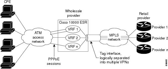
In Figure 2, the service provider operates an MPLS VPN that interconnects all customer sites. The service provider's core network is an MPLS backbone with VPN service capability. The service provider provides all remote access operations to its customer. The network-side interfaces are tagged interfaces, logically separated into multiple VPNs.
Remote access is provided using a PPPoE connection. In this model, when a remote user attempts to establish a connection with a corporate network, a PPPoE session is initiated and is terminated on the service provider's virtual home gateway (VHG) or PE router. All remote hosts connected to a particular CE router must be part of the VPN to which the CE router is connected.
The PPPoE to MPLS VPN architecture is a flexible architecture with the following characteristics:
•![]() A remote host can create multiple concurrent PPPoE sessions, each to a different VPN.
A remote host can create multiple concurrent PPPoE sessions, each to a different VPN.
•![]() If multiple remote hosts exist behind the same CE router, each remote host can log in to a different VPN.
If multiple remote hosts exist behind the same CE router, each remote host can log in to a different VPN.
•![]() Any remote host can log in to any VPN at any time because each VHG or PE router has the VRFs for all possible VPNs preinstantiated on it. This configuration requires that the VRF be applied through the RADIUS server, which can cause scalability issues.
Any remote host can log in to any VPN at any time because each VHG or PE router has the VRFs for all possible VPNs preinstantiated on it. This configuration requires that the VRF be applied through the RADIUS server, which can cause scalability issues.
The following events occur as the VHG or PE router processes the incoming PPPoE session:
1. ![]() A PPPoE session is initiated over the broadband access network.
A PPPoE session is initiated over the broadband access network.
2. ![]() The VHG/PE router accepts and terminates the PPPoE session.
The VHG/PE router accepts and terminates the PPPoE session.
3. ![]() The VHG/PE router obtains virtual access interface (VAI) configuration information:
The VHG/PE router obtains virtual access interface (VAI) configuration information:
–![]() The VHG/PE obtains a virtual template interface configuration information, which typically includes VRF mapping for sessions.
The VHG/PE obtains a virtual template interface configuration information, which typically includes VRF mapping for sessions.
–![]() The VHG/PE sends a separate request to either the customer's or service provider's RADIUS server for the VPN to authenticate the remote user.
The VHG/PE sends a separate request to either the customer's or service provider's RADIUS server for the VPN to authenticate the remote user.
–![]() The VPN's VRF instance is instantiated on the VHG or PE. The VPN's VRF contains a routing table and other information associated with a specific VPN.
The VPN's VRF instance is instantiated on the VHG or PE. The VPN's VRF contains a routing table and other information associated with a specific VPN.
Typically, the customer RADIUS server is located within the customer VPN. To ensure that transactions between the VHG/PE router and the customer RADIUS server occur over routes within the customer VPN, the VHG/PE router is assigned at least one IP address that is valid within the VPN.
4. ![]() The VHG/PE router forwards accounting records to the service provider's proxy RADIUS server, which in turn logs the accounting records and forwards them to the appropriate customer RADIUS server.
The VHG/PE router forwards accounting records to the service provider's proxy RADIUS server, which in turn logs the accounting records and forwards them to the appropriate customer RADIUS server.
5. ![]() The VHG/PE obtains an IP address for the CPE. The address is allocated from one of the following:
The VHG/PE obtains an IP address for the CPE. The address is allocated from one of the following:
–![]() Local address pool
Local address pool
–![]() Service provider's RADIUS server, which either specifies the address pool or directly provides the address
Service provider's RADIUS server, which either specifies the address pool or directly provides the address
–![]() Service provider's DHCP server
Service provider's DHCP server
6. ![]() The CPE is now connected to the customer VPN. Packets can flow to and from the remote user.
The CPE is now connected to the customer VPN. Packets can flow to and from the remote user.
How to Configure Remote Access MPLS-VPNs
To configure the RA to MPLS VPN feature, perform the following configuration tasks:
•![]() Configuring the MPLS Core Network (required)
Configuring the MPLS Core Network (required)
•![]() Configuring PPPoE (required)
Configuring PPPoE (required)
•![]() Configuring and Associating Virtual Private Networks (required)
Configuring and Associating Virtual Private Networks (required)
Configuring the MPLS Core Network
The MPLS core network is configured by enabling label switching of IP packets on interfaces, configuring virtual routing and forwarding instances, associating VRFs and configuring Multiprotocol BGP PE-to-PE routing sessions. For details relating to these activities, see the appropriate section of the Cisco IOS XE Multiprotocol Label Switching Configuration Guide.
Configuring PPPoE
To configure PPPoE, perform the following configuration tasks:
•![]() Configuring a Virtual Template Interface (required)
Configuring a Virtual Template Interface (required)
•![]() Configuring PPPoE in a Broadband Aggregation Group (required)
Configuring PPPoE in a Broadband Aggregation Group (required)
Configuring a Virtual Template Interface
To create and configure a virtual template interface that can be configured and applied dynamically in creating virtual access interfaces, perform the steps in the following task.
SUMMARY STEPS
1. ![]() enable
enable
2. ![]() configure terminal
configure terminal
3. ![]() interface virtual-template number
interface virtual-template number
4. ![]() ip unnumbered ethernet number
ip unnumbered ethernet number
5. ![]() ppp authentication chap
ppp authentication chap
6. ![]() ppp ipcp address required
ppp ipcp address required
DETAILED STEPS
Configuring PPPoE in a Broadband Aggregation Group
To configure a broadband aggregation (BBA) group for PPPoE and to link it to the appropriate virtual template interface, perform the steps in the following task.
SUMMARY STEPS
1. ![]() enable
enable
2. ![]() configure terminal
configure terminal
3. ![]() bba-group pppoe {name | global}
bba-group pppoe {name | global}
4. ![]() virtual-template template-number
virtual-template template-number
5. ![]() sessions per-mac limit per-mac-limit
sessions per-mac limit per-mac-limit
6. ![]() sessions max limit global pppoe session limit
sessions max limit global pppoe session limit
7. ![]() exit
exit
8. ![]() interface gigabitethernet slot/subslot/port.[subinterface]
interface gigabitethernet
slot/subslot/port.[subinterface]
9. ![]() encapsulation dot1q vlan-id
encapsulation dot1q vlan-id
10. ![]() pppoe enable [group group-name]
pppoe enable [group group-name]
DETAILED STEPS
Configuring and Associating Virtual Private Networks
A Virtual Private Network (VPN) service can be added to your MPLS configuration by configuring VPNs and associating the VPNs with a virtual template interface. For details relating to these activities, see the Configuring MPLS Layer 3 VPNs module.
Configuration Examples for Remote Access MPLS-VPNs
This section provides the following configuration example:
•![]() Example: Configuring Remote Access MPLS-VPNs with One VRF for PPPoE Sessions
Example: Configuring Remote Access MPLS-VPNs with One VRF for PPPoE Sessions
Example: Configuring Remote Access MPLS-VPNs with One VRF for PPPoE Sessions
The following example shows how to configure the RA to MPLS VPN feature with one VRF for PPPoE sessions:
!
!Enables the AAA access control model.
aaa new-model
!
!Configures AAA accounting.
aaa authentication login default none
aaa authentication enable default none
aaa authentication ppp default group radius
aaa authorization config-commands
aaa authorization network default local
aaa session-id common
enable password cisco
!
username pppoe password 0 pppoe
username common password 0 common
!
!Creates the common VRF.
ip vrf common
rd 100:1000
route-target export 100:1000
route-target import 100:1000
!
!Specifies the BBA group to be used to establish PPPoE sessions and specifies the maximum
!number of PPPoE sessions to be established over a vlan.
bba-group pppoe
virtual-template 1
sessions per-mac limit 32000
!
no virtual-template snmp
!
!Configures the small buffer.
buffers small permanent 15000
!
!Defines the general loopback interface used for reachability to the router and as a
!source IP address for sessions (IBGP, TDP, and so on).
interface Loopback0
ip address 10.16.3.1 255.255.255.255
ip ospf network point-to-point
!
!Creates a loopback interface in the vpn1 VRF. You do this for each customer VRF you IP
!unnumber interfaces to.
interface Loopback1
ip vrf forwarding vpn1
ip address 10.24.1.1 255.255.255.255
!
interface Loopback2
ip vrf forwarding vpn2
ip address 10.8.1.2 255.255.255.255
!
interface gigaethernet 0/0/0
load-interval 30
negotiation auto
no cdp enable
interface gigaethernet 0/0/0.9
encapsulation dot1q 9
pppoe enable
no cdp enable
!
!Enables label switching of IP packets on the interface.
interface GigabitEthernet1/0/0
ip address 10.1.10.1 255.255.0.0
no ip redirects
load-interval 30
negotiation auto
tag-switching ip
!
!Defines the virtual template and associates the common VRF with it.
interface Virtual-Template1
ip vrf forwarding common
ip unnumbered Loopback1
peer default ip address pool common
ppp authentication chap
!
!Configures OSPF to advertise the networks.
router ospf 100
log-adjacency-changes
auto-cost reference-bandwidth 1000
network 10.16.3.1 0.0.0.0 area 0
network 10.1.0.0 0.0.255.255 area 0
!
router rip
version 2
!
!Enters address family configuration mode to configure the VRF for PE to CE routing
!sessions.
address-family ipv4 vrf common
version 2
network 10.0.0.0
no auto-summary
exit-address-family
!
!Configures BGP to advertise the networks for the VPN.
router bgp 100
no synchronization
no bgp default ipv4-unicast
bgp log-neighbor-changes
neighbor 172.16.1.4 remote-as 100
neighbor 172.16.1.4 activate
!
!Enters address family configuration mode to configure the common VRF for PE to CE routing
!sessions.
address-family ipv4 vrf common
no auto-summary
no synchronization
aggregate-address 10.10.0.0 255.255.0.0 summary-only
exit-address-family
!
address-family vpnv4
neighbor 172.16.1.4 activate
neighbor 172.16.1.4 send-community both
exit-address-family
!
!Specifies the IP local pool to use for the VRF address assignment.
ip local pool common 10.10.1.1 10.10.126.0
ip classless
!Enters routing information in the routing table for the VRF.
ip route 10.0.0.0 255.0.0.0 FastEthernet0/0/0 10.9.0.1
ip route vrf common 10.22.0.0 255.255.0.0 Null0
ip route vrf common 10.30.0.0 255.255.0.0 2.1.1.1 3
ip route vrf common 10.32.0.0 255.255.0.0 2.2.151.1 2
ip route vrf common 10.33.0.0 255.255.0.0 2.3.101.1 2
no ip http server
ip pim bidir-enable
!
no cdp run
!
!Specifies the RADIUS host and configures RADIUS accounting. radius-server retransmit is
!on by default and cannot be removed.
radius-server host 10.19.100.150 auth-port 1645 acct-port 1646
radius-server retransmit 3
radius-server key test
radius-server authorization permit missing Service-Type
radius-server vsa send authentication
call admission limit 90
!
Additional References
Related Documents
|
|
|
|---|---|
Cisco IOS commands |
|
Description of commands associated with MPLS and MPLS applications |
|
Basic MPLS VPNs |
Standards
|
|
|
|---|---|
No new or modified standards are supported by this feature, and support for existing standards has not been modified by this feature. |
— |
MIBs
RFCs
|
|
|
|---|---|
No new or modified RFCs are supported by this feature, and support for existing RFCs has not been modified by this feature. |
— |
Technical Assistance
Feature Information for Remote Access MPLS-VPNs
Table 1 lists the release history for this feature.
Use Cisco Feature Navigator to find information about platform support and software image support. Cisco Feature Navigator enables you to determine which software images support a specific software release, feature set, or platform. To access Cisco Feature Navigator, go to http://www.cisco.com/go/cfn. An account on Cisco.com is not required.

Note ![]() Table 1 lists only the software release that introduced support for a given feature in a given software release train. Unless noted otherwise, subsequent releases of that software release train also support that feature.
Table 1 lists only the software release that introduced support for a given feature in a given software release train. Unless noted otherwise, subsequent releases of that software release train also support that feature.
Glossary
CE—customer edge.
PPPoE—Point-to-Point Protocol over Ethernet.
PE—provider edge.
 Feedback