- Preparing for Broadband Access Aggregation
- Providing Protocol Support for Broadband Access Aggregation of PPPoE Sessions
- Providing Protocol Support for Broadband Access Aggregation of PPP over ATM Sessions
- Providing Connectivity Using ATM Routed Bridge Encapsulation over PVCs
- PPPoE Circuit-Id Tag Processing
- Providing Session Limit Support
- PPPoE Session Limit Local Override
- PPPoE - QinQ Support
- PPP-Max-Payload and IWF PPPoE Tag Support
- PPPoE Session Limiting on Inner QinQ VLAN
- PPPoE Agent Remote-ID and DSL Line Characteristics Enhancement
- Enabling PPPoE Relay Discovery and Service Selection Functionality
- Configuring Cisco Subscriber Service Switch Policies
- Per Session Queuing and Shaping for PPPoEoVLAN Using RADIUS
- 802.1P CoS Bit Set for PPP and PPPoE Control Frames
- PPPoE Smart Server Selection
- Monitoring PPPoE Sessions with SNMP
- PPPoE on ATM
- PPPoE on Ethernet
- PPP IP Unique Address and Prefix Detection
- Remote Access MPLS-VPNs
- Broadband High Availability Stateful Switchover
- Broadband High Availability In Service Software Upgrade
- Controlling Subscriber Bandwidth
- Offering PPPoE Clients a Selection of Services During Call Setup
Broadband Access Aggregation and DSL Configuration Guide, Cisco IOS XE Release 3S
Bias-Free Language
The documentation set for this product strives to use bias-free language. For the purposes of this documentation set, bias-free is defined as language that does not imply discrimination based on age, disability, gender, racial identity, ethnic identity, sexual orientation, socioeconomic status, and intersectionality. Exceptions may be present in the documentation due to language that is hardcoded in the user interfaces of the product software, language used based on RFP documentation, or language that is used by a referenced third-party product. Learn more about how Cisco is using Inclusive Language.
- Updated:
- November 24, 2010
Chapter: Providing Connectivity Using ATM Routed Bridge Encapsulation over PVCs
- Finding Feature Information
- Contents
- Prerequisites for Providing Connectivity Using ATM Routed Bridge Encapsulation over PVCs
- Restrictions for Providing Connectivity Using ATM Routed Bridge Encapsulation over PVCs
- Information About Providing Connectivity Using ATM Routed Bridge Encapsulation over PVCs
- How to Configure ATM Routed Bridge Encapsulation over PVCs
- Configuration Examples for Providing Connectivity Using ATM Routed Bridge Encapsulation
- Additional References
- Feature Information for Providing Connectivity Using ATM Routed Bridge Encapsulation
Providing Connectivity Using ATM Routed Bridge Encapsulation over PVCs
The Providing Connectivity Using ATM Routed Bridge Encapsulation over PVCs feature provides the functionality of bridged ATM interface support to ATM switched virtual circuits (SVCs). Unlike permanent virtual circuits (PVCs), SVCs must be triggered by ongoing traffic and can be brought down when idle for some time. The SVCs are triggered, if down, and the traffic is passed on to the SVCs belonging to bridged ATM interface.
ATM routed bridge encapsulation (RBE) is used to route IP over bridged RFC 1483 Ethernet traffic from a stub-bridged LAN.
Finding Feature Information
Your software release may not support all the features documented in this module. For the latest feature information and caveats, see the release notes for your platform and software release. To find information about the features documented in this module, and to see a list of the releases in which each feature is supported, see the "Feature Information for Providing Connectivity Using ATM Routed Bridge Encapsulation" section.
Use Cisco Feature Navigator to find information about platform support and Cisco software image support. To access Cisco Feature Navigator, go to http://www.cisco.com/go/cfn. An account on Cisco.com is not required.
Contents
•![]() Prerequisites for Providing Connectivity Using ATM Routed Bridge Encapsulation over PVCs
Prerequisites for Providing Connectivity Using ATM Routed Bridge Encapsulation over PVCs
•![]() Restrictions for Providing Connectivity Using ATM Routed Bridge Encapsulation over PVCs
Restrictions for Providing Connectivity Using ATM Routed Bridge Encapsulation over PVCs
•![]() Information About Providing Connectivity Using ATM Routed Bridge Encapsulation over PVCs
Information About Providing Connectivity Using ATM Routed Bridge Encapsulation over PVCs
•![]() How to Configure ATM Routed Bridge Encapsulation over PVCs
How to Configure ATM Routed Bridge Encapsulation over PVCs
•![]() Configuration Examples for Providing Connectivity Using ATM Routed Bridge Encapsulation
Configuration Examples for Providing Connectivity Using ATM Routed Bridge Encapsulation
•![]() Feature Information for Providing Connectivity Using ATM Routed Bridge Encapsulation
Feature Information for Providing Connectivity Using ATM Routed Bridge Encapsulation
Prerequisites for Providing Connectivity Using ATM Routed Bridge Encapsulation over PVCs
•![]() When ATM SVCs are used, support for a form of bridging, such as integrated routing and bridging, is required.
When ATM SVCs are used, support for a form of bridging, such as integrated routing and bridging, is required.
•![]() Before configuring connectivity from a remote bridged Ethernet network to a routed network using ATM routed bridge encapsulation, you must understand the concepts in the Understanding Broadband Access Aggregation module.
Before configuring connectivity from a remote bridged Ethernet network to a routed network using ATM routed bridge encapsulation, you must understand the concepts in the Understanding Broadband Access Aggregation module.
Restrictions for Providing Connectivity Using ATM Routed Bridge Encapsulation over PVCs
•![]() Unlike PVCs, SVCs must be triggered by ongoing traffic and might be brought down after they have been idle for some time. The Bridged 1483 Encapsulated Traffic over ATM SVCs feature allows for the SVC to be triggered if down, and to pass the traffic on to the SVCs belonging to the bridged ATM interface.
Unlike PVCs, SVCs must be triggered by ongoing traffic and might be brought down after they have been idle for some time. The Bridged 1483 Encapsulated Traffic over ATM SVCs feature allows for the SVC to be triggered if down, and to pass the traffic on to the SVCs belonging to the bridged ATM interface.
•![]() ATM RBE does not support MAC-layer access lists; only IP access lists are supported.
ATM RBE does not support MAC-layer access lists; only IP access lists are supported.
Information About Providing Connectivity Using ATM Routed Bridge Encapsulation over PVCs
•![]() Overview on Bridged 1483 Encapsulated Traffic over ATM SVCs
Overview on Bridged 1483 Encapsulated Traffic over ATM SVCs
•![]() ATM RBE Subinterface Grouping by PVC Range
ATM RBE Subinterface Grouping by PVC Range
•![]() ATM RBE Subinterface Grouping by PVC Range
ATM RBE Subinterface Grouping by PVC Range
•![]() DHCP Option 82 Support for RBE
DHCP Option 82 Support for RBE
•![]() DHCP Lease Limit per ATM RBE Unnumbered Interface
DHCP Lease Limit per ATM RBE Unnumbered Interface
•![]() Benefits of Providing Connectivity Using ATM Routed Bridge Encapsulation
Benefits of Providing Connectivity Using ATM Routed Bridge Encapsulation
Overview on Bridged 1483 Encapsulated Traffic over ATM SVCs
ATM RBE is used to route IP over bridged RFC 1483 Ethernet traffic from a stub-bridged LAN.
Figure 1 shows an ATM subinterface on a headend router that is configured to function in ATM routed-bridge encapsulation mode. This configuration is useful when a remote bridged Ethernet network device needs connectivity to a routed network via a device bridging from an Ethernet LAN to an ATM RFC 1483 bridged encapsulation.
Figure 1 ATM Routed Bridge Encapsulation
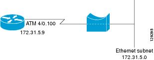
Because PVCs are statically configured along the entire path between the end systems, it would not be suitable to route bridged encapsulated traffic over them when the user wants to configure the virtual circuits (VCs) dynamically and tear down the VCs when there is no traffic.
ATM RBE Subinterface Grouping by PVC Range
You can configure ATM routed bridge encapsulation using an ATM PVC range rather than individual PVCs. When you configure a PVC range for routed bridge encapsulation, a point-to-point subinterface is created for each PVC in the range. The number of PVCs in a range can be calculated using the following formula:
number of PVCs = (end-vpi - start-vpi + 1) x (end-vci - start-vci +1)
Subinterface numbering begins with the subinterface on which the PVC range is configured and increases sequentially through the range.

Note ![]() You cannot explicitly configure the individual point-to-point subinterfaces created by the PVC range on a point-to-point subinterface. All the point-to-point subinterfaces in the range share the same configuration as the subinterface on which the PVC range is configured.
You cannot explicitly configure the individual point-to-point subinterfaces created by the PVC range on a point-to-point subinterface. All the point-to-point subinterfaces in the range share the same configuration as the subinterface on which the PVC range is configured.
DHCP Option 82 Support for RBE
The DHCP relay agent information option (option 82) enables a Dynamic Host Configuration Protocol (DHCP) relay agent to include information about itself when forwarding client-originated DHCP packets to a DHCP server. The DHCP server can use this information to implement IP address or other parameter-assignment policies.
The DHCP Option 82 Support for RBE feature provides support for the DHCP relay agent information option when ATM RBE is used. Figure 2 shows a typical network topology in which ATM RBE and DHCP are used. The aggregation router that is using ATM RBE is also serving as the DHCP relay agent.
Figure 2 Network Topology Using ATM RBE and DHCP
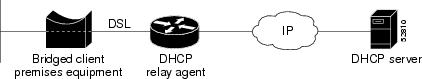
This feature communicates information to the DHCP server using a suboption of the DHCP relay agent information option called agent remote ID. The information sent in the agent remote ID includes an IP address identifying the relay agent and information about the ATM interface and the PVC over which the DHCP request came in. The DHCP server can use this information to make IP address assignments and security policy decisions.
Figure 3 shows the format of the agent remote ID suboption.
Figure 3 Format of the Agent Remote ID Suboption
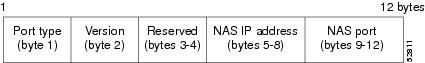
Table 1 describes the agent remote ID suboption fields displayed in Figure 3.
|
|
|
|---|---|
Port Type |
Port type. The value 0x01 indicates RBE. (1 byte) |
Version |
Option 82 version. The value 0x01 specifies the RBE version of Option 82 (1 byte). |
Reserved |
RBE reserved (2 bytes). |
NAS IP Address |
One of the interfaces on the DHCP relay agent. The rbe nasip command can be used to specify which IP address will be used. (4 bytes) |
NAS Port |
RBE-enabled virtual circuit on which the DHCP request has come in. See Figure 4 for the format of this field. (4 bytes) |
Figure 4 shows the format of the network access server (NAS) port field in the agent remote ID suboption.
Figure 4 Format of the NAS Port Field
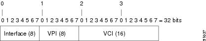
Figure 5 shows the format of the interface field. If there is no module, the value of the module bit is 0.
Figure 5 Format of the Interface Field

DHCP Lease Limit per ATM RBE Unnumbered Interface
The DHCP lease limit per ATM RBE Unnumbered Interface feature is enabled on a Cisco IOS DHCP relay agent connected to clients through unnumbered interfaces. The relay agent keeps information about the DHCP leases offered to the clients per subinterface. When a DHCPACK message is forwarded to the client, the relay agent increments the number of leases offered to clients on that subinterface. If a new DHCP client tries to obtain an IP address and the number of leases has already reached the configured lease limit, DHCP messages from the client will be dropped and will not be forwarded to the DHCP server.
If this feature is enabled on the Cisco IOS DHCP server directly connected to clients through unnumbered interfaces, the server allocates addresses and increments the number of leases per subinterface. If a new client tries to obtain an IP address, the server will not offer an IP address if the number of leases on the subinterface has already reached the configured lease limit.
Benefits of Providing Connectivity Using ATM Routed Bridge Encapsulation
Bridged IP packets received on an ATM interface configured in routed-bridge mode are routed via the IP header. Such interfaces take advantage of the characteristics of a stub LAN topology commonly used for digital subscriber line (DSL) access and offer increased performance and flexibility over integrated routing and bridging (IRB).
Another benefit of ATM RBE is that it reduces the security risk associated with normal bridging or IRB by reducing the size of the nonsecured network. By using a single VC allocated to a subnet (which could be as small as a single IP address), ATM RBE uses an IP address in the subnet to limit the "trust environment" to the premises of a single customer.
ATM RBE supports Cisco Express Forwarding (CEF), fast switching, and process switching.
The DHCP Option 82 Support for RBE feature enables those service providers to use DHCP to assign IP addresses and DHCP option 82 to implement security and IP address assignment policies.
The DHCP Lease Limit per ATM RBE Unnumbered Interface feature allows an Internet service provider (ISP) to globally limit the number of leases available to clients per household or connection.
How to Configure ATM Routed Bridge Encapsulation over PVCs
This section contains the following procedures:
•![]() Configuring ATM Routed Bridge Encapsulation Using PVCs (required)
Configuring ATM Routed Bridge Encapsulation Using PVCs (required)
•![]() Configuring DHCP Option 82 for RBE (required)
Configuring DHCP Option 82 for RBE (required)
•![]() Configuring the DHCP Lease Limit (required)
Configuring the DHCP Lease Limit (required)
•![]() Troubleshooting the DHCP Lease Limit (optional)
Troubleshooting the DHCP Lease Limit (optional)
Configuring ATM Routed Bridge Encapsulation Using PVCs
Perform the following task to configure ATM RBE using PVCs. Only the specified network layer (IP) is routed. Any remaining protocols can be passed on to bridging or other protocols. In this manner, ATM RBE can be used to route IP, while other protocols (such as IPX) are bridged normally.
SUMMARY STEPS
1. ![]() enable
enable
2. ![]() configure terminal
configure terminal
3. ![]() interface atm slot/0.subinterface-number point-to-point
interface atm slot/0.subinterface-number point-to-point
4. ![]() pvc vpi/vci
pvc vpi/vci
or
range [range-name] pvc start-vpi/start-vci end-vpi/end-vci
5. ![]() exit
exit
6. ![]() ip address ip-address mask [secondary]
ip address ip-address mask [secondary]
7. ![]() end
end
8. ![]() show arp
show arp
or
show ip cache verbose
DETAILED STEPS
Examples
To confirm that ATM RBE is enabled, use the show arp command and the show ip cache verbose command in privileged EXEC mode:
Router# show arp
Protocol Address Age (min) Hardware Addr Type Interface
Internet 209.165.201.51 6 0001.c9f2.a81d ARPA Ethernet3/1
Internet 209.165.201.49 - 0060.0939.bb55 ARPA Ethernet3/1
Internet 209.165.202.128 30 0010.0ba6.2020 ARPA Ethernet3/0
Internet 209.165.201.52 6 00e0.1e8d.3f90 ARPA ATM1/0.4
Internet 209.165.201.53 5 0007.144f.5d20 ARPA ATM1/0.2
Internet 209.165.202.129 - 0060.0939.bb54 ARPA Ethernet3/0
Internet 209.165.201.125 30 00b0.c2e9.bc55 ARPA Ethernet3/1#
Router# show ip cache verbose
IP routing cache 3 entries, 572 bytes
9 adds, 6 invalidates, 0 refcounts
Minimum invalidation interval 2 seconds, maximum interval 5 seconds,
quiet interval 3 seconds, threshold 0 requests
Invalidation rate 0 in last second, 0 in last 3 seconds
Last full cache invalidation occurred 00:30:34 ago
Prefix/Length Age Interface Next Hop
209.165.201.51/32-24 00:30:10 Ethernet3/1 10.1.0.51 14 0001C9F2A81D00600939 BB550800
209.165.202.129/32-24 00:00:04 ATM1/0.2 	10.8.100.50 28
00010000AAAA030080C2000700000007144F5D2000600939 BB1C0800
209.165.201.125/32-24 00:06:09 ATM1/0.4 	10.8.101.35 28
00020000AAAA030080C20007000000E01E8D3F9000600939 BB1C0800
Configuring DHCP Option 82 for RBE
Perform this task to configure the DHCP Option 82 Support for RBE feature.
Prerequisites for Configuring DHCP Option 82 for RBE
DHCP option 82 support must be configured on the DHCP relay agent using the ip dhcp relay information option command before you can use the DHCP Option 82 Support for RBE feature.
SUMMARY STEPS
1. ![]() enable
enable
2. ![]() configure terminal
configure terminal
3. ![]() ip dhcp relay information option
ip dhcp relay information option
4. ![]() rbe nasip source-interface
rbe nasip source-interface
5. ![]() end
end
DETAILED STEPS
Configuring the DHCP Lease Limit
Perform this task to limit the number of DHCP leases allowed on ATM RBE unnumbered or serial unnumbered interfaces.
SUMMARY STEPS
1. ![]() enable
enable
2. ![]() configure terminal
configure terminal
3. ![]() ip dhcp limit lease per interface lease-limit
ip dhcp limit lease per interface lease-limit
4. ![]() end
end
DETAILED STEPS
Troubleshooting the DHCP Lease Limit
Perform this task to troubleshoot the DHCP lease limit.
SUMMARY STEPS
1. ![]() enable
enable
2. ![]() debug ip dhcp server packet
debug ip dhcp server packet
3. ![]() debug ip dhcp server events
debug ip dhcp server events
DETAILED STEPS
Configuration Examples for Providing Connectivity Using ATM Routed Bridge Encapsulation
The following examples show various ways to provide connectivity from a remote bridged network to a routed network using ATM RBE.
•![]() Example: Configuring ATM RBE on PVCs
Example: Configuring ATM RBE on PVCs
•![]() Example: Configuring ATM RBE on an Unnumbered Interface
Example: Configuring ATM RBE on an Unnumbered Interface
•![]() Example: Concurrent Bridging and ATM RBE
Example: Concurrent Bridging and ATM RBE
•![]() Example: DHCP Option 82 for RBE Configuration
Example: DHCP Option 82 for RBE Configuration
Example: Configuring ATM RBE on PVCs
The following example shows a typical ATM routed bridge encapsulation configuration:
enable
configure terminal
interface atm 4/0.100 point-to-point
ip address 209.165.200.225 255.255.255.224
pvc 0/32
end
Example: Configuring ATM RBE on an Unnumbered Interface
The following example uses a static route to point to an unnumbered interface:
enable
configure terminal
interface loopback 0
ip address 209.165.200.226 255.255.255.224
interface atm 4/0.100 point-to-point
ip unnumbered loopback 0
pvc 0/32
atm route-bridge ip
exit
ip route 209.165.200.228 255.255.255.224 atm 4/0.100
end
Example: Concurrent Bridging and ATM RBE
The following example shows concurrent use of ATM RBE with normal bridging. IP datagrams are route-bridged, and other protocols (such as IPX or AppleTalk) are bridged.
bridge 1 protocol ieee
interface atm 4/0.100 point-to-point
ip address 209.165.200.225 255.255.255.224
pvc 0/32
bridge-group 1
atm route-bridge ip
Example: DHCP Option 82 for RBE Configuration
In the following example, DHCP option 82 support is enabled on the DHCP relay agent using the ip dhcp relay information option command. The rbe nasip command configures the router to forward the IP address for Loopback0 to the DHCP server.
ip dhcp-server 209.165.200.225
!
ip dhcp relay information option
!
interface Loopback0
ip address 209.165.201.0 255.255.255.248
!
interface atm 4/0
no ip address
!
interface atm 4/0.1 point-to-point
ip unnumbered Loopback0
ip helper-address 209.165.201.3
atm route-bridged ip
pvc 88/800
encapsulation aal5snap
!
!
interface Ethernet5/1
ip address 209.165.201.4 255.255.255.248
!
router eigrp 100
network 209.165.201.0
network 209.165.200.0
!
rbe nasip Loopback0
For the configuration example, the value (in hexadecimal) of the agent remote ID suboption would be 010100000B01018140580320. Table 2 shows the value of each field within the agent remote ID suboption.
Example: DHCP Lease Limit
In the following example, if more than three clients try to obtain an IP address from interface ATM4/0.1, the DHCPDISCOVER packets will not be forwarded to the DHCP server. If the DHCP server resides on the same router, DHCP will not reply to more than three clients.
ip dhcp limit lease per interface 3
!
interface loopback0
ip address 209.165.201.3 255.255.255.248
!
interface atm 4/0.1
no ip address
!
interface atm 4/0.1 point-to-point
ip helper-address 172.16.1.2
ip unnumbered loopback0
atm route-bridged ip
pvc 88/800
encapsulation aal5snap
Additional References
Related Documents
|
|
|
|---|---|
Cisco IOS commands |
|
Broadband Access Aggregation and DSL commands |
Cisco IOS Broadband Access Aggregation and DSL Command Reference |
Broadband access aggregation concepts |
|
Preparing for broadband access aggregation task |
|
DHCP commands |
|
DHCP configuration tasks |
"Configuring the Cisco IOS DHCP Server" module in the Cisco IOS IP Addressing Services Configuration Guide |
Standards
|
|
|
|---|---|
None |
— |
MIBs
|
|
|
|---|---|
None |
To locate and download MIBs for selected platforms, Cisco software releases, and feature sets, use Cisco MIB Locator found at the following URL: |
RFCs
|
|
|
|---|---|
None |
— |
Technical Assistance
Feature Information for Providing Connectivity Using ATM Routed Bridge Encapsulation
Table 3 lists the features in this module and provides links to specific configuration information.
Use Cisco Feature Navigator to find information about platform support and software image support. Cisco Feature Navigator enables you to determine which software images support a specific software release, feature set, or platform. To access Cisco Feature Navigator, go to http://www.cisco.com/go/cfn. An account on Cisco.com is not required.
Table 3 lists only the software release that introduced support for a given feature in a given software release train. Unless noted otherwise, subsequent releases of that software release train also support that feature.
|
|
|
|
|---|---|---|
Bridged 1483 Encapsulated Traffic over ATM SVCs |
12.4(15)T |
The Bridged 1483 Encapsulated Traffic over ATM SVCs feature provides support for bridged 1483 encapsulated packets to trigger ATM SVC and also support for sending this traffic on triggered ATM SVCs. The following section provides information about this feature: • |
DHCP Option 82 Support for Routed Bridge Encapsulation |
15.1(1)S |
This feature provides support for the DHCP relay agent information option when ATM RBE is used. The following sections provide information about this feature: • • The following command was introduced: |
DHCP Lease Limit per ATM RBE Unnumbered Interface |
12.3(2)T |
This feature limits the number of DHCP leases per subinterface offered to DHCP clients connected from an ATM RBE unnumbered interface or serial unnumbered interface of the DHCP server or DHCP relay agent. The following sections provide information about this feature: • • The following command was introduced: |
 Feedback