Cisco MDS 9500 End-of-Support and Next Steps
Available Languages
Bias-Free Language
The documentation set for this product strives to use bias-free language. For the purposes of this documentation set, bias-free is defined as language that does not imply discrimination based on age, disability, gender, racial identity, ethnic identity, sexual orientation, socioeconomic status, and intersectionality. Exceptions may be present in the documentation due to language that is hardcoded in the user interfaces of the product software, language used based on RFP documentation, or language that is used by a referenced third-party product. Learn more about how Cisco is using Inclusive Language.
- US/Canada 800-553-2447
- Worldwide Support Phone Numbers
- All Tools
 Feedback
 Feedback
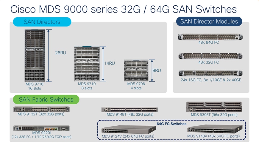
Over the last year, Cisco has released multiple 64G Fibre channel capabilities for the Cisco MDS 9000 Series modular and fabric switches. These new 64G-capable innovations have many unique industry enhancements like Dynamic Congestion Prevention with Cisco Dynamic Ingress Rate Limiting (DIRL), the industry's first on-chip analytics for NVMe, and FC-SCSI packets, built-in Anti-counterfeit technology using secure boot, and many more.
With these new Cisco MDS innovations released and in market, customers are prompted to upgrade their existing MDS 9500 hardware to the new generation of MDS 32G/64G hardware.
To help these customers properly retire their MDS 9500 hardware, we are providing the information listed below to assist with the disposal of the hardware securely and safely with minimal environmental impact.
The guidance provided in this document should be followed when phasing out of the end of life Cisco MDS 9000 series director switch or fabric switch from an active fabric.
Before starting the retiring process, a good set of planning will help reduce any disruption during execution. Let us have a proper planning on how what, and when to do it. We have some best practices, recommended steps, and so on to help you with the planning stage.
Recommendations:
1. Verify active dual path redundancy (multipathing) between every initiator (server) and target (storage) devices. The Dual Host path redundancy check feature in DCNM (Data Center Network Manager) / NDFC (Nexus Dashboard Fabric Controller) may be used to accomplish this.
2. Verify any hardware or software errors on all the switches in the fabric.
3. The process should be performed on a single fabric at a time. This will ensure a smoother transition to the new switch.
4. Have console connectivity using a console port to all of the switches in the fabric. This ensures access to the switch if anything goes wrong during the process.
Best practices:
1. All changes need a peer review for all stages of the change plan covering the planning, preparation, execution, and backout steps.
2. All change plans should have a stop check with storage and SAN administrators to confirm the process is being followed the right way.
3. All change plans should include the approval groups for the technical teams that have devices connected to the SAN fabric.
4. All change plans should have a clear backout plan.
5. Capture a show tech-support details from all the switches in the fabric to one of the SFTP/DCNM servers.
6. Clear the error logs on all switches in the fabric to create a baseline.
7. Backup all switch configurations across the fabric.
8. Prepare a list of all ISLs, aliases, VSANs, zoning configurations, and so on.
Following is a suggested planning phase of the retiring process.
Step 1. Log in to the switch from CLI.
Step 2. Verify that there are no Segmented VSANs.
CLI commands:
List all ISLs.
show topology
Then for each ISL listed:
show interface <interface name>
ensure all VSANs are ‘Up’ and not ‘isolated’ or ‘initializing’.
Step 3. Verify that there are no module failures.
CLI command:
show module
Step 4. Verify the status of supervisor modules as "Active" and "Standby"
show system redundancy status
Step 5. Verify the zoning status (Basic/enhanced/smart zone).
CLI command:
show zone status
Step 6. Check Cisco Fabric services (CFS) lock.
CLI command:
show zone status
Step 7. Backing up existing switch configurations: It is recommended to back up the existing configuration before retiring it. This will help us revert the process if needed at any stage in this operation.
CLI commands:
switch#copy running-config startup-config
switch#copy running-config sftp
switch#copy running-config ftp
To start the retiring process, here is the step-by-step process. All changes or commands will be executed on the switch to be retired.
Select a new principal switch: If you are planning to retire the existing principal switch, the new principal switch needs to be elected before retiring the existing one, for each VSAN. Otherwise, the fabric will elect a new principal switch after the E ports are shut down, and the fabric will no longer see the existing principal switch as part of the fabric for every VSAN. Selecting a principal switch for every VSAN is a key step in the planning stage. These steps should be performed for every VSAN where the switch currently being retired is principal. More details on selecting a principal switch are mentioned in the following section:
Selecting Principal switch
A new switch will have to be configured with a higher priority (range is from 1 – 254, 1 being the highest), followed by a non-disruptive domain restart. It is required for the configuration to be effective. It is also preferred to have a priority set for another core switch as 3 to always remain in desired state if a failure happens.
1. Find the CURRENT domain-id and principal switch in the fabric for the local switch. Use the below command to find how many switches are part of the fabric as well as the domain IDs and role of the switch.
CLI command:
show fcdomain domain-list vsan <vsan_number>
2. Now, make the domain-ids static on ALL switches in the fabric, matching the output with the domain-id from the above command. This is for every VSAN.
CLI command:
switch(config)# fcdomain domain <domain-id from above> static vsan <vsan #>
3. On the switch you want to make principal, reduce the priority to a low value such as 1.
CLI command:
switch(config)# fcdomain priority 1 vsan <vsan #>
4. On the switch that you want to make principal, RESTART FC DOMAIN, non-disruptively:
CLI command:
switch(config)# fcdomain restart vsan <vsan #>
Note: The current and configured domain ID must match the change in the above step to be non-disruptive.
5. Save the configuration
CLI command:
switch#copy run start
6. Verify if the switch is part of any IVR (Inter-VSAN routing) topology. If the switch is part of IVR topology, remove IVR configuration from the switch. Make sure the switch is not part of any active IVR configuration. Removing the IVR config will also remove the IVR zoning configuration as it is part of the IVR configuration. Remove any sWWN configuration as well. sWWN is the WWN for the switch. If there is no sWWN provided, switch will automatically use local sWWN.
CLI commands:
switch# show ivr vsan-topology
switch(config)# no ivr distribute
switch(config)# ivr commit (may not be needed if CFS lock is disabled)
switch(config)# no feature ivr
7. Disabling zoning lock on switch: If the zoning lock is issued to on a switch, the lock has to be cleared forcefully, issue no commit with the force flag.
CLI commands:
switch(config)# no zone commit vsan <vsan_id> force
switch# clear zone lock vsan <vsan_id>
switch-2# clear zone lock vsan <vsan_id>
8. Confirm that lock has been cleared
CLI command:
switch-2# show zone status vsan <vsan_id>
9. Shut down “F” ports on the switch connected to the end devices (hosts and storage)
CLI commands:
switch#configure terminal
switch(config)#int fc(number to number)
Switch(config)#shut
10. Shut down the “E” ports on switch, connected to ISLs.
CLI commands:
switch#configure terminal
switch(config)#int fc(number to number)
switch(config)#shut
11. Disconnect the FC cables.
12. Delete zones and zonesets
CLI command:
clear zone database <vsan_id>
13. Delete each vsan manually
CLI commands:
switch#configure terminal
switch(config)#vsan database
switch(config)#no vsan <vsan_id>
switch(config)#no vsan <vsan_id>
14. Verify device alias distribution, and disable it:
CLI commands:
switch#show device-alias status
switch(config)#no device-alias distribute
15. Verify and delete device alias database
CLI command:
switch(config)#clear device-alias database
16. Purging is not required if you are removing only one switch, but if you are retiring multiple switches, purging may be required from the Fabric manager / DCNM / NDFC to remove them completely. If purging is required, perform the following steps:
Step 1. Click Switches in the Physical Attributes pane.
Step 2. Right-click the device in the table.
Step 3. Select Purge to purge the switches in Fabric manager.
If there is an issue, restore the switch configuration from the backup taken in the previous steps.
1. Establish a console connection to the switch being sanitized.
2. Perform configuration wipeout on the switch. This command will erase the boot variables and the IP configuration of management interface and reboot the switch.
CLI Commands:
switch#write erase
switch#write erase boot
3. Optional: Perform Secure erase (for devices running NX-OS 9.x or later release):
CLI command:
switch#factory-reset
Note: Please make sure to read and understand the Secure erase process before executing it: https://www.cisco.com/c/en/us/td/docs/dcn/mds9000/sw/9x/configuration/fundamentals/cisco-mds-9000-nx-os-fundamentals-configuration-guide-9x/basic_device_management.html#Cisco_Concept.dita_ac0d7df9-ef53-4fde-a7f2-e4065e1cc619
If the switch comes up at the command prompt after executing the write erase boot or factory-reset command, the switch is reset and set to factory defaults.
And lastly: Recycle responsibly.
Extending the product lifecycle is a Cisco priority. We follow circular economy principles to reuse, remanufacture, and refurbish what we can. But when products reach their end-of-life, the Product Recycling program steps in with certified contracted recyclers.
Our programs
Helping customers and partners
Cisco's recycling program recently rebranded as Customer Recycling Solutions (CRS), enables customers to return end-of-life equipment to Cisco at no cost. The CRS program also enables easy returns for partners not using the Takeback Incentive or the Exceptional Pick Up Program (EPUP).
Supporting our partners
The Global Scrap Program assists Cisco contracted repair manufacturers, distribution depots, demo loan returns, and distributor stock rotations with effective and environmentally responsible global recycling and collection processes.
• Generate Global Scrap request