Cisco Validated Design for Data Center Networking Blueprint for AI/ML Applications
Available Languages
Bias-Free Language
The documentation set for this product strives to use bias-free language. For the purposes of this documentation set, bias-free is defined as language that does not imply discrimination based on age, disability, gender, racial identity, ethnic identity, sexual orientation, socioeconomic status, and intersectionality. Exceptions may be present in the documentation due to language that is hardcoded in the user interfaces of the product software, language used based on RFP documentation, or language that is used by a referenced third-party product. Learn more about how Cisco is using Inclusive Language.
- US/Canada 800-553-2447
- Worldwide Support Phone Numbers
- All Tools
 Feedback
 Feedback
Building a Non-Blocking Network
Building a Lossless Ethernet Fabric Using RoCEv2 As The Transport
Using NDFC to Build Your AI/ML Network
Versions of Software Used in This Validated Design
This Cisco Validated Design (CVD) document provides tested configurations for the Data Center Networking Blueprint for AI/ML Applications document. CLI configurations for the network devices, as well as examples for configuring the network fabric using the Cisco Nexus Dashboard Fabric Controller (NDFC) are provided. The aim of this CVD is to build a non-blocking, low latency, lossless ethernet network for AI/ML workloads. As discussed in the blueprint document, to build a lossless Ethernet network, the endpoints must participate in the quality of service (QoS) configuration. That means that the endpoints must understand both explicit congestion notifications (ECN) as well as priority flow control (PFC). The configuration required for the endpoints to work with ECN and PFC is not in the scope of this document. To configure ECN and PFC for endpoints, consult the vendor's documentation.
Building a Non-Blocking Network
For the examples used in this CVD, we are building a two-tier, spine switch-leaf switch design to provide the lowest latency and scalability. We are building this network to accommodate 128 servers each with 2 x 100G ports. This means that 256 x 100G ports are required at the leaf layer for server connectivity. To make this a non-blocking network, the uplinks to the spine switches must have the same bandwidth capacity as the front panel server-facing ports. To accommodate the requirements for the leaf layer, this example uses the Cisco Nexus 93600CD-GX switch. The Cisco Nexus 93600CD-GX switch has 28 ports of 100G that we can use as server ports and 8 uplinks of 400G. This combination of server-facing and uplink ports makes this a non-blocking switch. To connect all 256 ports, we need 10 leaf switches. Servers will be dual homed to two separate leaf switches to provide network redundancy and sufficient bandwidth. This design ensures there are free ports available to connect to storage devices, or storage clusters, and to connect this AI/ML server cluster to other parts of the enterprise network.
To accommodate the amount of bandwidth coming from the leaf switches, we need 80 x 400G ports. For redundancy reasons, we can choose 2 spine switches, but as scale and resiliency are crucial for AI/ML workloads, we will build the system with four spine switches. This example uses the Cisco Nexus 9332D-GX2B switch for the spine switch. The spine switches will each connect 20 x 400G ports. This leaves 12 ports free on each spine switch, so additional leaf switches can be added to expand this environment without jeopardizing the non-blocking aspect of the network. The network is represented in the following diagram:
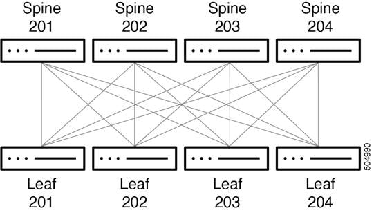
In this document, we are showing connectivity for 26 servers with two leaf switches per rack, as generally servers with several GPUs will take up at least 2 RU and the power requirements for these servers can be high. As mentioned earlier, this also leaves a few front panel ports in each leaf switch for extra connections for storage and other types of devices and external connectivity as needed.
The connectivity between the spine and leaf switches is accomplished as shown in the example in the table below, with more leaf switches added following this scheme:
|
|
Spine Int Eth1/1 and Eth1/11 |
Spine Int Eth1/2 and Eth1/12 |
Spine Int Eth1/3 and Eht1/13 |
Spine Int Eth1/4 and Eth1/14 |
| Spine 201 |
Leaf 201 Int Eth 1/29 and Eth1/30 |
Leaf 202 Int Eth 1/29 and Eth1/30 |
Leaf 203 Int Eth 1/29 and Eth1/30 |
Leaf 204 Int Eth 1/29 and Eth1/30 |
| Spine 202 |
Leaf 201 Int Eth 1/31 and Eth1/32 |
Leaf 202 Int Eth 1/31 and Eth1/32 |
Leaf 203 Int Eth 1/31 and Eth1/32 |
Leaf 204 Int Eth 1/31 and Eth1/32 |
| Spine 203 |
Leaf 201 Int Eth 1/33 and Eth1/34 |
Leaf 202 Int Eth 1/33 and Eth1/34 |
Leaf 203 Int Eth 1/33 and Eth1/34 |
Leaf 204 Int Eth 1/33 and Eth1/34 |
| Spine 204 |
Leaf 201 Int Eth 1/35 and Eth1/36 |
Leaf 202 Int Eth 1/35 and Eth1/36 |
Leaf 203 Int Eth 1/35 and Eth1/36 |
Leaf 204 Int Eth 1/35 and Eth1/36 |
With this cabling, each leaf switch has 8 x 400G connections to the spine layer, which provides 3.2Tb, or enough bandwidth, to connect up to 32 servers or other devices at 100G. As mentioned earlier, the Cisco Nexus 9332D-GX2B is a non-blocking switch and we can use all front panel ports for server connectivity. If we require more server connectivity, then we can add more leaf switches.
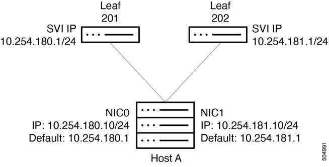
Each server is connected to a pair of leaf switches at 100G. Each connection is made to an "untagged" switchport. The connection are each in a different subnet. The leaf switches each has a /24 SVI, which is distributed using BGP. This allows the network interface cards (NICs) to be set up with an IP address and does not require any other configuration, which simplifies the server/NIC configuration. There are default routes in the servers pointing at each leaf switch SVI. The servers do their own load balancing as configured by their operating system for outgoing connectivity. DNS round robin can allow effective load balancing for incoming server connectivity. Server administrators do not have to work on port channel drivers and configurations for their NICs in addition to enabling ECN and PFC, which simplifies operations.
The spine and leaf switches use BGP for their control plane. Each leaf switch advertises its interface IP addresses, as well as the /24 SVI IP address used for server connectivity, to the spine switches. The uplinks use BFD in case of soft failures, as most other failures will be detected by link down. The leaf switches use AS 65011 and the spines use AS 65535.
Interface and BGP Configuration on Leaf 201:
<clip>
route-map fabric-rmap-redist-subnet permit 10
match tag 12345
<clip>
interface Vlan180
no shutdown
mtu 9216
ip address 10.254.180.1/24 tag 12345
<clip>
interface Ethernet1/1
description UCS 180 - 10.254.180.2
switchport
switchport access vlan 180
spanning-tree port type edge
spanning-tree bpduguard enable
mtu 9216sh run
no shutdown
<clip>
interface Ethernet1/29
description connected-to-spine-201-Ethernet1/1
mtu 9216
ip address 10.4.0.1/30
no shutdown
interface Ethernet1/30
description connected-to-spine-201-Ethernet1/11
mtu 9216
ip address 10.4.0.5/30
no shutdown
interface Ethernet1/31
description connected-to-spine-202-Ethernet1/2
mtu 9216
ip address 10.4.0.9/30
no shutdown
interface Ethernet1/32
description connected-to-spine-202-Ethernet1/12
mtu 9216
ip address 10.4.0.13/30
no shutdown
<clip>
interface loopback0
description Routing loopback interface
ip address 10.2.0.1/32 tag 12345
<clip>
router bgp 65011
router-id 10.2.0.1
address-family ipv4 unicast
redistribute direct route-map fabric-rmap-redist-subnet
maximum-paths 4
neighbor 10.4.0.2
bfd
remote-as 65535
description Spine-201-eth1/1
update-source Ethernet1/29
address-family ipv4 unicast
allowas-in 3
neighbor 10.4.0.6
bfd
remote-as 65535
description Spine-201-eth1/11
update-source Ethernet1/30
address-family ipv4 unicast
allowas-in 3
neighbor 10.4.0.10
bfd
remote-as 65535
description Spine-202-eth1/1
update-source Ethernet1/31
address-family ipv4 unicast
allowas-in 3
neighbor 10.4.0.14
bfd
remote-as 65535
description Spine-202-eth1/11
update-source Ethernet1/32
address-family ipv4 unicast
allowas-in 3
neighbor 10.4.0.18
bfd
remote-as 65535
description Spine-203-eth1/1
update-source Ethernet1/33
address-family ipv4 unicast
allowas-in 3
neighbor 10.4.0.22
bfd
remote-as 65535
description Spine-203-eth1/11
update-source Ethernet1/34
address-family ipv4 unicast
allowas-in 3
neighbor 10.4.0.26
bfd
remote-as 65535
description Spine-204-eth1/1
update-source Ethernet1/35
address-family ipv4 unicast
allowas-in 3
neighbor 10.4.0.30
bfd
remote-as 65535
description Spine-204-eth1/11
update-source Ethernet1/36
address-family ipv4 unicast
allowas-in 3
<clip>
BGP Configuration on Spine 201:
<clip>
route-map fabric-rmap-redist-subnet permit 10
match tag 12345
<clip>
interface Ethernet1/1
description connected-to-leaf-201-Ethernet1/29
mtu 9216
ip address 10.4.0.2/30
no shutdown
<clip>
interface loopback0
description Routing loopback interface
ip address 10.2.0.101/32 tag 12345
<clip>
router bgp 65535
router-id 10.2.0.101
address-family ipv4 unicast
redistribute direct route-map fabric-rmap-redist-subnet
maximum-paths 4
neighbor 10.4.0.1
bfd
remote-as 65011
description Leaf-201-eth1/29
update-source Ethernet1/1
address-family ipv4 unicast
disable-peer-as-check
neighbor 10.4.0.5
bfd
remote-as 65011
description Leaf-201-eth1/30
update-source Ethernet1/11
address-family ipv4 unicast
disable-peer-as-check
neighbor 10.4.0.33
bfd
remote-as 65011
description Leaf-202-eth1/29
update-source Ethernet1/2
address-family ipv4 unicast
disable-peer-as-check
neighbor 10.4.0.37
bfd
remote-as 65011
description Leaf-202-eth1/30
update-source Ethernet1/12
address-family ipv4 unicast
disable-peer-as-check
<clip>
neighbor 10.4.1.33
bfd
remote-as 65011
description Leaf-210-eth1/29
update-source Ethernet1/10
address-family ipv4 unicast
disable-peer-as-check
neighbor 10.4.1.37
bfd
remote-as 65011
description Leaf-210-eth1/30
update-source Ethernet1/20
address-family ipv4 unicast
disable-peer-as-check
<clip>
Building a Lossless Ethernet Fabric Using RoCEv2 As The Transport
As described in the blueprint, PFC and ECN complement each other to provide the most efficient congestion management. Together, they provide the highest throughput and lowest latency penalty during congestion to enable a lossless fabric. For most efficient congestion management, you must set the ECN and PFC thresholds correctly.
For Cisco Nexus 9000 switches, you configure QoS using the Cisco Modular Quality of Service Command-Line Interface (MQC). MQC provides three different class-map and policy-map object types: "type qos" for classification, "type queuing" for queuing and ECN configuration, and "type network-qos" for configuring PFC on the switch. Each of these types have their class-maps for traffic classification, policy-maps for actions to be applied to the classified traffic, and service-policies to attach the policy to an interface so it can perform the configured actions.
Document explains the QoS configuration CLI and shows how switches can be configured using the Cisco Nexus Dashboard Fabric Controller (NDFC).
The configuration in the example below is applied on all the switches in the network, and on all interfaces. The expectation is that hosts send RoCEv2 traffic marked with a DSCP value of 24 (CS3), and all switches use this priority value to put the traffic in the appropriate class. A policy-map refers back to the class-map and sets the appropriate traffic to "qos-group 3." This allows the traffic to be put in the right class for "type queuing" and "type network-qos." Furthermore, CNP traffic is classified and put in the strict priority queue. CNP traffic carries DSCP 48, and as such belong to "qos-group 7."
class-map type qos match-all class-q3
match dscp 24
class-map type qos match-all class-q7
match dscp 48
policy-map type qos QOS_classification_policy
class class-q3
set qos-group 3
class class-q7
set qos-group 7
class class-default
set qos-group 0
After the traffic is classified, the system is configured for queuing and scheduling. In this example, we have queue 3 (q3) assigned for RoCEv2 traffic. Queue 3 is assigned 60% of the bandwidth and q3 has WRED configured, with a minimum threshold set to 150 KB and a maximum threshold set to 3000 KB, and with a drop probability set to 7 percent. These are the recommended values for WRED in this case, as this network is optimized for high bandwidth ports of 100G and 400G. As CNP traffic is part of qos-group 7, it will use strict priority queue 7.
policy-map type queuing custom-8q-out-policy
class type queuing c-out-8q-q7
priority level 1
class type queuing c-out-8q-q6
bandwidth remaining percent 0
class type queuing c-out-8q-q5
bandwidth remaining percent 0
class type queuing c-out-8q-q4
bandwidth remaining percent 0
class type queuing c-out-8q-q3
bandwidth remaining percent 60
random-detect minimum-threshold 150 kbytes maximum-threshold 3000 kbytes drop-probability 7 weight 0 ecn
class type queuing c-out-8q-q2
bandwidth remaining percent 0
class type queuing c-out-8q-q1
bandwidth remaining percent 0
class type queuing c-out-8q-q-default
bandwidth remaining percent 40
To enable PFC and enhance the lossless capabilities of the network, you must use "network-qos." In this case, traffic in network-qos 3 is assigned to PFC traffic for class of service 3. While this nomenclature indicates that the system anticipates a VLAN tag with priority 3, this is not the case and the number refers to a queue that will become lossless. A MTU statement is present as well. While the MTU statement does not have influence on the traffic, it gives the system a way to calculate headroom for the non-drop queue. The PFC xOFF and xON thresholds are set to default values and have not been changed. The system does not display default values.
policy-map type network-qos custom-8q-nq-policy
<snip>
class type network-qos c-8q-nq3
mtu 9216
pause pfc-cos 3
<snip>
As this fabric is designed to provide lossless behavior, the configurations for "type queuing" and "type network-qos" need to be attached system wide. This guarantees that WRED will trigger ECN marking and that ports configured with PFC will receive and honor those frames, as well as generate pause frames when under congestion.
system qos
service-policy type network-qos custom-8q-nq-policy
service-policy type queuing output custom-8q-out-policy
The classification attachment must be done at the interface level. This allows any incoming traffic to be classified and assigned correctly. RoCEv2 traffic goes to qos-group 3. In addition to classification, the interface is configured with PFC "mode on". The interface is also configured with a PFC watch dog, using a default interval of 100 milliseconds. This configuration will be present on all interfaces on both the spine and leaf switches.
interface Ethernet1/1
service-policy type qos input QOS_classification_policy
priority-flow-control mode on
priority-flow-control watch-dog-interval on
Using NDFC to Build Your AI/ML Network
Irrespective of the network architecture choice, Layer 3 to the leaf switch, or using a VXLAN overlay, the Cisco Nexus Dashboard Fabric Controller (also known as the Fabric Controller service) provides best practice configurations and automation capabilities. Using NDFC, the entire network, including the QoS configuration for PFC and ECN, can be configured in a matter of minutes. The Fabric Controller service also provides automation to add new leaf or spine switches and make changes to access port configurations.
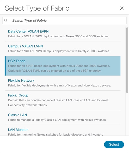
This example builds a network fabric from scratch using eBGP to build a Layer 3 network. This is done by using the BGP fabric template.
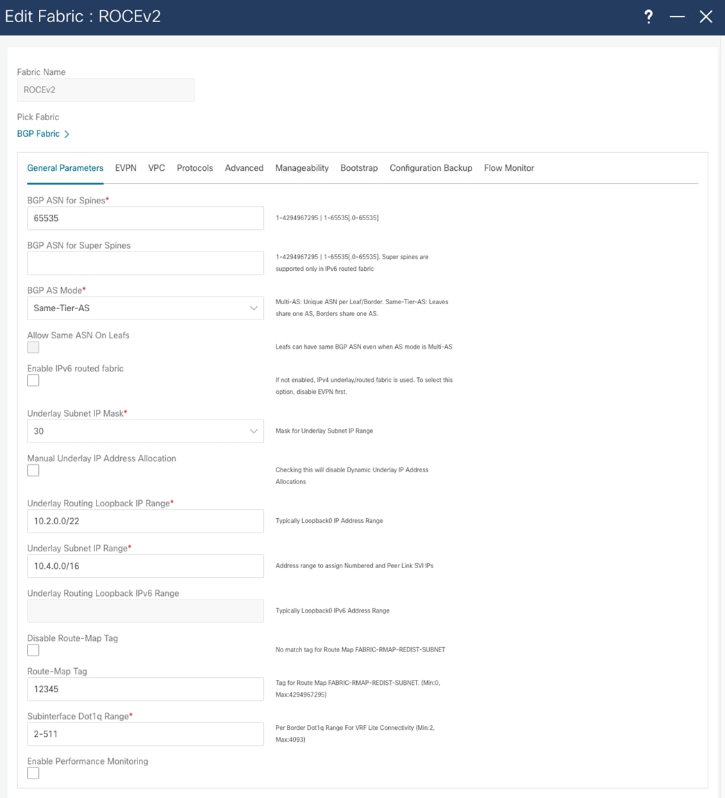
NDFC allows templates to be populated with the fabric-wide configuration. This configuration is divided into tabs in the template. In the General Parameters tab, the system allows the configuration of the spine ASN, the BGP redistribution in the leaf layer, the subnets used for inter fabric links, and a routing loopback subnet range.
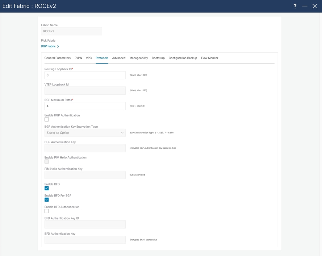
You enable BFD, which provides fast convergence times, at the time of fabric creation. You enable BFD for BGP in the Protocols tab.
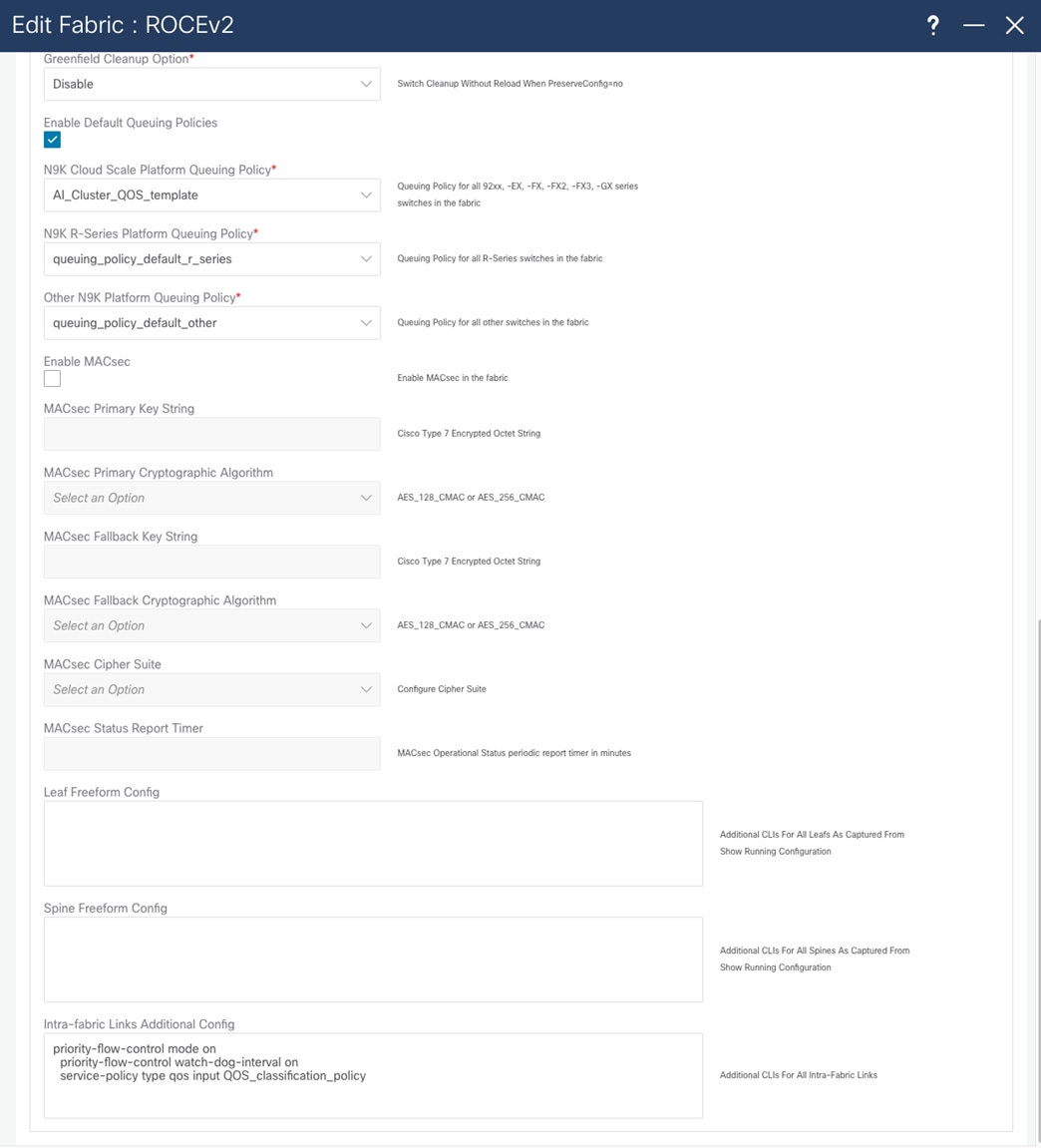
To enable QOS for the entire fabric, the Advanced tab enables you to choose the template that you will use. This allows all the switches to be configured correctly for RoCEv2 traffic to be treated in the same way across the entire fabric. You must deploy some configuration using the freeform method, where native CLI commands are sent to the switch for configuration. In the freeform configuration, the hierarchy and indentation must follow the way the running configuration would look in the switch.
After you create the fabric, add switches to it. Do this in the Fabric and Switch tab by providing a seed IP address and credentials. NDFC uses CDP neighborship from the seed switch to discover the network.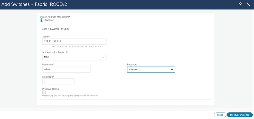
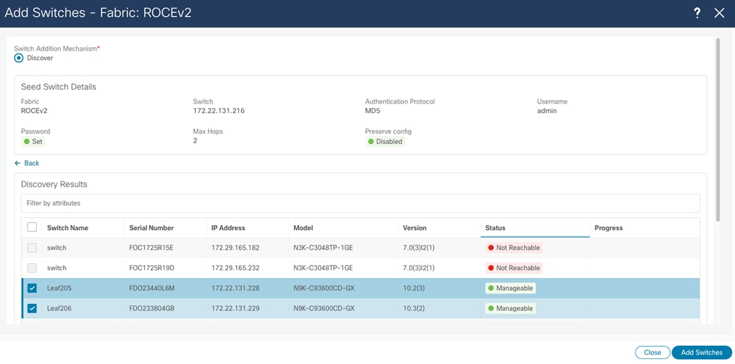
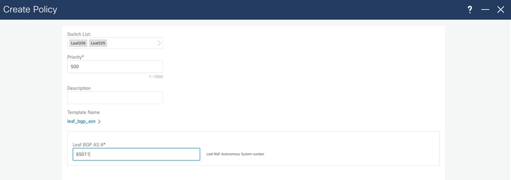
After you add the switches, NDFC deploys the fabric-wide configuration from the template. In this example, the BGP AS number is the same for all leaf switches, and you configure the BFG AS number through a policy template. All leaf switches are selected to receive this configuration.
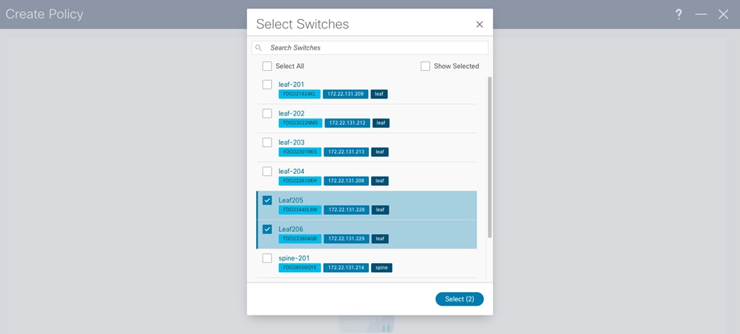
After you select all switches, you can configure the "leaf_bgp_asn" number.
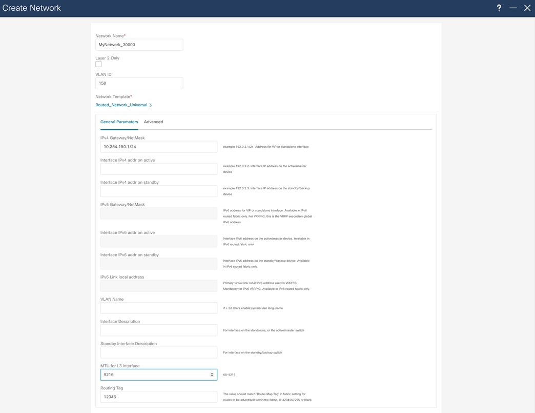
For host reachability and routing in the network, you must create an SVI interface and assign the correct VLAN to the access interfaces, which you do through the Fabric Networks menu. In the same menu, assign a Routing Tag that will advertise network through BGP.
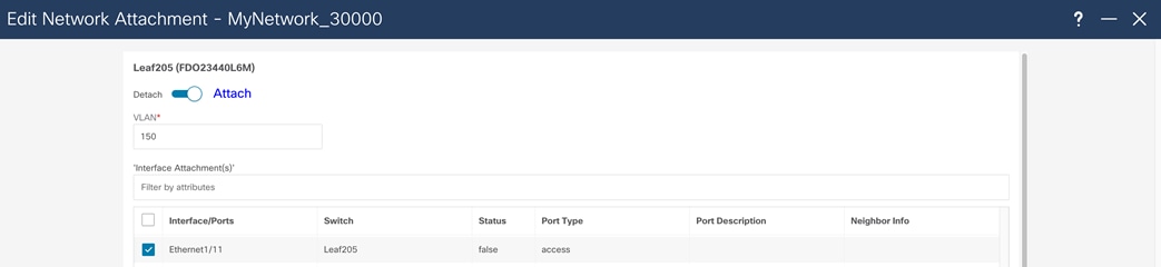
After you create the network, assigned the network to a switch and switch interface. To do that, double click on the network name and choose the Network Attachments tab. Next, choose the leaf switch where network will be attached, and in Actions menu choose Edit.
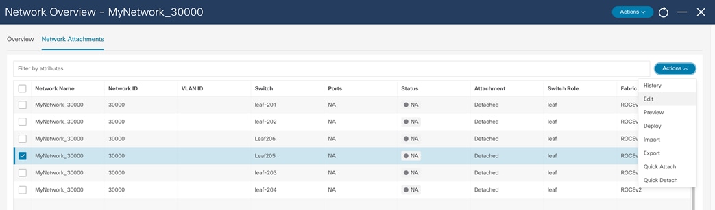
In the Edit Network Attachment menu, move the slider to Attach to assign the network to an interface and choose the interface where the network will be attached. After the network is deployed, the switch will be configured with the VLAN and appropriate SVI. The VLAN is then configured on the host interface.
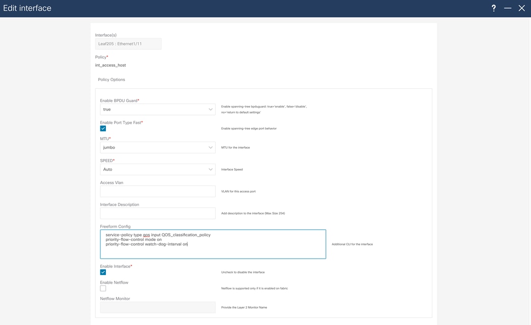
To complete the configuration, configure the host interface with a service-policy type QoS, as well PFC and PFC watchdog, using the freeform configuration.
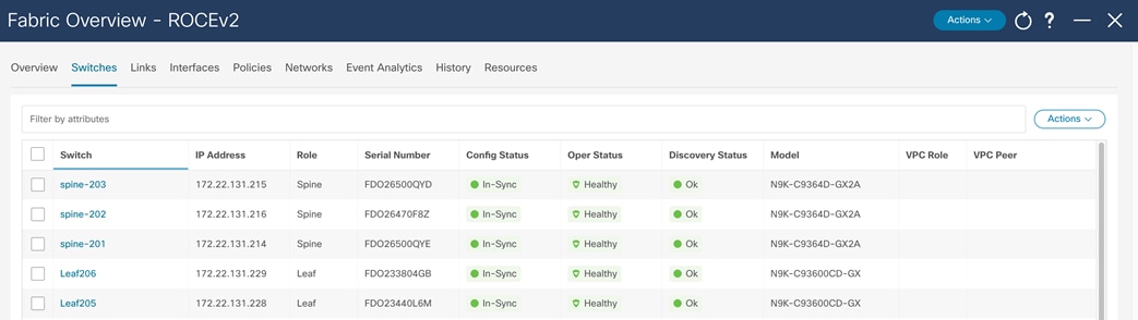
After you deploy this configuration successfully, all the switches show their configuration status, operational status, and discovery status as green on the Switch page of the fabric.
You can find detailed configuration information for NDFC in the following documents:
● Cisco Nexus 9000 Series NX-OS Quality of Service Configuration Guide, Release 10.3(x)
#show running-config
!Command: show running-config
!Running configuration last done at: Tue May 30 04:53:36 2023
!Time: Tue May 30 14:33:03 2023
version 10.2(3) Bios:version 05.44
hostname Leaf201
policy-map type network-qos custom-8q-nq-policy
class type network-qos c-8q-nq7
mtu 1500
class type network-qos c-8q-nq3
pause pfc-cos 3
mtu 9216
class type network-qos c-8q-nq-default
mtu 1500
vdc Leaf201 id 1
limit-resource vlan minimum 16 maximum 4094
limit-resource vrf minimum 2 maximum 4096
limit-resource port-channel minimum 0 maximum 511
limit-resource m4route-mem minimum 58 maximum 58
limit-resource m6route-mem minimum 8 maximum 8
feature nxapi
cfs eth distribute
feature bgp
feature interface-vlan
feature lldp
feature bfd
username admin password 5 $5$BIBMDM$jqAV76tLYoaU5qMMZzh0hR33mKRO2VEwEUN4Awy/pyB role network-admin
ip domain-lookup
class-map type qos match-all class-q3
match dscp 24
class-map type qos match-all class-q7
match dscp 48
policy-map type qos QOS_classification_policy
class class-q3
set qos-group 3
class class-q7
set qos-group 7
class class-default
set qos-group 0
policy-map type queuing custom-8q-out-policy
class type queuing c-out-8q-q7
priority level 1
class type queuing c-out-8q-q6
bandwidth remaining percent 0
class type queuing c-out-8q-q5
bandwidth remaining percent 0
class type queuing c-out-8q-q4
bandwidth remaining percent 0
class type queuing c-out-8q-q3
bandwidth remaining percent 60
random-detect minimum-threshold 150 kbytes maximum-threshold 3000 kbytes drop-probability 7 weight 0 ecn
class type queuing c-out-8q-q2
bandwidth remaining percent 0
class type queuing c-out-8q-q1
bandwidth remaining percent 0
class type queuing c-out-8q-q-default
bandwidth remaining percent 40
system qos
service-policy type network-qos custom-8q-nq-policy
service-policy type queuing output custom-8q-out-policy
copp profile strict
snmp-server user admin network-admin auth md5 364A9ED2C28A591C2EE9BBB3C8A75F8E254D priv aes-128 0166B1E5A4FB7C0F0CB2F1BAD8AB4DCE2540 localizedV2key
snmp-server host 172.22.131.220 traps version 2c public udp-port 2162
rmon event 1 log trap public description FATAL(1) owner PMON@FATAL
rmon event 2 log trap public description CRITICAL(2) owner PMON@CRITICAL
rmon event 3 log trap public description ERROR(3) owner PMON@ERROR
rmon event 4 log trap public description WARNING(4) owner PMON@WARNING
rmon event 5 log trap public description INFORMATION(5) owner PMON@INFO
ipv6 switch-packets lla
vlan 1,180
route-map fabric-rmap-redist-subnet permit 10
match tag 12345
vrf context management
ip route 0.0.0.0/0 x.x.x.x
nxapi http port 80
interface Vlan180
no shutdown
mtu 9216
no ip redirects
ip address 10.254.180.1/24 tag 12345
no ipv6 redirects
interface Ethernet1/1
description UCS 150 100G0
switchport
switchport access vlan 180
priority-flow-control mode on
priority-flow-control watch-dog-interval on
spanning-tree port type edge
spanning-tree bpduguard enable
mtu 9216
service-policy type qos input QOS_classification_policy
no shutdown
interface Ethernet1/2
description UCS 151 100G0
switchport
switchport access vlan 180
priority-flow-control mode on
priority-flow-control watch-dog-interval on
spanning-tree port type edge
spanning-tree bpduguard enable
mtu 9216
service-policy type qos input QOS_classification_policy
no shutdown
interface Ethernet1/3
description UCS 152 100G0
switchport
switchport access vlan 180
priority-flow-control mode on
priority-flow-control watch-dog-interval on
spanning-tree port type edge
spanning-tree bpduguard enable
mtu 9216
service-policy type qos input QOS_classification_policy
no shutdown
<clip>
interface Ethernet1/29
description connected-to-spine-201-Ethernet1/1
priority-flow-control mode on
priority-flow-control watch-dog-interval on
mtu 9216
service-policy type qos input QOS_classification_policy
no ip redirects
ip address 10.4.0.1/30
no ipv6 redirects
no shutdown
interface Ethernet1/30
description connected-to-spine-201-Ethernet1/11
priority-flow-control mode on
priority-flow-control watch-dog-interval on
mtu 9216
service-policy type qos input QOS_classification_policy
no ip redirects
ip address 10.4.0.5/30
no ipv6 redirects
no shutdown
interface Ethernet1/31
description connected-to-spine-202-Ethernet1/2
priority-flow-control mode on
priority-flow-control watch-dog-interval on
mtu 9216
service-policy type qos input QOS_classification_policy
no ip redirects
ip address 10.4.0.9/30
no ipv6 redirects
no shutdown
interface Ethernet1/32
description connected-to-spine-202-Ethernet1/12
priority-flow-control mode on
priority-flow-control watch-dog-interval on
mtu 9216
service-policy type qos input QOS_classification_policy
no ip redirects
ip address 10.4.0.13/30
no ipv6 redirects
no shutdown
interface Ethernet1/33
description connected-to-spine-203-Ethernet1/2
priority-flow-control mode on
priority-flow-control watch-dog-interval on
mtu 9216
service-policy type qos input QOS_classification_policy
no ip redirects
ip address 10.4.0.17/30
no ipv6 redirects
no shutdown
interface Ethernet1/34
description connected-to-spine-203-Ethernet1/12
priority-flow-control mode on
priority-flow-control watch-dog-interval on
mtu 9216
service-policy type qos input QOS_classification_policy
no ip redirects
ip address 10.4.0.21/30
no ipv6 redirects
no shutdown
interface Ethernet1/35
description connected-to-spine-204-Ethernet1/2
priority-flow-control mode on
priority-flow-control watch-dog-interval on
mtu 9216
service-policy type qos input QOS_classification_policy
no ip redirects
ip address 10.4.0.25/30
no ipv6 redirects
no shutdown
interface Ethernet1/36
description connected-to-spine-204-Ethernet1/12
priority-flow-control mode on
priority-flow-control watch-dog-interval on
mtu 9216
service-policy type qos input QOS_classification_policy
no ip redirects
ip address 10.4.0.29/30
no ipv6 redirects
no shutdown
interface mgmt0
vrf member management
ip address x.x.x.x/24
interface loopback0
description Routing loopback interface
ip address 10.2.0.1/32 tag 12345
line console
line vty
boot nxos bootflash:/nxos64-cs.10.2.3.F.bin
router bgp 65011
router-id 10.2.0.1
address-family ipv4 unicast
redistribute direct route-map fabric-rmap-redist-subnet
maximum-paths 4
neighbor 10.4.0.2
bfd
remote-as 65535
description Spine-201-eth1/1
update-source Ethernet1/29
address-family ipv4 unicast
allowas-in 3
neighbor 10.4.0.6
bfd
remote-as 65535
description Spine-201-eth1/11
update-source Ethernet1/30
address-family ipv4 unicast
allowas-in 3
neighbor 10.4.0.10
bfd
remote-as 65535
description Spine-202-eth1/1
update-source Ethernet1/31
address-family ipv4 unicast
allowas-in 3
neighbor 10.4.0.14
bfd
remote-as 65535
description Spine-202-eth1/11
update-source Ethernet1/32
address-family ipv4 unicast
allowas-in 3
neighbor 10.4.0.18
bfd
remote-as 65535
description Spine-203-eth1/1
update-source Ethernet1/33
address-family ipv4 unicast
allowas-in 3
neighbor 10.4.0.22
bfd
remote-as 65535
description Spine-203-eth1/11
update-source Ethernet1/34
address-family ipv4 unicast
allowas-in 3
neighbor 10.4.0.26
bfd
remote-as 65535
description Spine-204-eth1/1
update-source Ethernet1/35
address-family ipv4 unicast
allowas-in 3
neighbor 10.4.0.30
bfd
remote-as 65535
description Spine-204-eth1/11
update-source Ethernet1/36
address-family ipv4 unicast
allowas-in 3
Leaf201#
# show running-config
!Command: show running-config
!Running configuration last done at: Tue May 30 04:55:49 2023
!Time: Tue May 30 14:37:00 2023
version 10.3(2) Bios:version 01.13
hostname spine-201
policy-map type network-qos custom-8q-nq-policy
class type network-qos c-8q-nq7
class type network-qos c-8q-nq3
mtu 9216
pause pfc-cos 3
class type network-qos c-8q-nq-default
vdc spine-201 id 1
limit-resource vlan minimum 16 maximum 4094
limit-resource vrf minimum 2 maximum 4097
limit-resource port-channel minimum 0 maximum 511
limit-resource m4route-mem minimum 58 maximum 58
limit-resource m6route-mem minimum 8 maximum 8
feature nxapi
feature bgp
feature lldp
feature bfd
username admin password 5 $5$BNKINK$BCDb0mtoGtAE8WUcKLNoLBRtB9iU8Q3ydYydmKq5ir8 role network-admin
ip domain-lookup
class-map type qos match-all class-q3
match dscp 24
class-map type qos match-all class-q7
match dscp 48
policy-map type qos QOS_classification_policy
class class-q3
set qos-group 3
class class-q7
set qos-group 7
class class-default
set qos-group 0
policy-map type queuing custom-8q-out-policy
class type queuing c-out-8q-q7
priority level 1
class type queuing c-out-8q-q6
bandwidth remaining percent 0
class type queuing c-out-8q-q5
bandwidth remaining percent 0
class type queuing c-out-8q-q4
bandwidth remaining percent 0
class type queuing c-out-8q-q3
bandwidth remaining percent 60
random-detect minimum-threshold 150 kbytes maximum-threshold 3000 kbytes drop-probability 7 weight 0 ecn
class type queuing c-out-8q-q2
bandwidth remaining percent 0
class type queuing c-out-8q-q1
bandwidth remaining percent 0
class type queuing c-out-8q-q-default
bandwidth remaining percent 40
system qos
service-policy type network-qos custom-8q-nq-policy
service-policy type queuing output custom-8q-out-policy
copp profile strict
snmp-server user admin network-admin auth md5 175DE4ED111F28DB8D973F2499DB7E993F3C priv aes-128 167AE6C0626C04FBBEB1772889D75E83286D localizedV2key
snmp-server host 172.22.131.220 traps version 2c public udp-port 2162
rmon event 1 log trap public description FATAL(1) owner PMON@FATAL
rmon event 2 log trap public description CRITICAL(2) owner PMON@CRITICAL
rmon event 3 log trap public description ERROR(3) owner PMON@ERROR
rmon event 4 log trap public description WARNING(4) owner PMON@WARNING
rmon event 5 log trap public description INFORMATION(5) owner PMON@INFO
ipv6 switch-packets lla
vlan 1
route-map fabric-rmap-redist-subnet permit 10
match tag 12345
vrf context management
ip route 0.0.0.0/0 x.x.x.x
nxapi http port 80
interface Ethernet1/1
description connected-to-leaf-201-Ethernet1/29
priority-flow-control mode on
priority-flow-control watch-dog-interval on
mtu 9216
service-policy type qos input QOS_classification_policy
no ip redirects
ip address 10.4.0.2/30
no ipv6 redirects
no shutdown
interface Ethernet1/2
description connected-to-leaf-202-Ethernet1/29
priority-flow-control mode on
priority-flow-control watch-dog-interval on
mtu 9216
service-policy type qos input QOS_classification_policy
no ip redirects
ip address 10.4.0.34/30
no ipv6 redirects
no shutdown
<clip>
interface Ethernet1/10
description connected-to-leaf-210-Ethernet1/29
priority-flow-control mode on
priority-flow-control watch-dog-interval on
mtu 9216
service-policy type qos input QOS_classification_policy
no ip redirects
ip address 10.4.1.34/30
no ipv6 redirects
no shutdown
interface Ethernet1/11
description connected-to-leaf-201-Ethernet1/30
priority-flow-control mode on
priority-flow-control watch-dog-interval on
mtu 9216
service-policy type qos input QOS_classification_policy
no ip redirects
ip address 10.4.0.6/30
no ipv6 redirects
no shutdown
interface Ethernet1/12
description connected-to-leaf-202-Ethernet1/30
priority-flow-control mode on
priority-flow-control watch-dog-interval on
mtu 9216
service-policy type qos input QOS_classification_policy
no ip redirects
ip address 10.4.0.38/30
no ipv6 redirects
no shutdown
<clip>
interface mgmt0
vrf member management
ip address x.x.x.x/24
interface loopback0
description Routing loopback interface
ip address 10.2.0.101/32 tag 12345
line console
line vty
boot nxos bootflash:/nxos64-cs.10.3.2.F.bin
router bgp 65535
router-id 10.2.0.101
address-family ipv4 unicast
redistribute direct route-map fabric-rmap-redist-subnet
maximum-paths 4
neighbor 10.4.0.1
bfd
remote-as 65011
description Leaf-201-eth1/29
update-source Ethernet1/1
address-family ipv4 unicast
disable-peer-as-check
neighbor 10.4.0.5
bfd
remote-as 65011
description Leaf-201-eth1/30
update-source Ethernet1/11
address-family ipv4 unicast
disable-peer-as-check
neighbor 10.4.0.33
bfd
remote-as 65011
description Leaf-202-eth1/29
update-source Ethernet1/2
address-family ipv4 unicast
disable-peer-as-check
neighbor 10.4.0.37
bfd
remote-as 65011
description Leaf-202-eth1/30
update-source Ethernet1/12
address-family ipv4 unicast
disable-peer-as-check
<clip>
neighbor 10.4.1.33
bfd
remote-as 65011
description Leaf-210-eth1/29
update-source Ethernet1/10
address-family ipv4 unicast
disable-peer-as-check
neighbor 10.4.1.37
bfd
remote-as 65011
description Leaf-210-eth1/30
update-source Ethernet1/20
address-family ipv4 unicast
disable-peer-as-check
Spine201#
Versions of Software Used in This Validated Design
● NX-OS: 10.3.2.F
● NDFC: 12.1.2
| Americas Headquarters Cisco Systems, Inc. San Jose, CA |
Asia Pacific Headquarters Cisco Systems (USA) Pte. Ltd. Singapore |
Europe Headquarters Cisco Systems International BV Amsterdam The Netherlands |
Cisco has more than 200 offices worldwide. Address, phone numbers, and fax numbers are listed on the Cisco Website at https://www.cisco.com/go/offices.
Cisco and the Cisco logo are trademarks or registered trademarks of Cisco and/or its affiliates in the U.S. and other countries. To view a list of Cisco trademarks, go to this URL: https://www.cisco.com/go/trademarks. Third-party trademarks mentioned are the property of their respective owners. The use of the word partner does not imply a partnership relationship between Cisco and any other company. (1110R)