Microsoft Azure Stack HCI Connectivity to Cisco Nexus 9000 Series Switches in Cisco NX-OS and Cisco® Application Centric Infrastructure (Cisco ACI™) Mode
Available Languages
Bias-Free Language
The documentation set for this product strives to use bias-free language. For the purposes of this documentation set, bias-free is defined as language that does not imply discrimination based on age, disability, gender, racial identity, ethnic identity, sexual orientation, socioeconomic status, and intersectionality. Exceptions may be present in the documentation due to language that is hardcoded in the user interfaces of the product software, language used based on RFP documentation, or language that is used by a referenced third-party product. Learn more about how Cisco is using Inclusive Language.
- US/Canada 800-553-2447
- Worldwide Support Phone Numbers
- All Tools
 Feedback
 Feedback
Contents
Cisco Application Centric Infrastructure
Cisco Nexus 9000 NX-OS based Fabric
Cisco Nexus 9000 Series Switch based Fabric and Benefit
Cisco ACI Design for Azure Stack HCI Connectivity
Cisco ACI for Azure Stack HCI Connectivity
Azure Stack HCI ACI Tenant Model Overview
Cisco NX-OS based Fabric Design for Azure Stack HCI Connectivity
Cisco NX-OS based Fabric for Azure Stack HCI Connectivity
Cisco ACI Configuration for Azure Stack HCI
Configuring Leaf Interfaces Connected to Azure Stack HCI Servers
Cisco NX-OS based Fabric configuration for Azure Stack HCI
Configure Networks for Azure Stack HCI
Build External Connectivity for Azure Stack HCI servers
Note: This document contains material and data with multiple dependencies. The information may be updated as and when necessary and is subject to change without notice.
Privileged/Confidential information is contained in this document and may be subject to legal privilege. Access to this material by anyone other than those intended is unauthorized. If you are not the intended recipient (or responsible for delivery of the information to such person), you may not use, copy, distribute, or deliver to anyone this information (or any part of its contents) or take any action in reliance on it. In such case, you should destroy this information and notify Cisco immediately. If you have received this material in error, please notify us immediately and delete the material from any computer. If you or your employer does not consent to this message, please notify us immediately. Our company cannot accept responsibility for any loss or damage arising from the use of this material.
This document describes the network design considerations for Microsoft Azure Stack Hyperconverged Infrastructure (HCI) in a Cisco Nexus 9000 Series Switches-based network with Cisco NX-OS and Cisco® Application Centric Infrastructure (Cisco ACI™).
This document assumes that you have a basic knowledge of Cisco ACI and Cisco NX-OS VXLAN technology.
For more information on Cisco ACI, refer to the white papers on Cisco.com: https://www.cisco.com/c/en/us/solutions/data-center-virtualization/application-centric-infrastructure/white-paper-listing.html
For more information on Cisco NX-OS based VXLAN fabrics, refer to the white papers on Cisco.com: https://www.cisco.com/c/en/us/products/switches/nexus-9000-series-switches/white-paper-listing.html
● Cisco ACI related terminologies
BD: bridge domain
EPG: endpoint group
L3Out: Layer 3 Out or external routed network
L3Out EPG: subnet-based EPG in L3Out
VRF: Virtual Routing and Forwarding
Border leaf: ACI leaf where L3Out is deployed
● Cisco NX-OS related terminologies
NDFC: Nexus Dashboard Fabric Controller
VXLAN: Virtual Extensible LAN
VNI: Virtual Network Identifier (one to one co-relation between VLAN to VNI)
DAG: Distributed Anycast Gateway
Leaf: Performs VXLAN encapsulation and decapsulation function also referred as Virtual Tunnel End-Point (VTEP). End-hosts are connected to Leafs in the VXLAN fabric
Spine: Provides Underlay Layer-3 connectivity between the leafs in the VXLAN fabric
Border Leaf: Performs similar function to a Leaf. In addition, Border leafs connect the VXLAN fabric to external networks and are placed at the edge of the VXLAN fabric
External Connectivity: Provide L3 connectivity outside of the VXLAN fabric
● Microsoft Azure Stack HCI related terminologies
RDMA: Remote Direct Memory Access
RoCE: RDMA over Converged Ethernet
SET: Switch Embedded Teaming
SMB: Server Message Block
Storage Spaces Direct: A feature of the Microsoft Azure Stack HCI and Windows Server that enables you to cluster servers with an internal storage into a software-defined storage solution. Storage Spaces Direct uses SMB3, including SMB Direct and SMB Multichannel over Ethernet to communicate between servers
SMB Direct: The Windows Server includes a feature called SMB Direct, which supports the use of network adapters that have RDMA capability. Network adapters with RDMA capability can function at full speed with lower latency without compromising CPU utilization. SMB Direct requires network adapters with RDMA capability on the servers and RDMA over Converged Ethernet (RoCEv2) on the network
Beginning with Cisco ACI Release 6.0(3e) and NX-OS 10.3(2)F, Nexus 9000 Series Switches support the Microsoft Azure Stack HCI requirements. This document details the Microsoft Azure Stack HCI network design with Cisco Nexus 9000 Series Switches in either Cisco ACI or Cisco NX-OS mode.
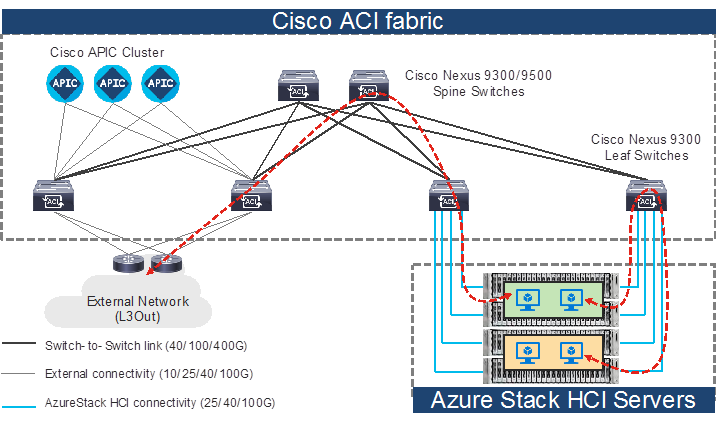
Topology example with Nexus 9000 Series Switches in Cisco ACI mode
Note: Cisco Application Policy Infrastructure Controller (APIC) can be connected to leaf switches directly or connected through the Layer 3 network via spine switches.
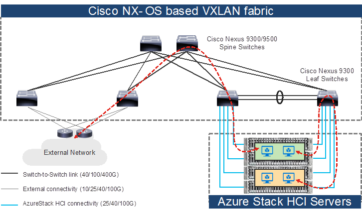
Topology example with Nexus 9000 Series Switches in Cisco NX-OS mode
While installing the Microsoft Azure Stack HCI, you must ensure that there are direct connections from the Microsoft Azure Stack HCI servers to the Cisco Nexus 9000 Top-of-Rack (ToR) switches; and ensure accessibility to the data center, among other required tasks.
This document is intended to provide information, education, and guidance for individuals or organizations who are interested in connecting their Microsoft Azure Stack HCI servers to an existing Cisco Nexus 9000 Series Switch-based network in their data centers. The document provides fundamental information and recommended configurations based on internal testing of the solution. This document does not cover the installation and configuration process of Cisco ACI or NX-OS based infrastructure and details on how to set up the Microsoft Azure Stack HCI.
This document uses Cisco UCS C240 M6/M7 servers as the Microsoft Azure Stack HCI servers. For Cisco UCS configuration and design considerations, refer to the Cisco Validated Design (CVD) on cisco.com: https://www.cisco.com/c/en/us/td/docs/unified_computing/ucs/UCS_CVDs/ucs_mas_hci_m7.html.
The Microsoft Azure Stack HCI internal networks are not managed using a Cisco controller such as Cisco APIC and NDFC in this solution. The Azure Stack HCI system is connected to the Nexus 9000 Series Switch-based network, which acts as the gateway to allow the Azure Stack HCI VMs to connect with other VMs, the external network, and other internal network services in the datacenter.
This section introduces the technologies that are used in the solution, which are described in this document.
About Cisco ACI
Cisco ACI is an evolutionary leap from SDN’s initial vision of operational efficiency through network agility and programmability. Cisco ACI has industry leading innovations in management automation, programmatic policies, and dynamic workload provisioning. The ACI fabric accomplishes this with a combination of hardware, policy-based control systems, and closely coupled software to provide advantages that is not possible in other architectures.
Cisco ACI takes a policy-based systems approach to operationalizing the data center network. The policy is centered around the needs (reachability, access to services, and security policies) of the applications. Cisco ACI delivers a resilient fabric to satisfy today's dynamic applications.
The Cisco ACI fabric is a leaf-and-spine architecture where each leaf connects to every spine by using high-speed 40/100/400-Gbps Ethernet links, with no direct connection between the spine switches or leaf switches. The ACI fabric is a routed fabric with a VXLAN overlay network, where every leaf is VXLAN Tunnel Endpoint (VTEP). Cisco ACI provides both Layer 2 (L2) and Layer 3 (L3) forwarding across this routed fabric infrastructure.
The following are the ACI fabric components:
Cisco APIC: Cisco Application Policy Infrastructure Controller (APIC) is the unifying point of automation and management for the Cisco ACI fabric. Cisco APIC is a centralized, clustered controller that provides centralized access to all fabric information, optimizes the application lifecycle for scale and performance, and supports flexible application provisioning across physical and virtual resources. Cisco APIC exposes northbound APIs through XML and JSON and provides both a command-line interface (CLI) and a GUI, which utilize the APIs to manage the fabric.
Leaf Switches: The ACI leaf provides physical connectivity for servers, storage devices, and other access layer components as well as enforces the ACI policies. Leaf switches also provide connectivity to an existing enterprise or a service provider infrastructure. The leaf switches provide options starting at 1G up through 400G Ethernet ports for connectivity.
Spine Switches: In ACI, spine switches provide the mapping database function and connectivity between leaf switches. A spine switch can be the modular Cisco Nexus 9500 series equipped with ACI ready line cards or a fixed form-factor switch, such as the Cisco Nexus 9332D-GX2B. Spine switches provide high-density 40/100/400 Gigabit Ethernet connectivity to the leaf switches.
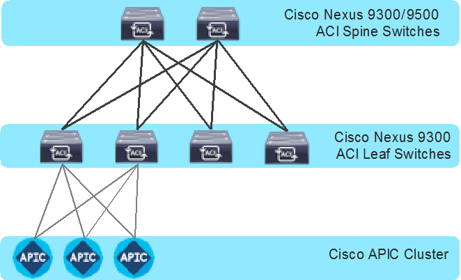
Cisco ACI Fabric Components
Cisco Nexus 9000 NX-OS based Fabric
Cisco NX-OS based fabric is another option for building a data center by using the Nexus 9000 series switches. These switches act as independent devices and have their own control-plane and data-plane. Nexus 9000 series switches running NX-OS offer various data Center fabric options, such as VXLAN, L3 Routed or traditional (2-tier or 3-tier) LAN.
This document only focuses on connecting the Azure Stack HCI to the VXLAN fabric. However, NX-OS based L3 Routed or traditional LAN fabrics can also be used.
The following are the Cisco NX-OS based VXLAN fabric components:
NDFC: Cisco Nexus Dashboard Fabric Controller (NDFC) is an Orchestration and Automation tool to build and manage data center fabrics. Cisco NDFC can be used either in LAN or SAN mode. In LAN mode, NDFC supports various fabric templates to create VXLAN, VXLAN Multisite, L3 Routed Fabric, and traditional LAN and IP Fabrics for media. Cisco NDFC offers the following day 0 to day 2 operations:
● Day 0: Bootstrap (POAP) support for the devices and pre-provisioning of the fabrics.
● Day 1: Automation of new Greenfield fabrics as well as support for Brownfield fabrics, deployment for Networks & VRFs, and L4-L7 service insertion.
● Day 2: Image Management, RMA workflow, Change Control & Rollback, monitoring of devices health and interfaces.
Cisco NDFC is optional. A VXLAN fabric can also be managed through the traditional CLI. But using Cisco NDFC has its own advantages. As stated above Cisco NDFC provides full automation support for all types of data center fabrics by eliminating the chance for human errors.
Nexus 9000 Series Switches: Nexus 9000 switches are data center switches for a hybrid cloud networking foundation. The Cisco Nexus 9000 Series offers modular and fixed form-factors and can deliver 1Gig to 800 Gig of line-rate forwarding.
VXLAN EVPN Fabric: VXLAN EVPN is the de-facto standard of building large scale data center fabrics, which provides seamless mobility of the hosts, tenant isolation, large name space for L2 segments, and traffic entropy across all the ECMP paths.
Spine Switches: In the VXLAN fabric, spine switches provide connectivity between all the leaf switches by using high speed links. Spines are not used to connect end-hosts.
Leaf Switches: Leaf switches function as VTEP and are responsible for the encapsulation and decapsulation of the VXLAN header. End-hosts are terminated on the leaf switches.
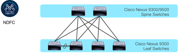
Cisco NX-OS based Fabric Components
Prior to implementing the solution, it is important to understand the logical architecture of the Microsoft Azure Stack HCI and how it maps to the underlying physical architecture. This section describes the logical and physical connectivity of the Microsoft Azure Stack HCI, and the Nexus 9000 Series Switch based network with either the Cisco ACI or Cisco NX-OS mode.
Each Cisco UCS C240 M6/M7 server is connected to a pair of Cisco Nexus 9000 Top-of-Rack (ToR) switches using dual 100Gb connections. In this example, the Cisco Nexus 9000 Series Switch based data center network carries all the Azure Stack HCI network traffic (management for host operating system, cluster communication, compute, and storage traffic). You can also use different networks.
Physical server management, such as Cisco Integrated Management Controller (CIMC) on Cisco UCS C series is facilitated through an Out-of-band (OOB) management network that connects the server’s dedicated management port to an OOB management switch with 1GbE links.
The following diagram illustrates a high-level physical architecture design:
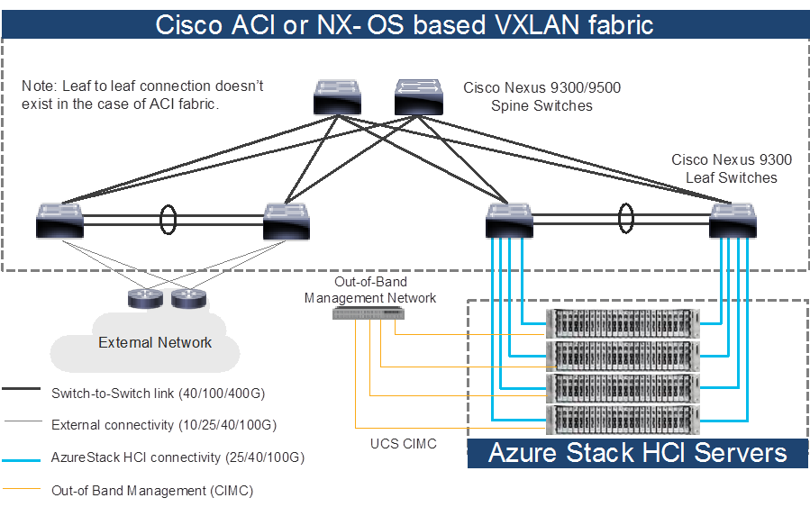
Physical Architecture (Cisco ACI or NX-OS mode)
In the case of Cisco NX-OS mode, the use of spine-leaf topology is not mandatory though it’s a common design option whereas the Cisco ACI mode requires spine-leaf topology. Although downstream vPC is not used to connect the Microsoft Azure Stack HCI server to a pair of ToR switches, the use of vPC peer-link is recommended.
Note: As the only difference between ACI based fabric and NX-OS based fabric is a vPC peer-link, this document uses the topology illustration with a vPC peer-link. This vPC peer-link doesn’t exist in the ACI fabric.
Physical connectivity considerations include the following:
● Microsoft recommends a 10+ Gigabit Ethernet network with remote-direct memory access (RDMA).
For UCS C240 M6/M7 based Azure Stack HCI, the NVIDIA ConnectX-6X dual Port 100 Gigabit Ethernet NIC card is required. (Cisco VIC is currently not an option).
Microsoft requires that all server nodes be configured the same.
Up to 16 Azure Stack HCI servers per cluster.
● The Microsoft Azure Stack HCI server interfaces are connected to a pair of ToR switches with individual links, not Virtual Port Channel (vPC).
● The pair of ToR switches don’t have to be dedicated to Azure Stack HCI connectivity.
● The ToR switches are configured for a MTU size of 9216. The MTU size for the packets sent on the network are controlled by the endpoints.
The network infrastructure for Azure Stack HCI consists of several logical networks:
● Tenant (Compute) Network: The tenant network is a VLAN trunk that carries one or more VLANs that provide access to the tenant virtual machines. Each VLAN is provisioned in the ToR switch and the SET switch that is running on the physical server. Each tenant VLAN is expected have an IP subnet assigned to it.
● Management Network (native VLAN is preferred but tagged VLAN is also supported): The management network is a VLAN that carries network traffic to the parent partition. This management network is used to access the host operating system. The connectivity to the management network is provided by the management (Mgmt) vNIC in the parent partition. Fault tolerance for the management vNIC is provided by the SET switch. A bandwidth limit can be assigned to the management, as necessary.
● Storage Network: The storage network carries RoCEv2 network traffic that is used for Storage Spaces Direct, storage replication, and Live Migration network traffic. The storage network has a Storage A and a Storage B segment, each with its own IP subnet. This design keeps the east-west RDMA isolated to the ToR switches.
In this document, the storage network is also used as a preferred path for cluster communication. (If both Storage A and Storage B segments are not available, the management network is used for cluster communication).
The following diagrams illustrate the tenant and management network (Figure 6) and storage network (Figure 7). For tenant and management network, ToRs provide the gateway functionality.
The default gateway of servers running on Azures Stack HCI are the anycast gateways provided by the ToRs.
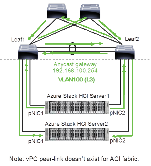
Azure Stack HCI Logical Architecture (tenant and management network)
Unlike tenant and management networks, storage networks require separate VLANs to connect a pair of ToRs. For example, VLAN 10 is used to connect Leaf1 (Storage A segment) and VLAN 20 is used to connect Leaf2 (Storage B segment).
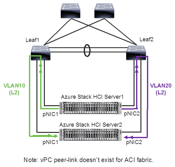
Azure Stack HCI Logical Architecture (storage network)
Storage network design considerations include the following:
● The storage network is used for Layer 2 communication only, where gateways on the ToR switches are not required.
● The storage network carries RoCEv2 traffic that is used for Storage Spaces Direct, storage replication, and Live Migration network traffic. Also used as a preferred path for cluster communication in this document.
● RoCE requires Data Center Bridging (DCB) to make the network lossless (DCB is optional for iWARP). If DCB is used, PFC and ETS configuration needs to be implemented in the network.
● As the storage network is also used as a preferred path for cluster communication in this document a different QoS configuration is required for storage traffic and cluster communication traffic. For example, Cos 4 is for storage traffic and Cos 7 is for cluster communication traffic.
The following table shows the QoS recommendations provided by Microsoft.
Table 1. Azure Stack HCI network QoS recommendation
| Cluster Communication Traffic |
Storage traffic |
Default (Tenant and Management Networks) |
|
| Purpose |
Bandwidth reservation for cluster heatbeats |
Bandwidth reservation for lossless RDMA communication used for Storage Spaces Direct |
For all other traffic such as tenant networks.
|
| Flow Control (PFC enabled) |
No |
Yes |
No |
| Traffic Class |
7 |
3 or 4 |
0 (default) |
| Bandwidth reservation |
1% for 25GbE or higher RDMA networks 2% for 10GbE or lower RDMA networks |
50% |
Default (no host configuration required) |
Note: Although the storage network is also used as a preferred path for cluster communication in this document, cluster communication could take any available network called as a preferred path. This path is chosen based on the metric role that is defined in the cluster network configured through Microsoft Network ATC. (Microsoft Network ATC provides an intent-based approach (management, compute, or storage) to host network deployment on the Azure Stack HCI servers. See Microsoft Network ATC document for details.) In this example, three cluster networks exist: Storage A, Storage B, and Management.
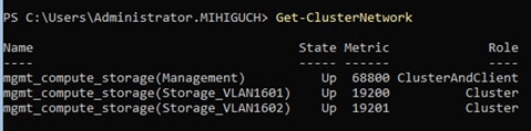
Azure Stack HCI Cluster Networks. The inside of an Azure Stack HCI server has the following network components:
● SET Switch: This is a virtual switch with embedded teaming capabilities. The SET switch provides teaming capabilities for network traffic that does not use the SMB-Multichannel. SMB Direct (RDMA) traffic uses SMB-Multichannel* to take advantage of the available network connections for bandwidth and redundancy instead of the teaming feature in the SET switch.
● Guest Partition: The tenant virtual machines run in the guest partition on the Hyper-V host. Each virtual machine runs in isolation from others and does not have direct access to the physical hardware in the host. Network connectivity is provided to the tenant virtual machine by connecting synthetic NIC in the virtual machine to the SET switch on the host.
● Parent Partition: The parent partition is the host operating system that runs the virtualization management stack and has access to the physical server hardware. The parent partition has one management vNIC and two storage vNICs as shown in the example below. An optional dedicated vNIC for backup operations can be added. if needed.
* SMB Multichannel is part of the Server Message Block (SMB) 3.0 protocol, which increases the network performance and the availability of file servers. SMB Multichannel enables file servers to use multiple network connections simultaneously.
The following diagrams illustrate a logical network diagram within an Azure Stack HCI server. In this example, Storage A and Storage B are for the parent partition only, whereas management network is available for both parent partition and VMs in the guest partition. By default, the “Allow management operating system to share this network adapter” option is enabled on vNIC on the SET switch. In this example, it’s enabled on the management vNIC (Yellow) whereas it’s disabled on the storage vNICs (Green and Purple).
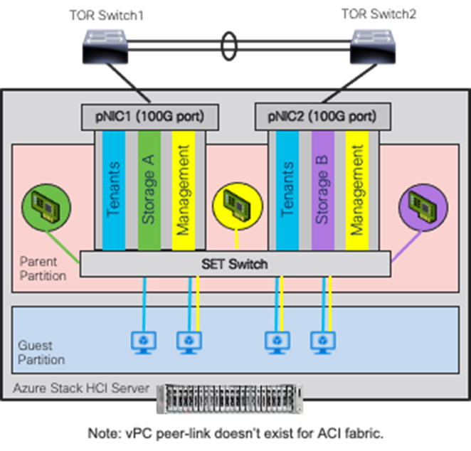
Azure Stack HCI Logical Architecture (SET Switch, Guest, and Parent Partitions)
MAC addresses for the VM virtual NICs are dynamically assigned, and the SET switch selects one of the available uplinks (physical NICs on the server) based on the source MAC address. This behavior provides load balancing and fault tolerance. The following diagram illustrates an example of how traffic from virtual machine A with virtual NIC MAC-A uses physical NIC1 as the uplink whereas traffic from virtual machine B with virtual NIC MAC-B uses physical NIC2 as the uplink. If the path using physical NIC1 is not available, all traffic goes through the other path.
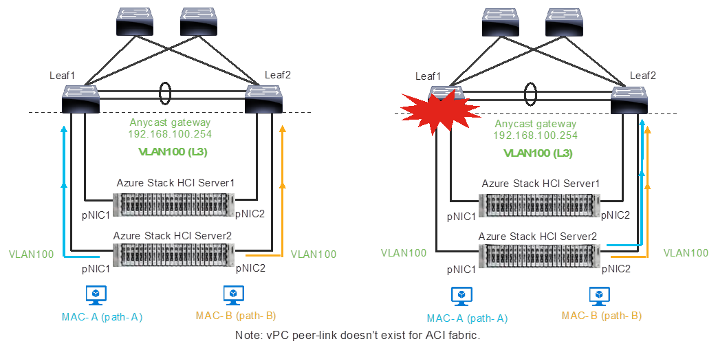
Load balancing behavior based on MAC address.
A consequence of this behavior is that some of the east-west network traffic that is not storage traffic transverses the spine (in the case of ACI) or vPC peer-link (in the case of NX-OS).
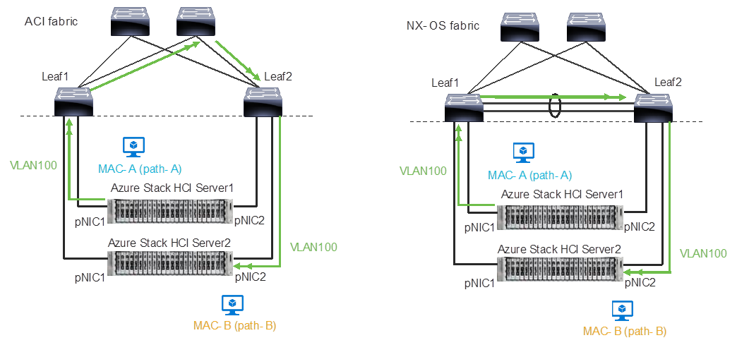
Traffic flow example
The network needs to allow the required traffic. Firewall requirements for Azure Stack HCI can be found at https://learn.microsoft.com/en-us/azure-stack/hci/concepts/firewall-requirements.
Cisco Nexus 9000 Series Switch based Fabric and Benefit
The table below lists the main features and benefits of the Nexus 9000 Series Switches based data center fabric.
Table 2. Features and Benefits
| Features |
Benefit |
ACI/NX-OS |
| Single point of Management |
The use of the controller (APIC or NDFC) provides single point of configuration management and policy definition, which simplifies the operational aspects of the fabric. |
ACI: APIC NX-OS: NDFC |
| Anycast Gateway |
The fabric operates as an anycast gateway for the VMs on Azure Stack HCI servers and other physical/virtual servers. Layer 3 gateway functionality is provided by ToR switches instead of core or aggregation switches. |
Both |
| VXLAN |
The use of the VXLAN provides seamless Layer 2 and Layer 3 connectivity between servers, independently from the physical Leaf location. It also provides multi-tenancy. |
Both |
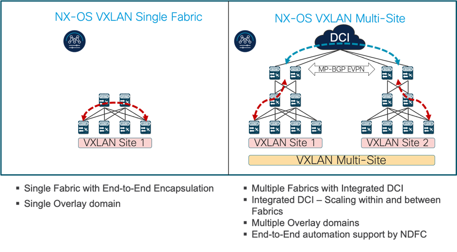
| Multi-Pod/Multi-Site |
Multi-Pod/Multi-Site fabric provides seamless Layer 2 and Layer 3 connectivity between endpoints, independently from the physical locations across data centers. |
ACI: Multi-Pod, Multi-Site and Remote Leaf NX-OS: Multi-Site |
| Service Chaining |
The use of Service Chaining capability provides flexible traffic redirection to L4-L7 service devices such as firewalls and load balancers. |
ACI: Service Graph PBR NX-OS: ePBR |
Figure 12
Cisco ACI connectivity options and policy domain evolution
Cisco Nexus 9000 Series Switch based Fabric and Benefit
Cisco ACI Design for Azure Stack HCI Connectivity
This section explains how Azure Stack HCI can connect to Cisco ACI by using the EPG and bridge domains.
This design assumes that the customer already has the Cisco ACI fabric in place with spine switches and APICs deployed and connected through a pair of leaf switches.
Cisco ACI for Azure Stack HCI Connectivity
The figure below illustrates the basic traffic flow of Azure Stack HCI traffic through the Cisco ACI fabric. In this design, the Cisco ACI fabric has two pairs of leaf nodes and two spine nodes, which are controlled by an APIC cluster. A pair of border leaf switches have the L3Out configured. This provides connection to a pair of external routers and thus to the Internet and Enterprise networks. Another pair of leaf nodes are connected to the Azure Stack HCI servers and other servers.
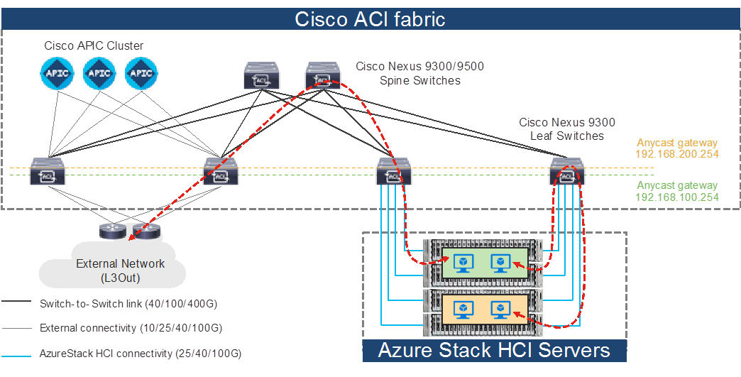
Azure Stack HCI Traffic flow via Cisco ACI Fabric
In this design, each leaf switch is connected to the Azure Stack HCI servers by using the 100GbE links. The two links between the ACI leaf switches and each Azure Stack HCI server are individual connections instead of a port-channel or vPC.
The figure below illustrates an ACI interface configuration example along with the domain and the VLAN pool configuration. Although it’s possible to use different interfaces on a pair of ToR switches, this document uses the same interfaces: node-101 (ethernet1/11 and 1/12) and node-102 (ethernet1/11 and 1/12). The figure below illustrates an ACI interface configuration example.

ACI leaf interface configuration for Azure Stack HCI servers
Azure Stack HCI ACI Tenant Model Overview
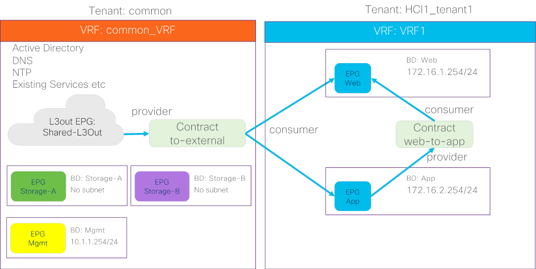
The figure 16 illustrates an example of a high-level relationship between various ACI tenant elements as deployed in the design by highlighting the Azure Stack HCI tenant. In this example, Azure Stack HCI tenant (HCI_tenant1) contains Virtual Routing and Forwarding (VRF), Bridge domains (BD), and end point groups (EPGs) for tenant networks, and the common tenant contains an external connectivity (L3Out) and EPGs for storage and management networks.
For Azure Stack HCI tenant networks to be able to communicate with other data center networks and access external networks, a contract must exist between the EPG in tenant HCI1_tenant1 and the other EPG in the same tenant and the external EPG (L3Out EPG) in the common tenant. For the EPGs in storage network A and B, the storage traffic is within its segment (BD), then there is no need to configure a contract with another EPG.
ACI Tenant Overview for Azure Stack HCI
In addition to the generic ACI configuration, the following configurations are required for the Azure Stack HCI network:
● Enable the required LLDP TLVs on the interfaces that are connected to the Azure Stack HCI servers
● QoS configuration for storage and cluster communication
For more information about configuring Cisco ACI and NDFC Fabric, see Solution Deployment.
Cisco NX-OS based Fabric Design for Azure Stack HCI Connectivity
This section explains how Azure Stack HCI can connect to Cisco Nexus 9000 Series Switches in the NX-OS mode.
You can use the Cisco Nexus 9000 NX-OS based VXLAN or the traditional classical LAN fabrics to connect to the Azure HCI environments. VXLAN leverages ECMP based multipathing over L3 links between the spine switches and Leaf switches and the traditional classic LAN fabric uses the L2 links (between Access and Aggregation devices) running STP. VXLAN is gaining more popularity and adoption for building data center fabrics because of its benefits over the traditional classical LAN.
VXLAN uses CLOS architecture where Leafs (also known as VTEP) are used to connect the end-host and performs origination and termination of VXLAN tunnels while Spine switches provide layer-3 connectivity between the Leaf switches.
Both these fabrics can be built and managed by Cisco NDFC. This enables faster and error-free deployment unlike the CLI-based approach that was used previously. Cisco NDFC supports various fabric templates to cater to any kind of data center fabric deployment. For the interest of Azure HCI, Data Center VLXAN EVPN and Enhanced Classic LAN fabric templates are the ones which should be used. This document describes the steps and workflows to connect Azure HCI to the VXLAN fabric.
Cisco NX-OS based Fabric for Azure Stack HCI Connectivity
The figure below illustrates the basic traffic flow of Azure Stack HCI traffic through the NX-OS based VXLAN fabric.
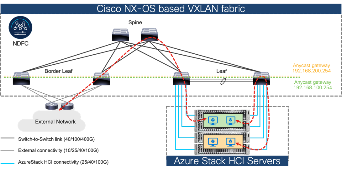
Azure Stack HCI Traffic flow through Cisco NX-OS based VXLAN fabric
In this design, a pair of leaf switches in vPC are connected to the Azure Stack HCI servers by using the 100 Gigabit Ethernet links. The two links between the leaf switches and each Azure Stack HCI server are individual connections instead of a port-channel or vPC.
This section provides a detailed procedure to configure the Cisco ACI and Cisco NDFC fabric to use in the environment. It also provides details about where the existing components are added as new components to an existing Cisco ACI or the Cisco NDFC fabric.
Note: Once the Cisco ACI or Cisco NDFC configuration is completed as per the procedure in this document, Azure Stack HCI cluster can be installed. Before you register the Azure Stack HCI, you can use the connectivity validator (Invoke-AzStackHciConnectivityValidation) on the Azure Stack HCI nodes or any other computer in the same network where you’ll deploy the Azure Stack HCI cluster. This validator checks the network connectivity that is required to register the Azure Stack HCI cluster to Azure.
Note: The Cisco ACI or Cisco NDFC fabric deployment and the automated installation of Azure Stack HCI are not part of this document.
Table 3 lists the hardware and software versions that are used in this solution.
Table 3. Hardware and Software Versions
| Layer |
Device |
Software version |
Comments |
|
Cisco ACI
|
Cisco APIC |
6.0 (3e) |
ACI Controller |
|
|
Cisco Nexus Switches in ACI Mode |
16.0(3e) |
ACI Spine and Leaf switches |
|
Cisco NX-OS
|
Cisco NDFC |
12.1.3b |
NDFC |
|
|
Cisco Nexus Switches in NX-OS mode |
10.2(3F) |
ToR switches |
|
Cisco Azure Stack HCI
|
|
2022H2 |
Azure Stack HCI release (Includes individual releases of software for all the devices that are part of Azure Stack HCI) |
Cisco ACI Configuration for Azure Stack HCI
This section explains how to configure Cisco ACI for Azure Stack HCI servers with the assumption that the ACI fabric and APICs already exists in the customer’s environment. This document does not cover the configuration required to bring the initial ACI fabric online.
The following are the configuration steps to configure Cisco ACI for Azure Stack HCI Servers:
● Configuring leaf interfaces connected to Azure Stack HCI servers
● Configure QoS
● Configure EPGs
Configuring Leaf Interfaces Connected to Azure Stack HCI Servers
This section contains the following steps:
● Create VLAN Pool for Azure Stack HCI Physical Domain
● Configure Physical Domain for Azure Stack HCI
● Create Attachable Access Entity Profile for Azure Stack HCI Physical Domain
● Create LLDP policy to enable the required TLVs for Azure Stack HCI
● Create Interface Priority Flow Control Policy to enable the required TLVs for Azure Stack HCI
● Create Interface Policy Group for Interfaces connected to Azure Stack HCI servers
● Associate the Interface Policy Group to the leaf interfaces connected to Azure Stack HCI servers
In figure 18 and table 4, summarizes the topology, interface, and physical domain configuration parameters that are used in this section. The connection uses four 100GbE interfaces between ACI Leaf switches and Azure Stack HCI servers.
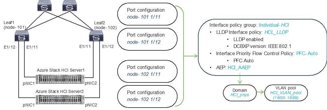
Interface and physical domain configuration for Azure Stack HCI Servers
Table 4. Interface and physical domain configuration for Azure Stack HCI Servers
| Interface |
Interface Policy Group |
LLDP Interface Policy |
Interface PFC Policy |
AAEP Name |
Domain Name |
Domain type |
VLAN Pool |
|
Leaf1 and Leaf2 Ethernet 1/11-12
|
Individual-HCI |
HCI_LLDP (DCBXP: IEEE 802.1) |
PFC-Auto |
HCI_AAEP |
HCI_phys |
Physical |
HCI_VLAN_pool (VLAN 1600-1699) |
Tables 5 and 6 summarize the common and the user tenant configuration parameters that are used in this section. The ACI Leaf switches serve as the gateway to the Azure Stack HCI networks except storage networks that are L2 only. Although contract names are listed for your reference, the Shared L3Out configuration in common tenant and contract configuration steps are not covered in this document.
Tenant configuration example
Table 5. Azure Stack HCI common tenant configuration example
| Property |
Name |
| Tenant |
common |
| Tenant VRF |
common_VRF |
| Bridge domains |
Storage-A in common_VRF (No subnet) Storage-B in common_VRF (No subnet) Mgmt in common_VRF (10.1.1.254/24) |
| Leaf nodes and interfaces |
Node 101 & 102 ethernet1/11 and 1/12 |
| EPGs |
EPG Mgmt in BD Mgmt (VLAN 1600) EPG Storage-A in BD Storage-A (VLAN 1601) EPG Storage-B in BD Storage-B (VLAN 1602) |
| External EPG (L3 Out) |
Shared_L3Out in common tenant |
| Contract |
Allow-Shared-L3Out provided by common tenant |
Table 6. Azure Stack HCI tenant configuration example
| Property |
Name |
| Tenant |
HCI_tenant1 |
| Tenant VRF |
VRF1 |
| Bridge domain |
BD1 (192.168.1.254/24) in VRF1 |
| Leaf nodes and interfaces |
Node 101 & 102 ethernet1/11 and 1/12 |
| EPGs |
Web EPG in BD1 (VLAN 1611) App EPG in BD1 (VLAN 1612) |
| Contract |
Allow-Shared-L3Out provided by common tenant Web-App contract defined in the tenant |
Create VLAN Pool for Azure Stack HCI Physical Domain
In this section, you create a VLAN pool to enable connectivity to the Azure Stack HCI.
To configure a VLAN pool to connect the Azure Stack HCI servers to the ACI Leaf switches, follow these steps:
1. From the APIC top navigation menu, select Fabric > Access Policies.
2. From the left navigation pane, expand and select Pools > VLAN.
3. Right-click and select Create VLAN Pool.
4. In the Create Pool pop-up window, specify a Name (for example, HCI_VLAN_pool) and for Allocation Mode, select Static Allocation.
5. For Encap Blocks, use the [+] button on the right to add VLANs to the VLAN Pool. In the Create Ranges pop-up window, configure the VLANs that need to be configured from the Leaf switches to the Azure Stack HCI servers. Leave the remaining parameters as is.
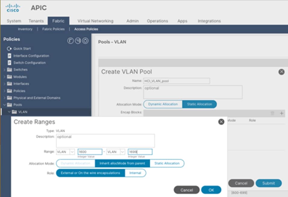
6. Click OK.
7. Click Submit.
Configure Physical Domain for Azure Stack HCI
To create a physical domain type, connect to Azure Stack HCI servers, follow these steps:
1. From the APIC top navigation menu, select Fabric > Access Policies.
2. From the top navigation menu, select Fabric > Access Policies.
3. From the left navigation pane, expand and select Physical and External Domains > Physical Domains.
4. Right-click Physical Domains and select Create Physical Domain.
5. In the Create Physical Domain pop-up window, specify a Name for the domain (for example, HCI_phys). For the VLAN Pool, select the previously created VLAN Pool (for example, HCI_VLAN_pool) from the drop-down list.
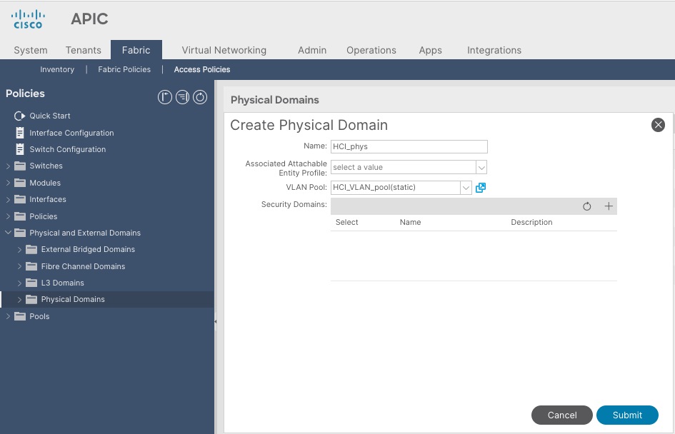
6. Click Submit.
Create Attachable Access Entity Profile for Azure Stack HCI Physical Domain
To create an Attachable Access Entity Profile (AAEP), follow these steps:
1. From the APIC top navigation menu, select Fabric > Access Policies.
2. From the left navigation pane, expand and select Policies > Global > Attachable Access Entity Profiles.
3. Right-click and select Create Attachable Access Entity Profile.
4. In the Create Attachable Access Entity Profile pop-up window, specify a Name (for example, HCI_AAEP) and uncheck “Enable Infrastructure VLAN” and “Association to Interfaces”.
5. For the Domains, click the [+] on the right-side of the window and select the previously created domain from the drop-down list below Domain Profile.
6. Click Update.
7. You should now see the selected domain and the associated VLAN Pool as shown below.
8. Click Next. This profile is not associated with any interfaces at this time because “Association to Interfaces” is unchecked at step 4 above. They can be associated once the interfaces are configured in an upcoming section.
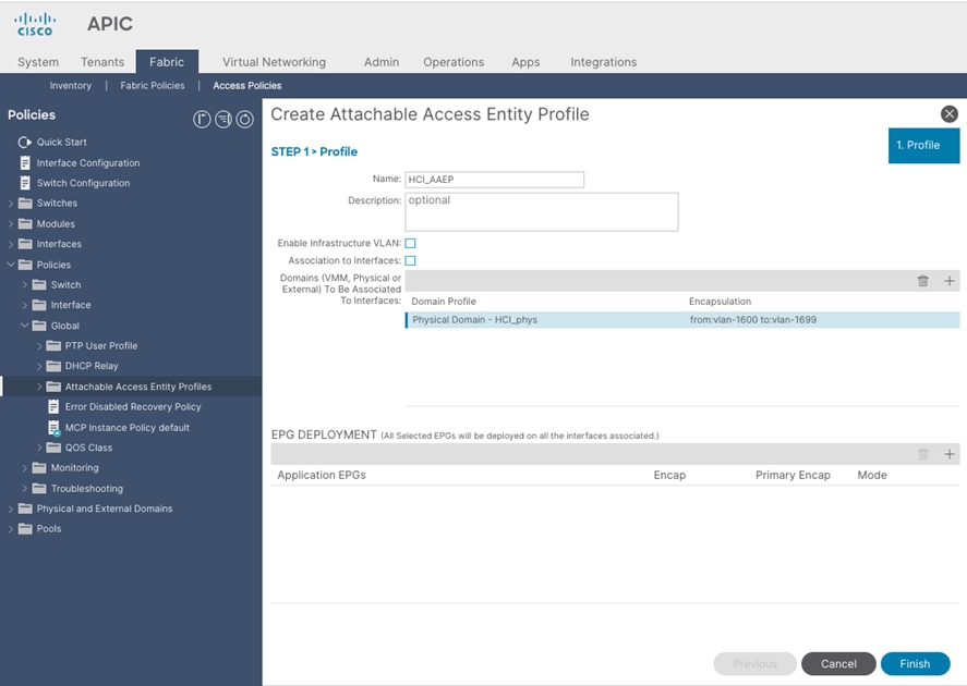
9. Click Finish.
Create LLDP policy to Enable the Required TLVs for Azure Stack HCI
To create an LLDP policy to enable the required TLVs for Azure Stack HCI, follow these steps:
1. From the APIC top navigation menu, select Fabric > Fabric Policies.
2. From the left navigation pane, expand and select Policies > Global > LLDP policy by default.
3. Check the following optional TLVs:
i. DCBX (for storage network)
ii. Port Link Aggregation
iii. Port Maximum Frame Size
iv. Port VLAN Name
Note: Port VLAN, that is also required for Azure Stack HCI, is always enabled regardless LLDP policy configuration.
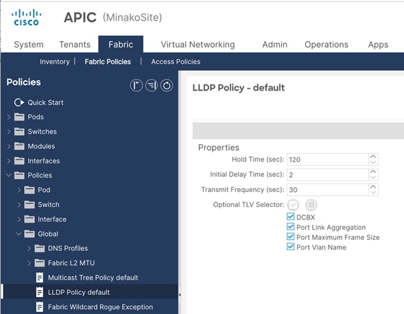
4. Click Submit.
Create LLDP Interface Policy
To create an LLDP policy to enable the required TLVs for Azure Stack HCI, follow these steps:
1. From the APIC top navigation menu, select Fabric > Access Policies.
2. From the left navigation pane, expand and select Policies > Interfaces > LLDP Interfaces.
3. Right-click and select Create LLDP Interface Policy.
4. In the Create LLDP Interface Policy pop-up window, specify a Name (for example, HCI_LLDP).
5. Select Enable for Transmit State
6. Select IEEE 802.1 for DCBXP Version.
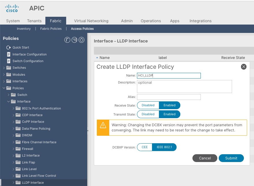
7. Click Submit.
Create Interface Priority Flow Control Policy
To create an interface policy group to enable PFC on leaf downlinks, follow these steps:
1. From the APIC top navigation menu, select Fabric > Access Policies.
2. From the left navigation pane, expand and select Policies > Interface > Priority Flow Control
3. Right-click and select Create Priority Flow Control Policy.
4. In the Create Priority Flow Control Policy pop-up window, specify a Name (for example PFC-Auto) and select Auto. (To include PFC configuration state via DCBX protocol, it needs to be set to Auto.)
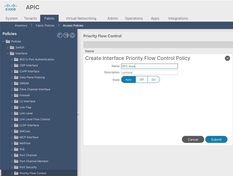
5. Click Submit.
Create Interface Policy Group for Interfaces connected to Azure Stack HCI servers
To create an interface policy group to connect to external gateways outside the ACI fabric, follow these steps:
1. From the APIC top navigation menu, select Fabric > Access Policies.
2. From the left navigation pane, expand and select Interfaces > Leaf Interfaces > Policy Groups > Leaf Access Port.
3. Right-click and select Create Leaf Access Port Policy Group.
4. In the Create Leaf Access Port Policy Group pop-up window, specify a Name (for example Individual-HCI) and the applicable interface policies from the drop-down list for each field.
5. For the Attached Entity Profile, LLDP Policy and Priority Flow Control fields, select the previously created AAEP, LLDP policy and Priority Flow Control policy (for example, HCI_AAEP, HCI_LLDP and PFC-auto).
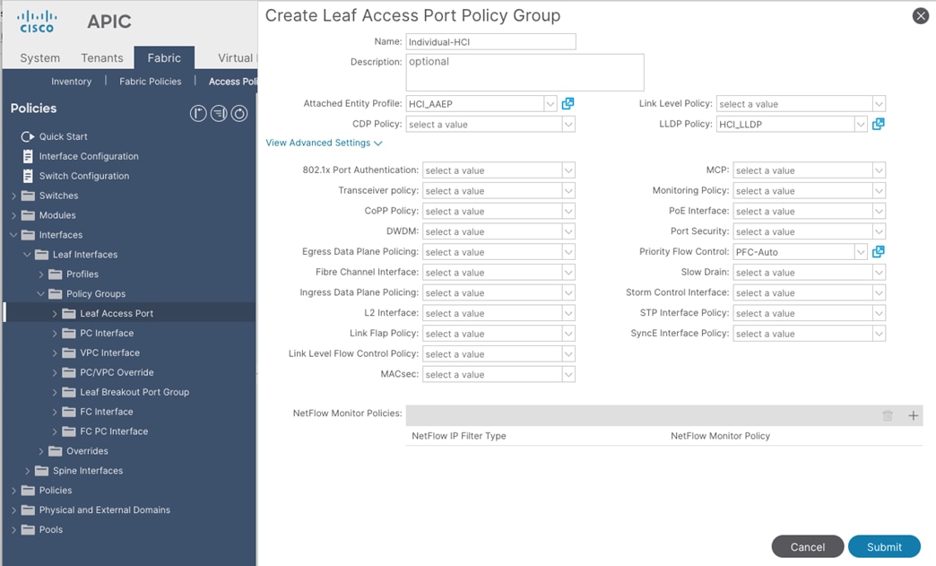
6. Click Submit.
Associate the Interface Policy Group to the Leaf Interfaces Connected to Azure Stack HCI servers
To configure leaf interfaces connected to Azure Stack HCI servers, follow these steps:
1. From the APIC top navigation menu, select Fabric > Access Policies.
2. From the left navigation pane, select Interface Configuration.
3. From the right pane, right-click Actions and select Configure Interfaces.
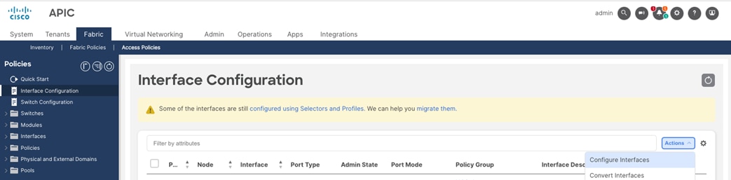
4. In the Configure interfaces window, select the following options.
i. Node Type: Leaf
ii. Port Type: Access
iii. Interface Type: Ethernet
iv. Interface Aggregation Type: Individual
5. Click Select Node. In the Select Nodes pop-up window, select leaf nodes to connect Azure Stack HCI servers (for example, Node 101-102) and click OK.
6. Specify the Leaf interfaces to connect Azure Stack HCI servers (for example, 1/11-12).
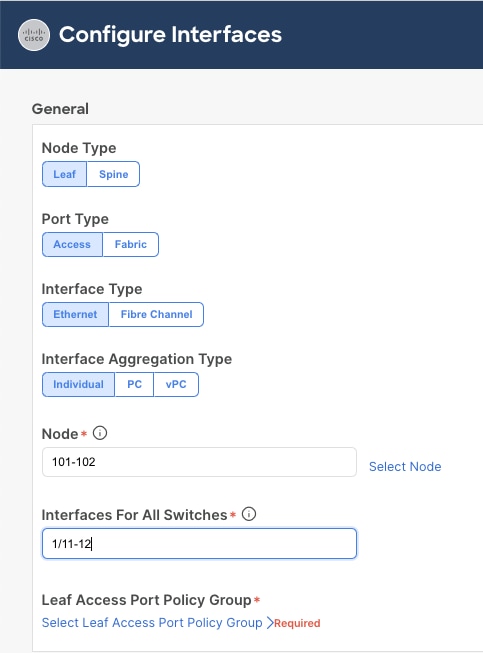
7. Click Select Leaf Access Port Policy Group. In the Select Leaf Access Port Policy Group pop-up window, select the previously created Leaf Access Port Policy Group (for example, Individual-HCI) from the list, and click Select.
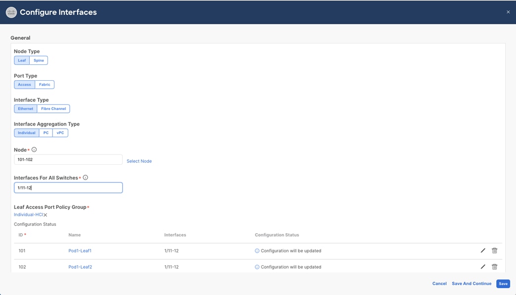
8. Click Save.
The table below summarizes the host network QoS recommendation from Microsoft. Please refer to the Microsoft document for details: https://learn.microsoft.com/en-us/azure-stack/hci/concepts/host-network-requirements.
Table 7. Azure Stack HCI host network QoS recommendation
|
|
Cluster Communication Traffic |
Storage traffic |
Default (Tenant and Management Networks) |
| Purpose |
Bandwidth reservation for cluster heatbeats |
Bandwidth reservation for lossless RDMA communication for Storage Spaces Direct |
For all other traffic such as tenant networks.
|
| Flow Control (PFC enabled) |
No |
Yes |
No |
| Bandwidth reservation |
1% for 25GbE or higher RDMA networks 2% for 10GbE or lower RDMA networks |
50% |
Default (no host configuration required) |
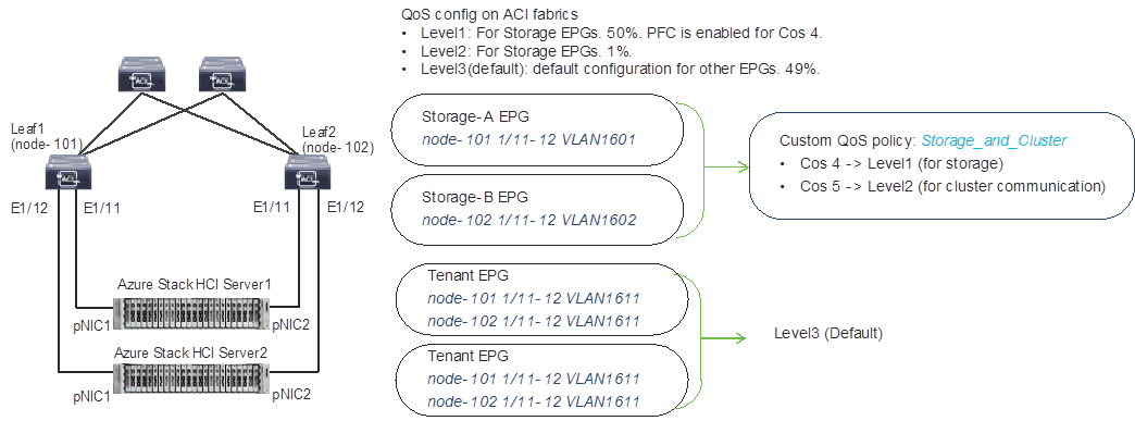
Based on the recommendation, this document uses the following ACI QoS configurations as an example, which are the same as the bandwidth reservation and Priority configurations that are used in the Cisco UCS C240 M6 Solution for Microsoft Azure Stack HCI.
· Level1 for RDMA (storage) traffic (Traffic comes with Cos 4 marked by Azure Stack HCI)
o PFC is enabled
o Bandwidth reservation: 50%
o ETS (Weighted round robin in ACI)
· Level2 for cluster communication (Traffic comes with Cos 5 marked by Azure Stack HCI)
o PFC is not enabled
o Bandwidth reservation: 1%
o ETS (Weighted round robin in ACI)
· Level3(default) for VM traffic and management traffic (Other traffic)
o PFC is not enabled
o Bandwidth reservation: 49%
o ETS (Weighted round robin in ACI)
The figure below illustrates an example of QoS configuration.

ACI QoS configuration for Azure Stack HCI
The Cisco ACI fabric supports six user-configurable QoS levels (Level1-6) as well as two levels reserved for fabric control traffic, SPAN, and traceroute traffic.
Table 8. Cisco ACI QoS Levels
| Class of Service |
QoS Group Used by DCBX (ETS configuration and ETS recommendation) * |
Traffic Type |
Doc1p (Cos) Marking in VXLAN Header |
DEI Bit** |
| 0 |
0 |
Level 3 (default) |
0 |
0 |
| 1 |
1 |
Level 2 |
1 |
0 |
| 2 |
2 |
Level 1 |
2 |
0 |
| 4 |
7 |
Level 6 |
2 |
1 |
| 5 |
6 |
Level 5 |
3 |
1 |
| 6 |
5 |
Level 4 |
5 |
1 |
| 3 |
3 |
APIC Controller |
3 |
0 |
| 9 |
Not Advertised |
SPAN |
4 |
0 |
| 8 (SUP) |
4 |
Control |
5 |
0 |
| 8 (SUP) |
4 |
Traceroute |
6 |
0 |
| 7 |
Not Advertised |
Copy Service |
7 |
0 |
* In IEEE DCBX PFC configuration LLDP TLV, the Priority value is the associated Cos value regardless of which Level (Level 1-6) the PFC is enabled. The configuration section below includes an example.
**The Drop Eligible Indicator (DEI) bit is a 1-bit field that is used to indicate frames that are eligible to be dropped during traffic congestion. The CoS value (3 bits) + DEI value (1 bit) represents the QoS class.
Configure QoS Classes
To configure Cisco ACI QoS classes, follow these steps:
1. From the APIC top navigation menu, select Fabric > Access Policies.
2. From the left navigation pane, expand Policies > Global > QoS Class and select one of the levels. (For example, level1 for storage traffic).
3. In the Scheduling algorithm field, from the drop-down list, choose Weighted round robin. This is the default configuration.
4. In the Bandwidth allocation (in %) field, specify a number. (For example, 50 for storage traffic).
5. If PFC is not required in the class, leave PFC Admin State field unchecked.
6. If PFC is required in the class,
a. Check PFC Admin State field
b. In the No Drop-Cos field, select Cos value (For example, Cos 4 for storage traffic)
c. In the scope field, select Fabric-wide PFC. (If the traffic is within the same leaf, IntraTor PFC is also fine)
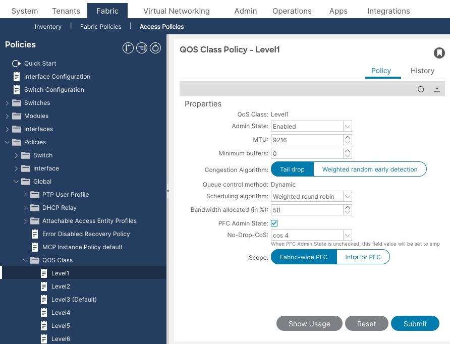
7. Click Submit.
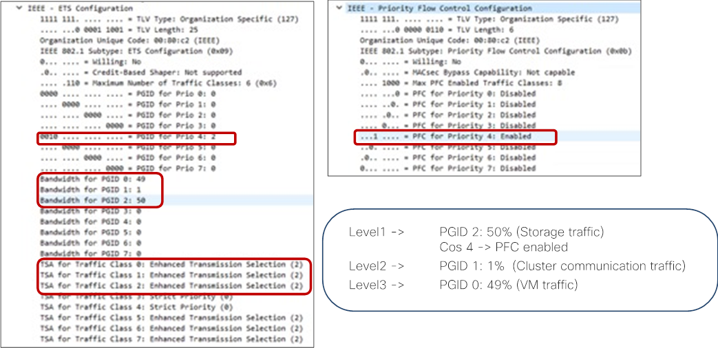
With this QoS configuration and LLDP IEEE DCBX configuration, the following values are set in LLDP.
· IEEE ETS Configuration and IEEE ETS Recommendation
o PGID for Prio 4: 2 (because Cos 4 is selected and level1 is QoS group 2)
o Bandwidth for PGID 2: 50 (level1 is QoS group 2)
o TSA for Traffic Class 2: Enhanced Transmission Selection (level1 is QoS group 2)
· IEEE Priority Flow Control Configuration
o PFC for Priority 4: Enabled (because Cos 4 is selected, and PFC is enabled)
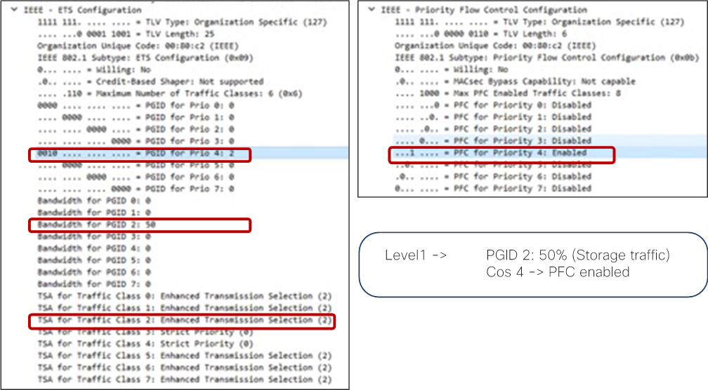
By default, all “PGID for Pri 0” to “PGID for Pri 7” are set to 0 and all “PFC for Priority 0” to “PFC for Priority 7” are set to Disabled. If PFC is enabled, the value for the specific priority (Cos value) is updated. (“PGID for Pri 4: 2” and “PFC for Priority 4” in the example above.)
8. Repeat step 2 –7 for the level for cluster communication traffic. For example, level2 for cluster communication traffic with 1% bandwidth reservation configuration is the following:
● QoS Class: level2
● Scheduling algorithm: Weighted round robin (default configuration)
● Bandwidth allocation (in %): 1
● PFC Admin State: unchecked
With this QoS configuration and LLDP IEEE DCBX configuration, the following values are set in LLDP. There is no change on PGID and PFC for Priority 0-3 and 5-7.
● IEEE ETS Configuration and IEEE ETS Recommendation
a. Bandwidth for PGID 1: 1 (because level2 is QoS group 1 based on table 8)
b. TSA for Traffic Class 1: Enhanced Transmission Selection
9. Repeat step 2 –7 for the level other traffic. For example, level3(Default) for VM traffic with 49% bandwidth reservation configuration is the following:
● QoS Class: level3(Default)
● Scheduling algorithm: Weighted round robin (default configuration)
● Bandwidth allocation (in %): 49
● PFC Admin State: unchecked
With this QoS configuration and LLDP IEEE DCBX configuration, the following values are set in LLDP. There is no change on PGID and PFC for Priority 0-3 and 5-7.
● IEEE ETS Configuration and IEEE ETS Recommendation
a. Bandwidth for PGID 0: 10 (because level3 is QoS group 0 based on table 8)
b. TSA for Traffic Class 0: Enhanced Transmission Selection
Configure Custom QoS Policy
ACI has multiple QoS classification options that are illustrated in the figure below.
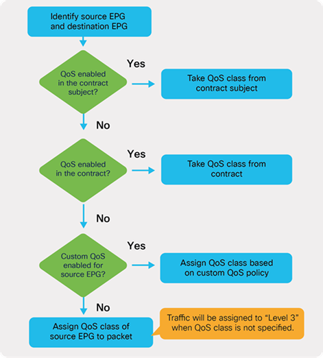
ACI QoS configuration priority
This document uses QoS Class configuration at EPGs for tenant and management networks (default level3),and uses the custom QoS policy configuration at EPG for storage and cluster communication network (level1 for storage with Cos 4 and level2 for cluster communication with Cos 5).
ACI QoS and EPG configuration example
To configure a Custom QoS policy, follow these steps:
1. From the APIC top navigation menu, select Tenants > common (or select an existing tenant where you want to configure EPGs).
2. From the left navigation pane, expand and select Policies > Protocol > Custom QoS.
3. Right-click and select Create Custom QoS Policy to open the Create Custom QOS Policy pop-up window.
4. In the Name field, specify a Name (for example, Storage_and_Cluster).
5. In the Dot1P Classifiers field, click + and configure the followings:
a. Priority (In this example, select level2 from the drop-down list for storage traffic)
b. Dot1P Range From and To (In this example, specify 4 for storage traffic)
6. Click Update.
7. Repeat step 5-6 for cluster communication traffic. (In this example, level1 with 5 for cluster communication traffic.)
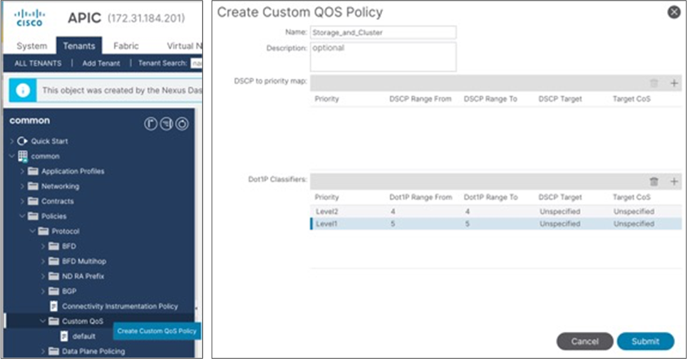
8. Click Submit.
This Custom QoS Policy is referred to in the next step (Configuring EPGs)
The following EPGs are created in this section.
● Tenant EPGs for VMs
● Management EPG for management network
● Storage EPGs for storage networks
● Configure contracts
● Add consumer and provider EPGs to the contract
Configure Tenant EPGs
To configure a tenant EPG for Azure Stack HCI VMs, follow these steps:
1. From the APIC top navigation menu, select Tenants > Add Tenant
2. In the Create Tenant dialog box, specify a Name (for example, HCI_tenant1).
3. In the VRF Name field, enter the VRF name (for example, VRF1).
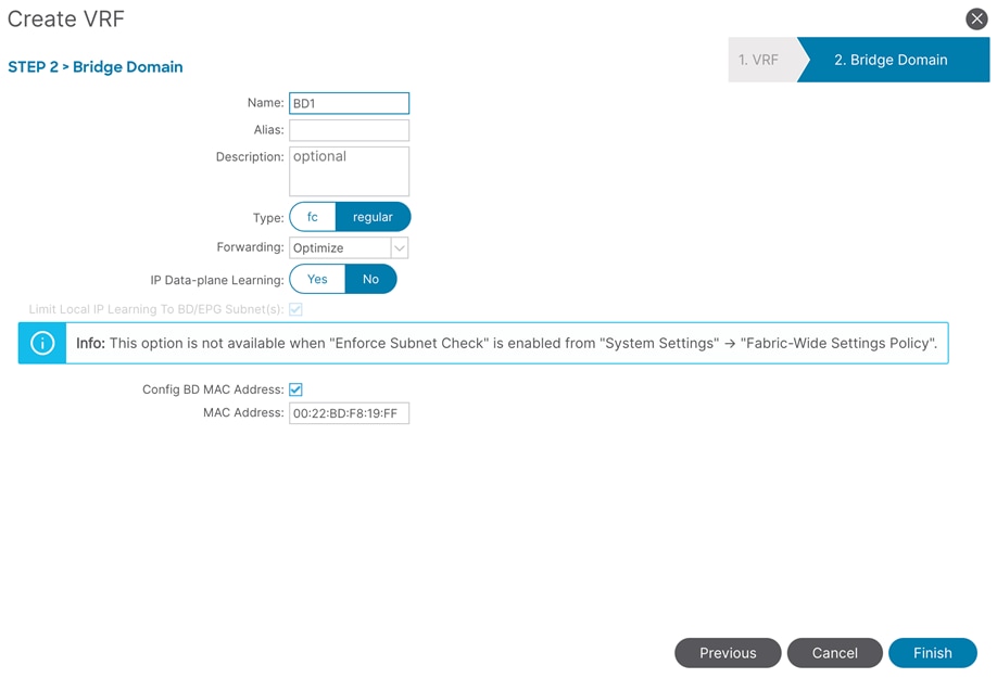
4. Check Create A Bridge Domain and click Next.
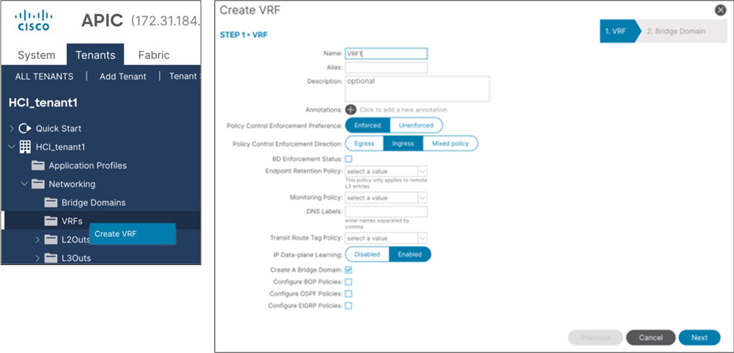
5. In the Name field, specify a Name (for example, BD1) and click Finish.
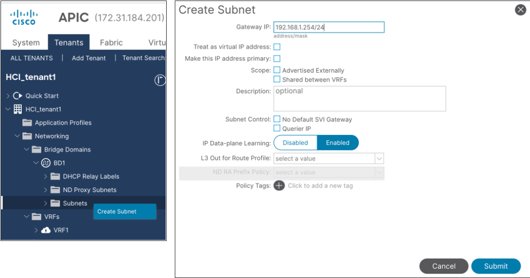
6. To create an anycast gateway IP address on the bridge domain, in the Navigation pane, expand the created bridge domain (BD1) under Networking > Bridge Domains.
7. Right-click Subnets and choose Create Subnet.
8. In the Gateway IP field, configure the anycast gateway IP address (In this example, 192.168.1.254/24), and click Submit.
9. To create an Application Profile, from the left navigation pane, right-click Application Profiles and choose Create Application Profile.
10.In the Name field, specify a Name (for example, AP1) and click Submit.
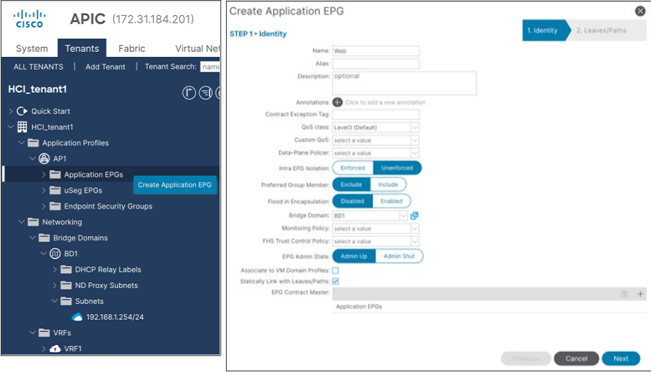
11.To create an EPG, from the left navigation pane, expand the created Application Profile, right-click Application EPGs and choose Create Application EPG.
12.In the Name field, specify a Name (for example, Web).
13.In the QoS class field, from the drop-down list, choose a Level. (for example, Level3 (Default) for VM traffic, which is the default configuration)
14.In the Bridge Domain field, from the drop-down list, choose the BD we created (In this example, BD1).
15.Check Statically Link with Leaves/Paths and click Next.
Note: QoS class is Level3 (Default) for the tenant EPG, which doesn’t enable PFC by default.
16.In the Physical Domain field, from the drop-down list, choose the physical domain we created (In this example, HCI_phys).
17.In the Paths field, click + and select a Path and configure Port Encap. (In this example, Pod-1/Node-101/eth1/11 and vlan-1611 for Web).
18.Repeat step 17 to add all the interfaces that are connected to Azure Stack HCI servers in the cluster. (In this example, Node-101/eth1/11-12 and Node-102/eth1/11-12 with vlan-1611 for Web).
19.Repeat step 11-18 for other tenant EPGs (for example, EPG App with vlan-1612).
Configure a Management EPG
To configure Azure Stack HCI storage networking, follow these steps:
1. From the APIC top navigation menu, select Tenants > common (or select an existing tenant where you want to configure a management EPG).
2. From the left navigation pane, expand and select Networking > Bridge Domains.
3. Right-click and select Create Bridge Domain.
4. In the Name field, specify a Name (for example, Mgmt) and select a VRF name (in this example, common-VRF).
5. Click Next.
6. In the Subnets field, click + to create subnet.
7. In the Gateway IP field, specify an IP (for example, 10.1.1.254/24).
8. Click OK.
9. To create an EPG, from the left navigation pane, expand Application Profiles and select an existing Application Profile (or create a new Application Profile).
10.Right-click Application EPGs and select Create Application EPG.
11.In the Name field, specify a Name (for example, Mgmt).
12.the QoS class field, from the drop-down list, choose a Level. (for example, Level3(Default) for management traffic).
13.In the Bridge Domain field, from the drop-down list, choose the BD we created (In this example, Mgmt).
14.Check Statically Link with Leaves/Paths and click Next.
15.In the Physical Domain field, from the drop-down list, choose the physical domain we created (In this example, HCI_phys).
16.In the Paths field, click + and select a Path and configure Port Encap (In this example, Pod-1/Node-101/eth1/11 and vlan-1600 for Mgmt). If native VLAN (untagged) is used for management network, select Trunk (Native) in the Mode field.
17.Repeat step 16 for other Azure Stack HCI server interfaces in the cluster. (In this example, Node-101/eth1/11-12 and Node-102/eth1/11-12 with vlan-1600 for Mgmt).
Configure Storage EPGs
To configure Azure Stack HCI storage networking, follow these steps:
1. From the APIC top navigation menu, select Tenants > common (or select an existing tenant where you want to configure storage EPGs).
2. From the left navigation pane, expand and select Networking > Bridge Domains.
3. Right-click and select Create Bridge Domain.
4. In the Name field, specify a Name (for example, Storage-A) and select a VRF name (In this example, common-VRF).
5. In the Forwarding field, from the drop-down list, choose Custom.
6. In the L2 Unknown Unicast field, from the drop-down list, choose Flood.
7. Click Next.
8. Uncheck Unicast Routing checkbox to disable Unicast Routing and click Next.
9. Click Finish.
10.To create an EPG, from the left navigation pane, expand Application Profiles and select an existing Application Profile (or create a new Application Profile).
11.Right-click Application EPGs and select Create Application EPG.
12.In the Name field, specify a Name (for example, Storage-A).
13.In the Custom QoS field, from the drop-down list, choose the Custom QOS Policy we created (In this example, Storage_and_Cluster).
14.In the Bridge Domain field, from the drop-down list, choose the BD we created (In this example, Storage-A).
15.Check Statically Link with Leaves/Paths and click Next.
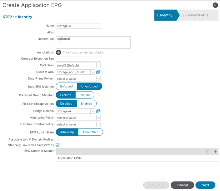
16.In the Physical Domain field, from the drop-down list, choose the physical domain we created (In this example, HCI_phys).
17.In the Paths field, click + and select a Path and configure Port Encap (In this example, Pod-1/Node-101/eth1/11 and vlan-107 for Storage-A).
18.Repeat step 17 for other Azure Stack HCI servers in the cluster (In this example, Pod-1/Node-102/eth1/11 and vlan-107 for Storage-A).
19.Repeat step 2-21 for the second storage EPG (for example, Storage-B and EPG Storage-B using the created Custom QoS Storage_and_Cluster, physical domain HCI_phys and Path Pod-1/Node-101/eth1/12 and Pod-1/Node-102/eth1/12 with vlan-207).
Configure Contracts
To configure a contract, follow these steps:
1. From the APIC top navigation menu, select Tenants and select a tenant where the provider EPG resides. For example, select tenant HCI_tenant1 for a contract between Web and App EPGs.
2. From the left navigation pane, expand and select Contracts.
3. Right-click and select Create Contract.
4. In the Name field, specify a Name (for example, Web-to-App).
5. In the Scope field, from the drop-down list, choose a Scope (In this example, VRF. If it’s inter-tenant contract, select Global.)
6. In the Subjects field, click + and specify a contract subject name. (For example, Subject1.)
7. In the Filter field, click + and choose an existing filter (or create a new filter from the drop-down list).
8. Click Update and repeat step 7, if you have another filter.
9. Click OK.
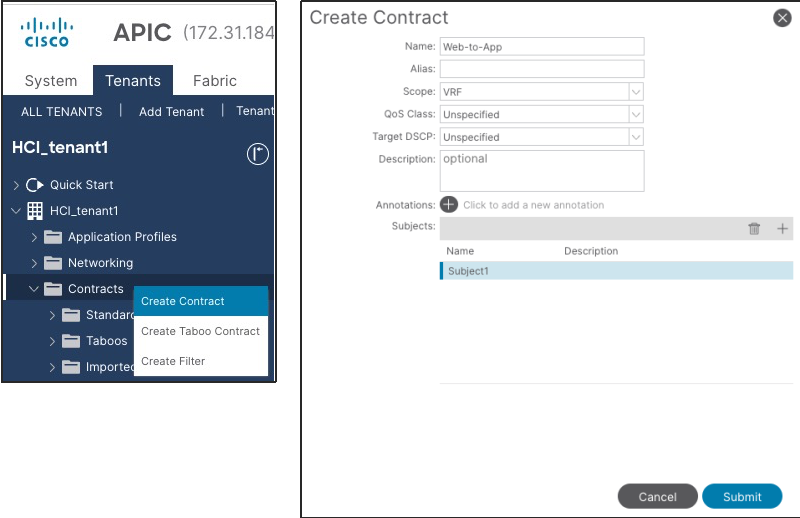
10.Click Submit.
11.Repeat step 1-10 if you have another contract.
Add Consumer/Provider EPGs to the contract
To add an EPG to a contract, follow these steps:
1. From the APIC top navigation menu, select Tenants and select a tenant where the EPG resides. For example, select tenant HCI_tenant1 for a contract between Web and App EPGs.
2. From the left navigation pane, expand Application Profiles and expand the Application Profile where the EPG resides.
3. Expand Application EPGs and expand the EPG. (For example, Web).
4. Right-click Contracts and select Add Provided Contract or Add Consumed Contract depending on whether the EPG is the provider or the consumer. (In this example, Web EPG is the consumer to the contract).
5. In the Contract field, from the drop-down list, choose the contract we created (In this example, Web-to-App).
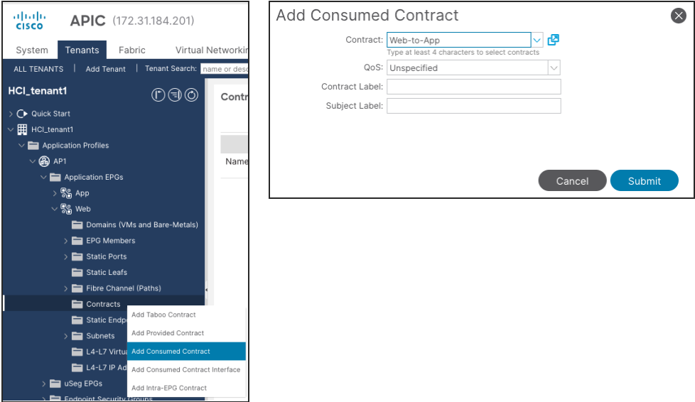
6. Click Submit.
7. Repeat step 1-6 for other EPGs.
Cisco NX-OS based Fabric configuration for Azure Stack HCI
This section explains how to configure Cisco NX-OS based VXLAN fabric for Azure Stack HCI servers with the assumption that the VXLAN fabric managed by Cisco NDFC already exists in the customer’s environment. This document does not cover the configuration required to bring the initial VXLAN fabric. For building IGP based Underlay and iBGP based Overlay (BGP EVPN), Data Center VXLAN EVPN fabric template should be used.
This document does not cover NX-OS based traditional classical LAN fabric however, the same workflow can be followed for traditional classical LAN fabrics. NDFC comes with Enhanced Classic LAN (ECL) fabric template for building NX-OS based traditional classical LAN fabrics.
The overall configuration can be categorized as below:
● Configure QoS
● LLDP configuration
● Configuring leaf interfaces connected to Azure Stack HCI servers
● Configuration of Networks and VRFs
● Configuring External connectivity
The QoS requirement for Azure Atack HCI host is same for both ACI and NX-OS based fabrics. For more details, please refer Table 7 Azure Stack HCI host network QoS recommendation.
Only the switches connected to Azure Stack HCI servers need to have the required QoS configurations as shown below:
Create Class-maps to classify RDMA and cluster communication traffic on ingress interface based on CoS markings set by the Azure Stack HCI servers -
class-map type qos match-all RDMA
match cos 4
class-map type qos match-all CLUSTER-COMM
match cos 5
Once the traffic is classified (based on CoS value set by the Server) it needs to be mapped to the respective QoS Groups -
policy-map type qos AzS_HCI_QoS
class RDMA
set qos-group 4
class CLUSTER-COMM
set qos-group 5
Define Network QoS classes and match traffic based on the QoS Groups -
class-map type network-qos RDMA_CL_Map_NetQos
match qos-group 4
class-map type network-qos Cluster-Comm_CL_Map_NetQos
match qos-group 5
Create Network QoS policy to enable PFC for RDMA traffic and set Jumbo MTU -
policy-map type network-qos QOS_NETWORK
class type network-qos RDMA_CL_Map_NetQos
pause pfc-cos 4
mtu 9216
class type network-qos Cluster-Comm_CL_Map_NetQos
mtu 9216
class type network-qos class-default
mtu 9216
Configure Queuing policy to enable ECN for RDMA traffic and bandwidth allocation for other classes -
policy-map type queuing QOS_EGRESS_PORT
class type queuing c-out-8q-q-default
bandwidth remaining percent 49
class type queuing c-out-8q-q1
bandwidth remaining percent 0
class type queuing c-out-8q-q2
bandwidth remaining percent 0
class type queuing c-out-8q-q3
bandwidth remaining percent 0
class type queuing c-out-8q-q4
bandwidth remaining percent 50
random-detect minimum-threshold 300 kbytes maximum-threshold 300 kbytes drop-probability 100 weight 0 ecn
class type queuing c-out-8q-q5
bandwidth percent 1
class type queuing c-out-8q-q6
bandwidth remaining percent 0
class type queuing c-out-8q-q7
bandwidth remaining percent 0
Apply the Queuing and Network QoS policies to System QoS -
system qos
service-policy type queuing output QOS_EGRESS_PORT
service-policy type network-qos QOS_NETWORK
The above QoS configuration is only required on the Leaf switches that are used to connect Azure Stack HCI servers. There is no requirement of fabric-wide QoS configuration as long as all the Azure Stack HCI servers of same cluster are connected to same vPC pair of Leafs.
The steps to configure the QoS policies through NDFC are as follows:
Step 1: Select both the Leaf switches (connecting to Azure Stack HCI) and create a Group Policy using switch_freefrom policy template and paste all the QoS related configuration (shown above) in Switch Freeform Config box.
To create a policy, go to Fabric Detailed View > Policies Tab.
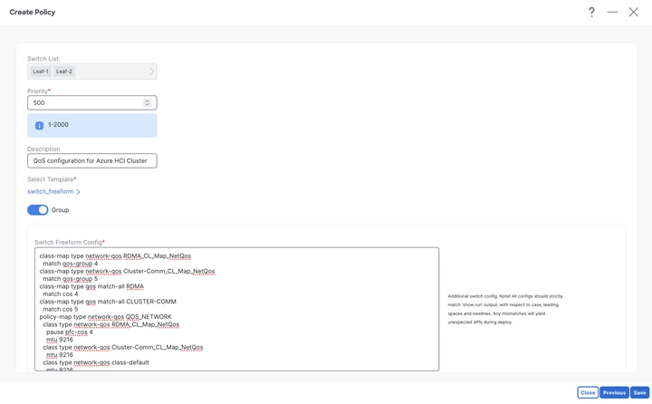
Click on Save and you would be returned to Policy tab. From Policy tab page select the policy just created and click on Push button from Actions drop-down to deploy generated config to the Leaf switches
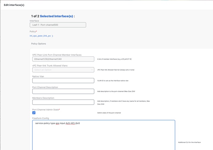
Step 2: Apply the QoS policy on the Peer-link of Leaf switches (connecting to Azure HCI).
This is required to apply QoS on any traffic which may pass over the peer-link.
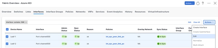
From Fabric Overview > Interfaces tab, select the peer-link port-channel interfaces for Leaf-1 and Leaf-2 and click on Edit from Actions drop-down.
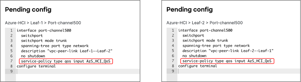
Click on Save button for Leaf-1.
Click on Next button and repeat the same step for vPC peer-link of Leaf-2.
Verify the pending configuration and deploy.
Step 3: Apply the QoS policy on Leaf switch interfaces which are used to connect to Azure HCI.
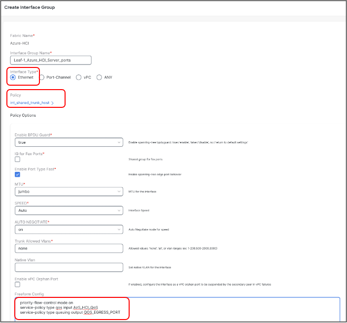
Cisco NDFC allows grouping the interfaces using Interface Groups. All the interfaces which require identical configuration can be grouped together using an Interface Group and all the required configuration is applied only to the Interface Group.
Although Leaf-1 and Leaf-2 interfaces connecting to Azure Stack HCI server require same QoS configuration, they would be carrying different VLANs for RDMA traffic (Leaf-1 for Storage-A and Leaf-2 for Storage-B) therefore two separate Interface Groups are required.
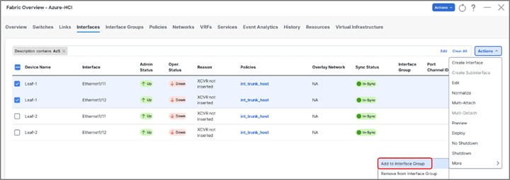
Ports Eth1/11-12 are added to Leaf-1_Azure_HCI_Server_ports Interface Group with following settings:
● Set Interface Type: Ethernet
● Policy: int_ethernet_trunk_host
● Enable BPDU Guard: True
● Enable Port Type Fast: Yes
● MTU: Jumbo (9216 bytes)
● Native VLAN: Can be set to Mgmt Vlan (Optional)
● Freefrom Config: Provide service-policy CLI command to apply QoS and Queuing policies and CLI command to enable Policy Flow Control to the interfaces
Repeat the above steps for adding Leaf-2 ports Eth1/11-12 to Leaf-2_Azure_HCI_Server_ports Interface Group -
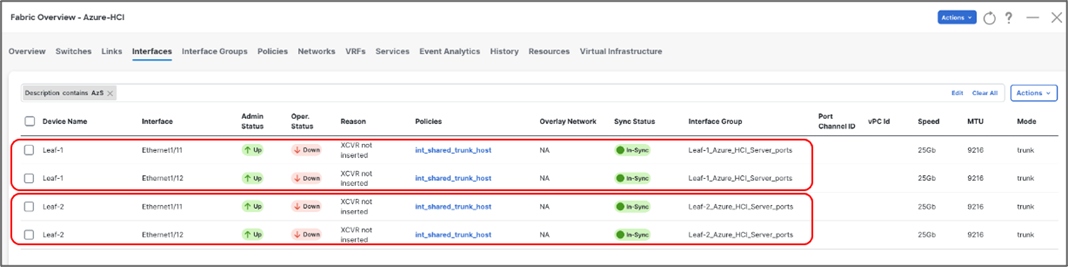
Now we have enabled PFC and applied QoS and Queuing policies on Leaf-1 & Leaf-2 respective interfaces. We’ll now create the networks (Vlans) required for Azure Stack HCI in next section.
Cisco NDFC enables the LLDP feature on all the devices in the VXLAN fabric and LLDP is enabled on all the interfaces on all devices. However, LLDP is not enabled by Cisco NDFC for traditional classic LAN fabrics. For traditional classic LAN fabrics, the _lldp policy feature must be associated to the Leaf switches for LLDP support.
Configure Networks for Azure Stack HCI
Following are the network requirements for Azure Stack HCI:
● Two Layer-3 networks with Anycast Gateway configured on the leafs
● Two Layer-2 networks for Storage (one for each leaf)
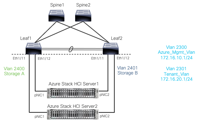
Cisco NX-OS based networks for Azure Stack HCI
On VXLAN fabric all the Layer-3 networks need to be mapped to a VRF which provides isolation between any two tenants. All the networks pertaining to a tenant are mapped to the respective tenant VRF. Layer-2 networks do not need to be mapped to VRF.
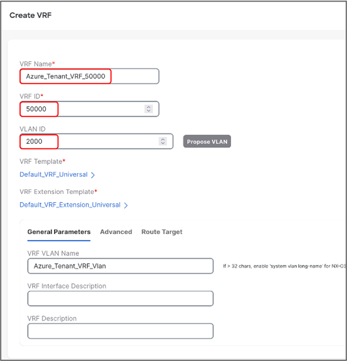
To create VRF, go to Fabric Detailed View > VRF > Actions and choose Create VRF and provide following parameters:
● VRF Name: Azure_Tenant_VRF_50000
● VRF ID: provide VNI for VRF
● VLAN ID: provide Vlan for VRF
● VRF VLAN Name: provide name for the VLAN (optional)
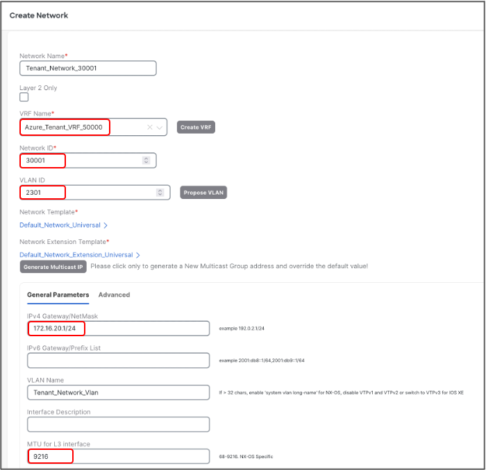
Once the VRF is created, Networks can be created. To create Networks, go to Fabric Detailed View >> Network >> Actions and choose Create Network.
Let’s create Layer-3 network used for management of Azure HCI Stack recourses with following parameters:
● Network Name – Azure_Mgmt_Network_30000
● VRF Name – provide Azure_Tenant_VRF_50000
● Network ID – 30000
● VLAN ID - 2300
● IPv4 Gateway/Netmask - 172.16.10.1/24
● VLAN Name – Azure_Mgmt Vlan
● MTU for L3 Interface - 9216 bytes

Let’s create second Layer-3 network used for Azure HCI Stack Tenants:
● Network Name: Tenant_Network_30001
● VRF Name: Azure_Tenant_VRF_50000
● Network ID: 30001
● VLAN ID: 2301
● IPv4 Gateway/Netmask: 172.16.20.1/24
● VLAN Name: Tenant_Network_Vlan
● MTU for L3 Interface: 9216 bytes
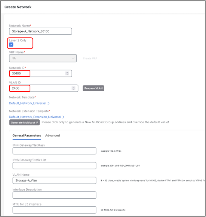
Now, we will create Layer-2 networks for Storage. Unlike the L3 networks, L2 networks don’t have any SVI and does not require mapping to VRF. To create L2 network, check Layer 2 Only check box.
Create L2 network for Storage-A with the following parameters:
● Network Name: Storage-A_30100
● Network ID: 30100
● VLAN ID: 2400
● VLAN Name: Storage-A_Vlan
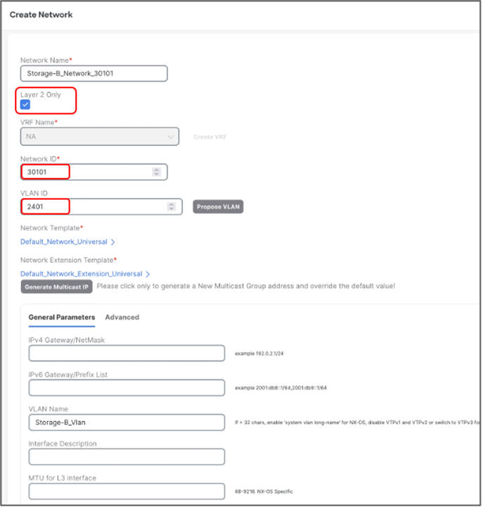
Create L2 network for Storage-B with the following parameters:
● Network Name – Storage-B_30101
● Network ID – 30101
● VLAN ID - 2401
● VLAN Name – Storage-B_Vlan
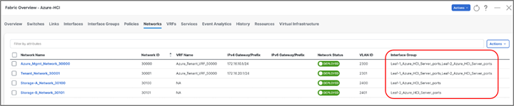
We can verify all the networks from Networks tab of the fabric -
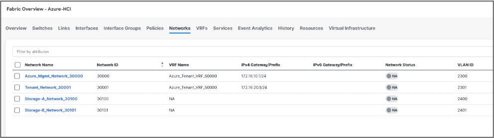
Next, we attach the networks to the interfaces, select the networks to be attached and click Actions >> Attach to Interface Group. We have attached Azure_Mgmt and Tenant networks to both the Leafs however Storage networks are attached to the respective switches.
Once all the networks are attached, select the networks and click on Actions > Deploy for NDFC to generate and push the config to the devices.
Build External Connectivity for Azure Stack HCI servers
Any network outside of VXLAN fabric is referred as external, to provide connectivity to such networks VRF_Lite (MPLS Option A) is used. Cisco NDFC supports full automation for extending connectivity to external networks from a VXLAN or Traditional Classical LAN fabric.
VXLAN devices which perform IPv4/IPv6 handoff are referred as Border devices this role is also supported in Cisco NDFC. Once the Tenant VRF is deployed on the border devices it can be further extended towards external networks.
Following NDFC settings are required under Resources tab of the fabric template for setting up external connectivity for VXLAN fabric.

Change VRF Lite IP Subnet range and subnet mask (if required), if required.
Before you start make sure, border devices have the VRF deployed. If not, attach the VRF to the border devices.
To configure the VRF_Lite extension, select the required VRF and go to the VRF detailed view from VXLAN fabric. Under VRF Attachments tab, select the border devices and click on Edit from Actions drop-down -
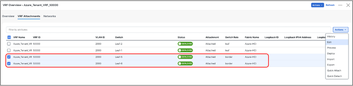
For each border device select VRF_LITE from drop-down under Extend and click on Attach-All button. Additional parameters can be provided by clicking on Exit link under Action.

Repeat the same steps and any additional border devices and click on Save.
Now we are back to VRF Attachment tab, to deploy the configuration to devices click on Deploy from Actions (at top) drop-down.
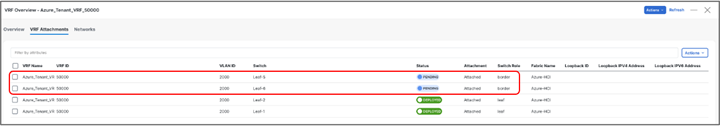
Cisco NDFC will push the required configuration to the border devices in the VXLAN fabrics.
If the external network is also managed by NDFC, perform Recalculate and Deploy in External fabric too for Cisco NDFC to push configuration to the device which is being used as other end for VRF_Lite extension.
This allows VXLAN networks to be advertised to external and vice-versa for any outside communication to take place.
| Revision |
Coverage |
| Initial version |
● Microsoft Azure Stack HCI 22H2
● Cisco ACI Release 6.0(3e)
● Cisco NX-OS Release 12.1.3b
|