Cisco UCS C240 M6 Solution for Microsoft Azure Stack HCI
Available Languages
Bias-Free Language
The documentation set for this product strives to use bias-free language. For the purposes of this documentation set, bias-free is defined as language that does not imply discrimination based on age, disability, gender, racial identity, ethnic identity, sexual orientation, socioeconomic status, and intersectionality. Exceptions may be present in the documentation due to language that is hardcoded in the user interfaces of the product software, language used based on RFP documentation, or language that is used by a referenced third-party product. Learn more about how Cisco is using Inclusive Language.
- US/Canada 800-553-2447
- Worldwide Support Phone Numbers
- All Tools
 Feedback
 Feedback
Published: March 2023

| Date |
Change |
| March 30, 2023 |
Original publication |
About the Cisco Validated Design Program
The Cisco Validated Design (CVD) program consists of systems and solutions designed, tested, and documented to facilitate faster, more reliable, and more predictable customer deployments. For more information, go to: http://www.cisco.com/go/designzone.
Cisco Validated Designs (CVDs) include systems and solutions that are designed, tested, and documented to facilitate and improve customer deployments. These designs incorporate a wide range of technologies and products into a portfolio of solutions that have been developed to address the business needs of customers. Cisco UCS Solution for Microsoft Azure HCI offers highly available and scalable software-defined hyperconverged solution that is enable by the purpose-built Azure Stack HCI 22H2 Operating System. The Azure Stack HCI 22H2 Operating System is an Azure hybrid cloud designed hyperconverged solution that is based on Microsoft Windows Server 2022 and includes Storage Spaces Direct, Windows Failover Clustering, and Hyper-V.
Azure Stack is a family of three solutions that include Azure Stack HCI, Azure Stack Hub, and Azure Stack Edge. Azure Stack HCI is focused on the following use cases:
● Datacenter consolidation
● Virtual desktop Infrastructure
● Business critical infrastructure
● Storage cost reduction
● High availability and disaster recovery
● Enterprise application virtualization
● Azure Kubernetes Services
● Remote branch office system
● Arc enabled services
This document describes the architecture, topology, and deployment of Azure Stack HCI on Cisco UCS C240 M6SN with Cisco Nexus 9300 series switches. Following the deployment guidance as specified in this document will result in a solution that adheres to both Cisco and Microsoft best practices.
This chapter contains the following:
● Audience
Software defined data center solutions enable IT organizations to optimize resource efficiency and improve service delivery. It combines compute virtualization, software defined storage, and virtualized networking that meets or exceeds high availability, performance, and security requirements of the most demanding deployments. The solution uses a shared-nothing architecture and takes advantage of the compute, storage, and network resources that are available within individual server. The servers are connected with external switching fabric that is provides reliable high throughput and low latency.
The audience of this document includes, but is not limited to, sales engineers, field consultants, professional services, IT managers, partner engineers, and customers who want to take advantage of an infrastructure that is built to deliver IT efficiency and enable IT innovation.
This overview and step-by-step deployment document is intended to describe in detail the procedure used to deploy the Azure Stack HCI solution on a Cisco UCS C240 M6SN rack server with the Mellanox ConnectX-6 DX NIC and connected to Cisco Nexus 9300 series switches. The procedure in this document should be used for deploying and evaluating this solution in a lab environment prior to deploying the solution in production. The deployment details described in this document need to be implemented as described unless stated otherwise.
This document will be periodically updated with new content. The contents will include procedures for deploying additional capabilities as well as qualified Cisco UCS firmware and drivers that must be used for deploying this solution.
This chapter contains the following:
● Cisco UCS C240 M6 Rack Server
● NVIDIA/Mellanox ConnectX-6 DX Ethernet SmartNIC
● Cisco Integrated Management Controller (IMC)
The Cisco UCS C240 M6 Rack Servers is a 2-socket, 2-Rack-Unit (2RU) rack server offering industry-leading performance and expandability. It supports a wide range of storage and I/O-intensive infrastructure workloads, from big data and analytics to collaboration. Cisco UCS C-Series Rack Servers can be deployed as standalone servers or as part of a Cisco Unified Computing System (Cisco UCS) managed environment to take advantage of Cisco’s standards-based unified computing innovations that help reduce customers’ Total Cost of Ownership (TCO) and increase their business agility.
In response to ever-increasing computing and data-intensive real-time workloads, the enterprise-class Cisco UCS C240 M6 server extends the capabilities of the Cisco UCS portfolio in a 2RU form factor. It incorporates the 3rd Generation Intel Xeon Scalable processors, supporting up to 40 cores per socket and 33 percent more memory versus the previous generation.
The Cisco UCS C240 M6 rack server brings many new innovations to the UCS rack server portfolio. With the introduction of PCIe Gen 4.0 expansion slots for high-speed I/O, DDR4 memory bus, and expanded storage capabilities, the server delivers significant performance and efficiency gains that will improve your application performance. Its features including the following:
● Supports the third-generation Intel Xeon Scalable CPUs, with up to 40 cores per socket
● Up to 32 DDR4 DIMMs for improved performance including higher density DDR4 DIMMs (16 DIMMs per socket)
● 16x DDR4 DIMMs + 16x Intel Optane persistent memory modules for up to 12 TB of memory
● Up to 8 PCIe Gen 4.0 expansion slots plus a modular LAN-on-motherboard (mLOM) slot
● Support for Cisco UCS VIC 1400 Series adapters as well as third-party options
● Up to 28 hot-swappable Small-Form-Factor (SFF) SAS/SATA/NVMe:
◦ 28 SFF SAS/SATA (with up to 8x NVMe)
◦ 26 NVMe in all NVMe SKU (SN)
◦ 14 NVMe in all NVMe SKU (N)
◦ 16 LFF drives with options 4 rear SAS/SATA/NVMe) disk drives, or 16 Large-Form-Factor (LFF) 3.5-inch drives plus 2 rear hot-swappable SFF drives
◦ Support for a 12-Gbps SAS modular RAID controller in a dedicated slot, leaving the remaining PCIe Gen 4.0 expansion slots available for other expansion cards
◦ Option for 26 NVMe drives at PCIe Gen4 x4 (2:1 oversubscribed)
● M.2 boot options
◦ Up to 960 GB with optional hardware RAID
● Up to five GPUs supported
● Modular LAN-on-motherboard (mLOM) slot that can be used to install a Cisco UCS Virtual Interface Card (VIC) without consuming a PCIe slot, supporting quad port 10/40 Gbps or dual port 40/100 Gbps network connectivity
● Dual embedded Intel x550 10GBASE-T LAN-on-motherboard (LOM) ports
● Modular M.2 SATA SSDs for boot
Table 1. Item and Specification Details
| Item |
Specifications |
| Form factor |
2RU rack server |
| Processors |
3rd Generation Intel Xeon Scalable processors (1 or 2) |
| Memory |
32 DDR4 DIMM slots: 16, 32, 64, 128 and 256 GB and up to 3200 MHz Support for the Intel Optane DC Persistent Memory (128G, 256G, 512G) |
| PCIe expansion |
8 PCIe 4.0 slots plus 1 dedicated 12-Gbps RAID controller slot and 1 dedicated mLOM slot |
| Storage controller |
Internal controllers: Cisco 12-Gbps Modular SAS Host Bus Adapter (HBA) |
| Internal storage |
Backplane options:
● Up to 28 x 2.5-inch SAS and SATA HDDs and SSDs (up to 4 NVMe PCIe drives)
● Up to 26 x 2.5-inch NVMe PCIe SSDs (All direct attach Gen4 x4)
● Up to 16 x 3.5-inch SAS and SATA HDDs and SSDs, and optional 2 rear 2.5-inch HDDs and SSDs (up to 4 NVMe PCIe drives)
|
| Embedded Network Interface Cards (NICs) |
Dual 10GBASE-T Intel x550 Ethernet ports |
| mLOM |
Dedicated mLOM slot that can flexibly accommodate 1-, 10-, 25-, 40-, and 100-Gbps adapters |
| Power supplies |
Hot-pluggable, redundant 1050W AC, 1050W DC, 1600W AC and 2300W AC |
| Other storage |
Dedicated Baseboard Management Controller (BMC) FlexMMC for utilities (on board) Dual M.2 SATA SSDs with HW Raid support |
| Management |
|
| Rack options |
Cisco ball-bearing rail kit with optional reversible cable management farm |
| Hardware and software interoperability |
See the Cisco Hardware and Software Interoperability List for a complete listing of supported operating systems and peripheral options. |
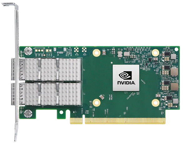
NVIDIA/Mellanox ConnectX-6 DX Ethernet SmartNIC
NVIDIA ConnectX-6 Dx is a highly secure and advanced smart network interface card (SmartNIC) that accelerates mission-critical cloud and data center applications, including security, virtualization, SDN/NFV, big data, machine learning, and storage. ConnectX-6 Dx provides up to two ports of 100Gb/s or a single port of 200Gb/s Ethernet connectivity and is powered by 50Gb/s (PAM4) or 25/10 Gb/s (NRZ) SerDes technology.
ConnectX-6 Dx features virtual switch (vSwitch) and virtual router (vRouter) hardware accelerations delivering orders-of-magnitude higher performance than software-based solutions. ConnectX-6 Dx supports a choice of single-root I/O virtualization
(SR-IOV) and VirtIO in hardware, enabling customers to best address their application needs. By offloading cloud networking workloads, ConnectX-6 Dx frees up CPU cores for business applications while reducing total cost-of-ownership.
In an era where data privacy is key, ConnectX-6 Dx provides built-in inline encryption/decryption, stateful packet filtering, and other capabilities, bringing advanced security down to every node with unprecedented performance and scalability.
Built on the solid foundation of NVIDIA’s ConnectX line of SmartNICs, ConnectX-6 Dx offers best-in-class RDMA over Converged Ethernet (RoCE) capabilities, enabling scalable, resilient, and easy-to-deploy RoCE solutions. For data storage, ConnectX-6 Dx optimizes a suite of storage accelerations, bringing NVMe-oF target and initiator offloads.
Figure 1. NVDIA/Mellanox ConnectX-6 DX
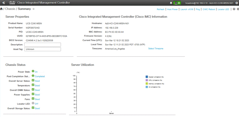
Cisco Integrated Management Controller (IMC)
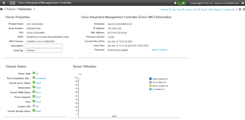
The Cisco Integrated Management Controller (IMC) is a baseboard management controller that provides embedded server management for Cisco UCS C-Series Rack Servers and Cisco UCS S-Series Storage Servers. The Cisco IMC enables system management in the data center and across distributed branch-office locations. It supports multiple management interfaces, including a Web User Interface (Web UI), a Command-Line Interface (CLI), and an XML API that is consistent with the one used by Cisco UCS Manager. IMC also supports industry-standard management protocols, including Redfish, Simple Network Management Protocol Version 3 (SNMPv3), and Intelligent Platform Management Interface Version 2.0 (IPMIv2.0). The figure below shows a sample Cisco IMC screen.
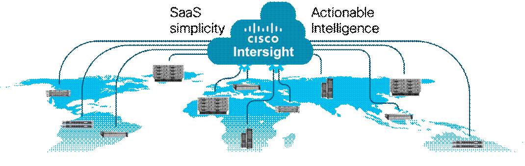
Cisco Intersight
Cisco Intersight is Cisco’s systems management platform that delivers intuitive computing through cloud-powered intelligence. This platform offers a more intelligent level of management that enables IT organizations to analyze, simplify, and automate their environments in ways that were not possible with prior generations of tools. This capability empowers organizations to achieve significant savings in Total Cost of Ownership (TCO) and to deliver applications faster in support of new business initiatives. The advantages of the model-based management of the Cisco UCS platform plus Cisco Intersight are extended to Cisco UCS servers and Cisco HyperFlex, including Cisco HyperFlex Edge systems. Cisco HyperFlex Edge is optimized for remote sites, branch offices, and edge environments.
Endpoints supported by Cisco Intersight use model-based management to provision servers and associated storage and fabric automatically, regardless of form factor. Cisco Intersight works in conjunction with Cisco UCS Manager and the Cisco Integrated Management Controller (IMC). By simply associating a model-based configuration with a resource through server profiles, your IT staff can consistently align policy, server personality, and workloads. These policies can be created once and used by IT staff with minimal effort to deploy servers. The result is improved productivity and compliance and lower risk of failures due to inconsistent configuration.
Cisco Intersight will be integrated with data-center and hybrid-cloud platforms and services to securely deploy and manage infrastructure resources across data-center and edge environments. In addition, Cisco provides integrations to third-party operations tools, starting with ServiceNow, to allow customers to use their existing solutions more effectively.
Cisco Intersight offers flexible deployment either as Software as a Service (SaaS) on Intersight.com or running on your premises with the Cisco Intersight virtual appliance. The virtual appliance provides users with the benefits of Cisco Intersight while allowing more flexibility for those with additional data locality and security requirements.
Cisco Intersight Features and Benefits
Table 2 lists the main features and benefits of Cisco Intersight.
Table 2. Cisco Intersight Features and Benefits
| Feature |
Benefit |
| Unified management |
Simplify Cisco UCS, Cisco HyperFlex, Pure Storage, and Cisco Network Insights management from a single management platform. Increase scale across data centers and remote locations without additional complexity. Use a single dashboard to monitor Cisco UCS and Cisco HyperFlex systems. Cisco UCS Manager, Cisco IMC software, Cisco HyperFlex Connect, and Cisco UCS Director tunneling allow access to element managers that do not have local network access. |
| Configuration, provisioning, and server profiles |
Treat Cisco UCS servers and storage as infrastructure resources that can be allocated and reallocated among application workloads for more dynamic and efficient use of server capacity. Create multiple server profiles with just a few clicks or through the available API, automating the provisioning process. Clone profiles to quickly provision Cisco UCS C-Series Rack Servers in standalone mode. Create, deploy, and manage your Cisco HyperFlex configurations. Help ensure consistency and eliminate configuration drift, maintaining standardization across many systems. |
| Inventory information and status |
Display and report inventory information for Cisco UCS and Cisco HyperFlex systems. Use global search to rapidly identify systems based on names, identifiers, and other information. Use tagging to associate custom attributes with systems. Monitor Cisco UCS and Cisco HyperFlex server alerts and health status across data centers and remote locations. View your Cisco HyperFlex configurations. Track and manage firmware versions across all connected Cisco UCS and Cisco HyperFlex systems. Track and manage software versions and automated patch updates for all claimed Cisco UCS Director software installations. |
| Enhanced support experience |
Get centralized alerts about failure notifications. Automate the generation, forwarding, and analysis of technical support files to the Cisco Technical Assistance Center (TAC) to accelerate the troubleshooting process. |
| Open API |
A RESTful API that supports the OpenAPI Specification (OAS) to provide full programmability and deep integrations systems. The Python and PowerShell SDKs will enable integrations with Ansible, Chef, Puppet, and other DevOps and IT Operations Management (ITOM) tools. ServiceNow integration to provide inventory and alerts to the IT Service Management platform. |
| Seamless integration and upgrades |
Upgrades are available for Cisco UCS, Cisco HyperFlex systems, and Cisco UCS Director software running supported firmware and software versions. Upgrades to Cisco Intersight are delivered automatically without requiring the resources of traditional management tool upgrades and disruption to your operations. |
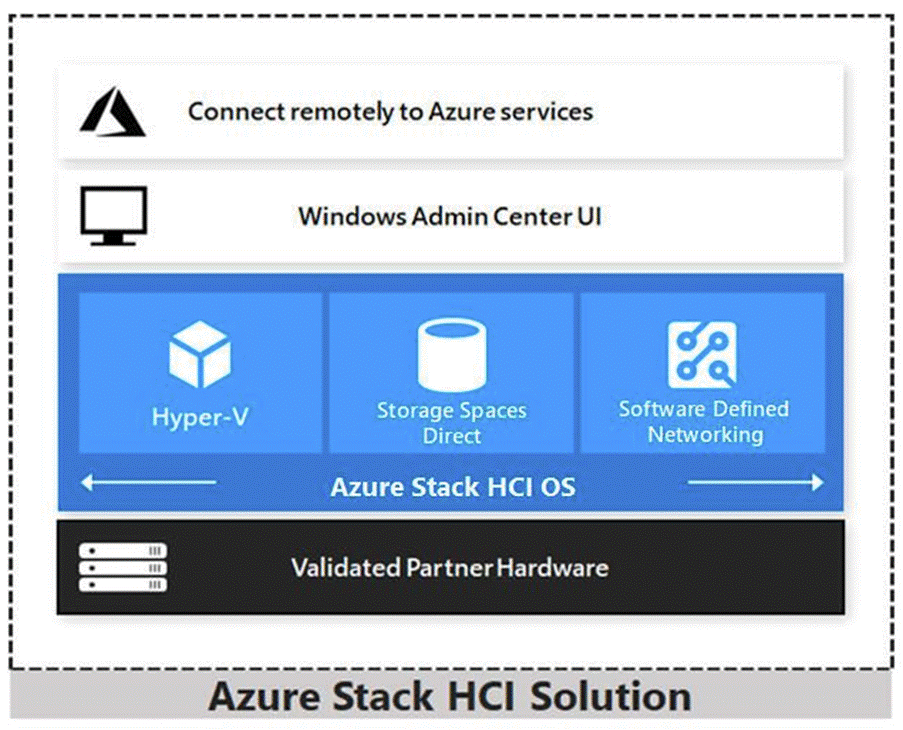
Azure Stack HCI 22H2 is a hyper-converged Windows Server 2022 cluster that uses validated hardware to run virtualized workloads on-premises. You can also optionally connect to Azure services for cloud-based backup, site-recovery, and more. Azure Stack HCI solutions use Microsoft-validated hardware to ensure optimal performance and reliability, and include support for technologies such as NVMe drives, persistent memory, and remote-direct memory access (RDMA) networking.
Azure Stack HCI is a solution that combines several products:
● Hardware from an OEM partner
● Azure Stack HCI OS 22H2
● Windows Admin Center
● Azure services (optional)
Azure Stack HCI is Microsoft’s hyperconverged solution available from a wide range of hardware partners. Consider the following scenarios for a hyperconverged solution to help you determine if Azure Stack HCI is the solution that best suits your needs:
● Refresh aging hardware. Replace older servers and storage infrastructure and run Windows and Linux virtual machines on-premises and at the edge with existing IT skills and tools.
● Consolidate virtualized workloads. Consolidate legacy apps on an efficient, hyperconverged infrastructure. Tap into the same types of cloud efficiencies used to run hyper-scale datacenters such as Microsoft Azure.
● Connect to Azure for hybrid cloud services. Streamline access to cloud management and security services in Azure, including offsite backup, site recovery, cloud-based monitoring, and more.
Hyperconverged Efficiencies
Azure Stack HCI solutions bring together highly virtualized compute, storage, and networking on industry-standard x86 servers and components. Combining resources in the same cluster makes it easier for you to deploy, manage, and scale. Manage with your choice of command-line automation or Windows Admin Center.
Achieve industry-leading virtual machine performance for your server applications with Hyper-V, the foundational hypervisor technology of the Microsoft cloud, and Storage Spaces Direct technology with built-in support for NVMe, persistent memory, and remote-direct memory access (RDMA) networking.
It helps keep apps and data secure with shielded virtual machines, network micro segmentation, and native encryption.
Hybrid Cloud Capabilities
You can take advantage of cloud and on-premises working together with a hyperconverged infrastructure platform in public cloud. Your team can start building cloud skills with built-in integration to Azure infrastructure management services:
● Azure Site Recovery for high availability and disaster recovery as a service (DRaaS).
● Azure Monitor, a centralized hub to track what’s happening across your applications, network, and infrastructure – with advanced analytics powered by AI.
● Cloud Witness, to use Azure as the lightweight tie breaker for cluster quorum.
● Azure Backup for offsite data protection and to protect against ransomware.
● Azure Update Management for update assessment and update deployments for Windows VMs running in Azure and on-premises.
● Azure Network Adapter to connect resources on-premises with your VMs in Azure via a point-to-site VPN.
● Sync your file server with the cloud, using Azure File Sync.
Management Tools
Azure Stack HCI uses the same virtualization and software-defined storage and networking software as Azure Stack Hub. However, with Azure Stack HCI you have full admin rights on the cluster and can manage any of its technologies directly:
● Hyper-V
To manage these technologies, you can use the following management tools:
● Windows Admin Center (optional)
● System Center (Optional)
● Other management tools such as Server Manager, and MMC snap-ins (Optional)
● Non-Microsoft tools such as 5Nine Manager (Optional)
If you choose to use System Center to deploy and manage your infrastructure, you'll use System Center Virtual Machine Management (VMM) and System Center Operations Manager. With VMM, you provision and manage the resources needed to create and deploy virtual machines and services to private clouds.
Hyper-V
Hyper-V is Microsoft's hardware virtualization product. It lets you create and run a software version of a computer, called a virtual machine. Each virtual machine acts like a complete computer, running an operating system and programs. When you need computing resources, virtual machines give you more flexibility, help save time and money, and are a more efficient way to use hardware than just running one operating system on physical hardware.
Hyper-V runs each virtual machine in its own isolated space, which means you can run more than one virtual machine on the same hardware at the same time. You might want to do this to avoid problems such as a crash affecting the other workloads, or to give different people, groups, or services access to different systems.
Storage Spaces Direct
Storage Spaces Direct uses industry-standard servers with local-attached drives to create highly available, highly scalable software-defined storage at a fraction of the cost of traditional SAN or NAS arrays. The hyper-converged architecture radically simplifies procurement and deployment, while features such as caching, storage tiers, and erasure coding, together with the latest hardware innovations such as RDMA networking and NVMe drives, deliver unrivaled efficiency and performance.
One cluster for compute and storage. The hyper-converged deployment option runs Hyper-V virtual machines directly on the servers providing the storage, storing their files on the local volumes. This eliminates the need to configure file server access and permissions and reduces hardware costs for small-to-medium business or remote office/branch office deployments.
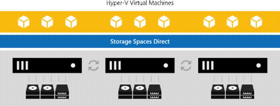
Storage Spaces Direct is the evolution of Storage Spaces, first introduced in Windows Server 2012. It leverages many of the features you know today in Windows Server, such as Failover Clustering, the Cluster Shared Volume (CSV) file system, Server Message Block (SMB) 3, and of course Storage Spaces. It also introduces new technology, most notably the Software Storage Bus.
Figure 2. Overview of the Storage Spaces Direct Stack
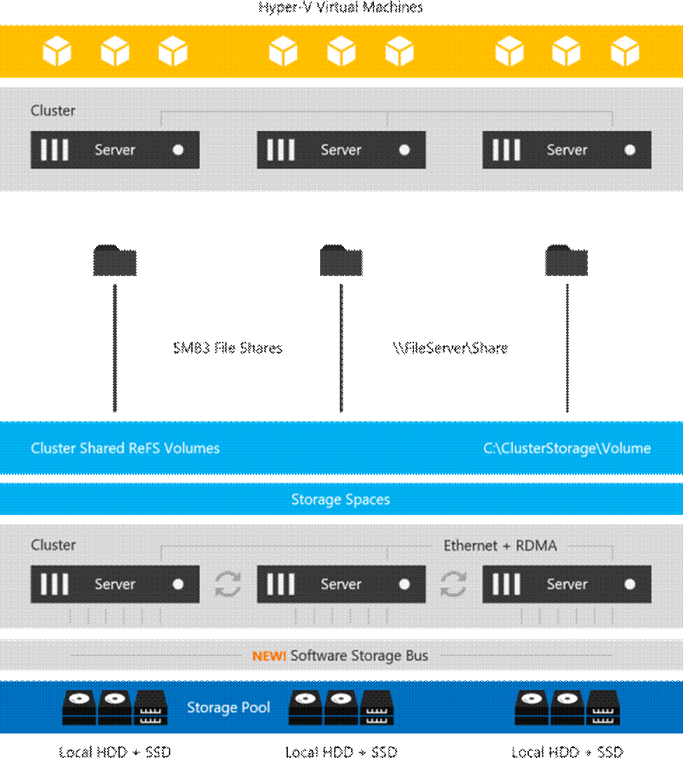
Networking Hardware. Storage Spaces Direct uses SMB3, including SMB Direct and SMB Multichannel, over Ethernet to communicate between servers. Microsoft strongly recommends 10+ GbE with remote-direct memory access (RDMA).
Storage Hardware. From 1 to 16 servers with local-attached SATA, SAS, or NVMe drives. Each server must have at least 2 solid-state drives, and at least 4 additional drives. The SATA and SAS devices should be behind a host-bus adapter (HBA) and SAS expander. We strongly recommend the meticulously engineered and extensively validated platforms from our partners (coming soon).
Failover Clustering. The built-in clustering feature of Windows Server is used to connect the servers.
Software Storage Bus. The Software Storage Bus is new in Storage Spaces Direct. It spans the cluster and establishes a software-defined storage fabric whereby all the servers can see all of each other's local drives. You can think of it as replacing costly and restrictive Fibre Channel or Shared SAS cabling.
Storage Bus Layer Cache. The Software Storage Bus dynamically binds the fastest drives present (e.g. SSD) to slower drives (e.g. HDDs) to provide server-side read/write caching that accelerates IO and boosts throughput.
Storage Pool. The collection of drives that form the basis of Storage Spaces is called the storage pool. It is automatically created, and all eligible drives are automatically discovered and added to it. We strongly recommend you use one pool per cluster, with the default settings. Read our Deep Dive into the Storage Pool to learn more.
Storage Spaces. Storage Spaces provides fault tolerance to virtual "disks" using mirroring, erasure coding, or both. You can think of it as distributed, software-defined RAID using the drives in the pool. In Storage Spaces Direct, these virtual disks typically have resiliency to two simultaneous drive or server failures (e.g. 3-way mirroring, with each data copy in a different server) though chassis and rack fault tolerance is also available.
Resilient File System (ReFS). ReFS is the premier filesystem purpose-built for virtualization. It includes dramatic accelerations for .vhdx file operations such as creation, expansion, and checkpoint merging, and built-in checksums to detect and correct bit errors. It also introduces real-time tiers that rotate data between so-called "hot" and "cold" storage tiers in real-time based on usage.
Cluster Shared Volumes. The CSV file system unifies all the ReFS volumes into a single namespace accessible through any server, so that to each server, every volume looks and acts like it's mounted locally.
Failover Clustering
A failover cluster is a group of independent computers that work together to increase the availability and scalability of clustered roles (formerly called clustered applications and services). The clustered servers (called nodes) are connected by physical cables and by software. If one or more of the cluster nodes fail, other nodes begin to provide service (a process known as failover). In addition, the clustered roles are proactively monitored to verify that they are working properly. If they are not working, they are restarted or moved to another node.
Failover clusters also provide Cluster Shared Volume (CSV) functionality that provides a consistent, distributed namespace that clustered roles can use to access shared storage from all nodes. With the Failover Clustering feature, users experience a minimum of disruptions in service.
Failover Clustering has many practical applications, including:
● Highly available or continuously available file share storage for applications such as Microsoft SQL Server and Hyper-V virtual machines
● Highly available clustered roles that run on physical servers or on virtual machines that are installed on servers running Hyper-V
This chapter contains the following:
The Cisco solution for Azure Stack HCI architecture must be implemented as described in this document. Cisco provides a specific PID for ordering the configuration. The PID includes all of the required components that comprise the solution. The Azure Stack HCI cluster can be scaled from 1 to 16 servers. The architecture for the deployment of Azure Stack HCI solution consists of a storage switched configuration using two TOR switches with fully converged host network adapters.
The architecture has a data fabric and a management fabric. The servers connect to the data fabric using dual 100Gb connections. This data fabric is provided by the Cisco 9300 series switches which provide layer 2 connectivity and carries all the Azure Stack HCI network traffic (management, compute, and RDMA storage traffic). Server management is facilitated through an Out-of-band (OOB) management network that connects the server’s dedicated management port to an OOB management switch with 1GbE links. The servers Azure Stack HCI OS 22H2 provides a rich set of software defined services that are core to this solution.
The data center is expected to have infrastructure services such as DNS and Active Directory. WDS (Windows Deployment Service) and DHCP are also recommended to expedite deployments. These services must be accessible through the ToR (Top of Rack) or EoR (End of Row) network switches that connect the Cisco UCS C240 M6 Servers that are part of the Cisco solution for Azure Stack HCI to the datacenter infrastructure.
Azure Stack HCI Components
Cisco UCS C240 M6SN Servers
The Cisco UCS 240 M6SN server configuration consists of a dual-port 100GbE NVDIA ConnectX-6 DX network interface card, teamed with each port connecting to different ToR switches and a single 1GbE dedicated management port which connects to an OOB management switch for communication with the Cisco Integrated Management Controller in each server.
The ToR switches, in this case Cisco Nexus 9300 series switches, carry both Azure Stack HCI cluster traffic and management network traffic to the Cisco UCS C240 M6SN servers. The Azure Stack HCI cluster traffic flows throw 100GbE links to the NVIDIA ConnectX-6 DX network interface card in each server. Out of band management traffic is facilitated by a 1GbE connection to each of the UCS C240 M6SN severs.
The ToR (Top of Rack) switches can be any Cisco Nexus switches that have confirmed support for the Azure Stack HCI requirements. The list of supported Cisco Nexus series switches and the NX-OS version can be viewed here. The ToR switch provides layer 2 and layer 3 connectivity to the Azure Stack HCI cluster nodes. The ToR switches should include a security focused configuration that is standardized within the datacenter network. Two ToR switches in Virtual Port Channel (VPC) configuration provide high availability and redundancy for the network traffics.
The Appendix of this document has sample configurations that can be implemented in the ToR switch. These sample configurations include vPC, SVI, HSRP, and DHCP Relay.
It is expected that the datacenter has a secure OoB (Out of Band) management network that is used to managed network devices in the datacenter. Cisco UCS C240 M6SN servers and the ToR switches are directly connected to the out of band management switches and a disjoint layer-2 configuration is used to keep the management network path separate from the data network path. The OoB network needs to have internet access in order for Cisco Intersight to be able to access the UCS C240 M6 servers.
The logical topology is comprised of the following:
● Tenant Network
The Tenant network is a VLAN trunk that carries one or more VLANs that provide access to the tenant virtual machines. Each VLAN is provisioned in the ToR switch and SET switch running on the physical server. Each tenant VLAN is expected have an IP subnet assigned to it.
● Management Network
The management network is a VLAN that carries network traffic to the parent partition. This network is used to access the host operating system. The connectivity to the management network is provided by the management (Mgmt) vNIC in the parent partition. Fault tolerance for the management vNIC is provided by the SET switch. A bandwidth limit can be assigned to the management, as necessary.
● Storage Network
The storage network carries RoCEv2 RDMA network traffic that is used for Storage Spaces Direct, storage replication, and Live Migration network traffic. This network is also used for cluster management communication. The storage network has a Storage A and Storage B segment, each with its own IP subnet. This design keeps the east-west RDMA isolated to the ToR switches and avoids the need for the upstream switches to be configured for supporting RoCEv2 traffic.
Figure 4 illustrates the east-west RDMA traffic isolation.
Figure 4. East-West RDMA Traffic Isolation
● SET Switch
This is a virtual switch with embedded teaming capabilities. The SET Switch provides teaming capabilities for network traffic that does not use SMB-Multichannel. SMB Direct (RDMA) traffic uses SMB-Multichannel for link aggregation and redundancy instead of the teaming feature in the SET switch.
MAC addresses for virtual NICs are randomly assigned to one on the physical NIC ports on the host. This MAC address assignment can be moved from one physical NIC to another at any time by the SET switch. This behavior provides load balancing and fault tolerance. A consequence of this behavior is that some of the east-west network traffic that is not storage SMB Direct (RDMA) traffic will transverse the upstream router/switch. An example of this is when virtual machine A with a virtual NIC MAC address assigned to physical NIC A communicates with virtual machine B that has virtual NIC MAC assigned to physical NIC B. Figure 5 illustrates this behavior.
Figure 5. MAX Address Assignment
● Guest Partition
The tenant virtual machines run in the guest partition on the Hyper-V host. Each virtual machine runs in isolation from others and does not have direct access to physical hardware in the host. Network connectivity is provided to the tenant virtual machine by connecting synthetic NIC in the virtual machine to the SET switch on the host.
● Parent Partition
The parent partition is the host operating system that runs the virtualization management stack and has access to the physical server hardware. The parent partition has one management vNIC and two storage vNICs. An optional dedicated vNIC for backup operations can be added as needed.
Deployment Hardware and Software
This chapter contains the following:
● Customer Support Requirements
Firmware and drivers can be found on the Cisco download portal for Windows Server 2022 (Azure Stack HCI 22H2). These components will be periodically updated. Please sign up for notification at this download portal to receive notifications emails when updates are available.
The Cisco UCS C240 M6 standalone server platform for Microsoft Azure Stack HCI 22H2 firmware download portal can be accessed from the Cisco UCS C-Series Rack-Mount Standalone Server Software Download page. Also, it can be set up to notify you about the availability of the new firmware. Cisco highly recommends that you sign up for these notifications.
The following software components hosted on Cisco download portal are required for the firmware upgrade procedure:
| Component |
Description |
| ucs-c240m6-huu-4.2.3b.iso |
Cisco UCS C240 M6 Rack Server Software |
| ucs-cxxx-drivers-windows.4.2.3a.iso |
Azure Stack HCI 22H2 (Win 2022) drivers for UCS C240 M6SN servers |
The following tables list the individual component version that are part of the respective firmware bundles and driver package:
| Cisco UCS C-Series Rack-Mount Standalone Server |
||
| Component |
Firmware Version |
|
| Cisco UCS C-Series Rack-Mount Standalone Server Software |
4.2(3b) |
|
| ISO image of UCS-Rack related windows drivers only |
ucs-cxxx-drivers-windows.4.2.3a.iso |
|
| Cisco UCS C240 M6SN Servers |
|
||
| Component |
C-Series Rack-Mount |
Firmware Version |
Driver Version |
| BIOS |
4.2(3b) |
C240M6.4.2.3a.0.1029220536 |
|
| CIMC (BMC) |
4.2(3b) |
4.2.3b |
|
| Board Controller |
4.2(3b) |
63 |
|
| SAS HBA |
4.1(3h) |
11.00.05.02 |
2.61.19.80 (inbox) |
| Cisco-MLNX MCX623106AS-CDAT 2x100GbE QSFP56 PCIe |
4.2(3b) |
22.34.1002 |
3.0.25668.0 |
| MegaSR1 |
4.2(3b) |
|
18.03.2022.0802 |
| Boot SSD (UCS-M2-960GB) |
4.2(3b) |
D0MH077 |
10.0.17763.887 (inbox) |
| U.2 Intel P5500 NVMe |
4.2(3b) |
2CV1C033 |
10.0.20348.1607 (inbox) |
| Host Operating System |
|
| Host OS Version |
Azure Stack HCI OS 22H2 with current updates |
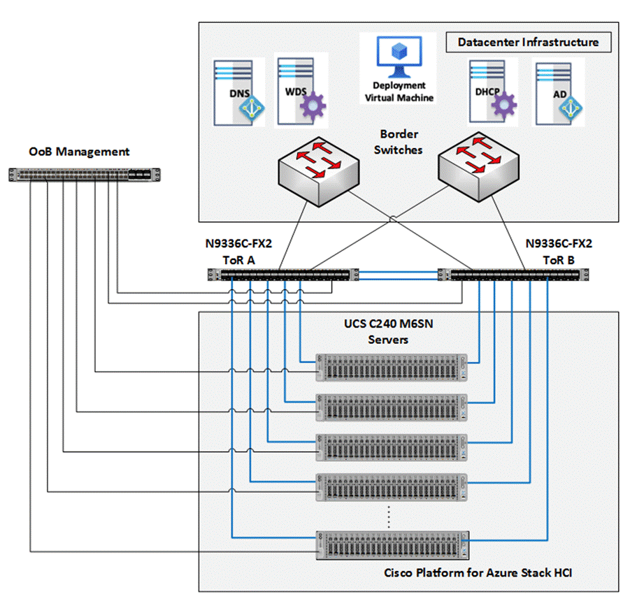
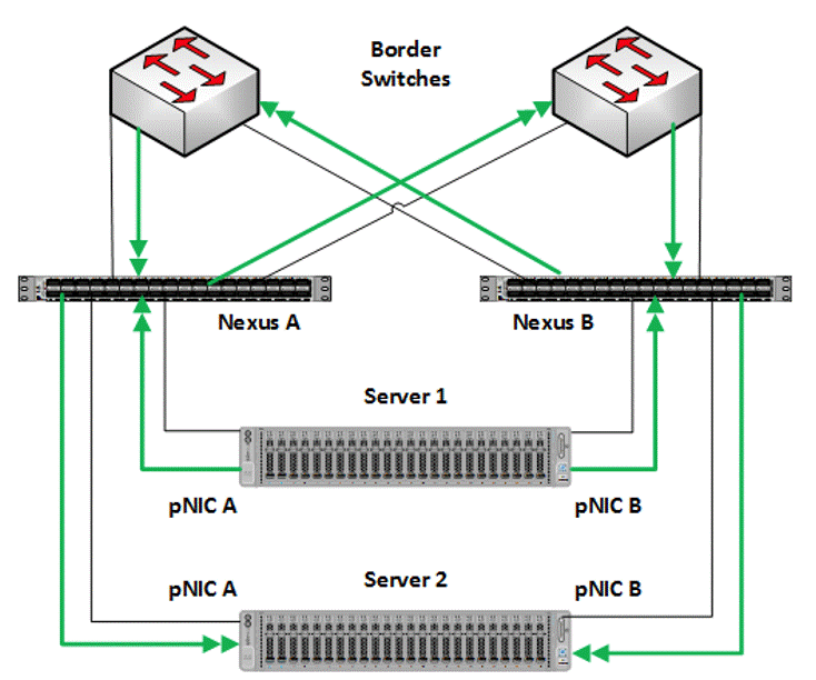
Figure 7 illustrates the physical topology of an Azure Stack HCI deployment on Cisco UCS C240 M6 servers with Cisco Nexus 9300 series switches. The cabling information can be found in the Appendix of this document.
Figure 7. Physical Infrastructure
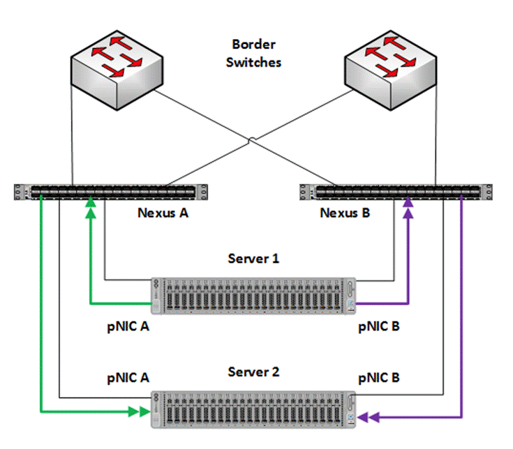
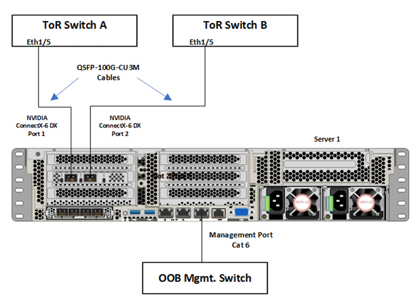
Figure 8 illustrates the data ports and management ports on the back of each server. In this example Server 1 has its two 100Gb data ports connected to ports eth1/5 port on ToR A and B switches. The single dedicated out-of-band management port is connected to an OOB management switch.
Figure 8. Data Ports and Management Ports
The following is the checklist for the deployment of a 4-node Azure Stack HCI cluster:
● ToR switch must support the Azure Stack HCI requirements
● ToR switch must implement L2 and L3 configuration for transporting northbound host and tenant traffic
● Out of Band management switch must be provided for connecting the ToR switches and Cisco UCS C240 M6 servers
● 3 IP addresses are required on the Out of Band Management Network for the ToR Cisco Nexus switches
● 1 IP address must be provided for each host (server) on the Out of Band Management Network
● VLANs
◦ 1 Management
◦ 2 Storage
◦ 1 or more tenant
● IP subnets and addresses for all endpoints for the above VLANs
● Storage VLANs and Storage subnets do not need to be configured on the ToR switches
● Host operating system must have access to Azure
● Datacenter infrastructure that includes Active Directory Services, DNS, and NTP
● Cluster Quorum Witness
◦ Can be Files Share or Cloud Witness
◦ Required for Cluster with fewer than 5 cluster nodes
● Recommended for clusters with 5 or greater n number of nodes
● Deployment host must be provided with access to the Out-of-Band Managed network and host management network
◦ See the Remote Management Host configuration in the Appendix
● Deployment host must be running Windows Server 2019 or Windows Server 2022 and be domain joined to the same domain as the Azure Stack HCI hosts
● Account used to deploy Azure Stack HCI must have administrative rights on the Azure stack hosts and permissions to join the domain, add cluster securing principle to the domain, update the DNS A records for the computer joining the domain and Cluster Aware Updating services, and store Bitlocker keys in the domain
● Azure Account for registering Azure Stack HCI
● Download Azure Stack HCI OS 22H2 from Microsoft download site
● Download Cisco Drivers for Azure Stack HCI 22H2 deployment from Cisco download portal (link to be added)
● Download Cisco UCS Manager configuration script for Azure Stack HCI 22H2 deployments from Cisco download portal (link to be added)
● Recommended Items
◦ Windows Deployment Service for PXE boot OS installation (Can be running on deployment host)
◦ DHCP server with scope for management subnet to support PXE booting. Scope is temporary and only needed during PXE boot installation phase. (Can be running on deployment host)
Bill of Materials
This solution must be purchased using the Cisco UCS product ID UCS-MAH-B00R00-M6. This product ID includes all of the required hardware to build the solution as well as the Cisco Solution Support for this solution. A sample BoM is documented in the Cisco UCS for Microsoft Azure Stack HCI Datasheet at the following link:
The solution must adhere to Cisco Guidance for deploying Azure Stack HCI on Cisco UCS product ID UCS-MAH-B00R00.
Firmware and driver version must match the versions specified in this document. This document will be update periodically with more current firmware and driver versions. Customers are required to update their systems to the latest recommended firmware and driver version for this Azure Stack HCI solution.
Note: The current firmware and drivers can be downloaded from the Cisco download portal for Azure Stack HCI. The link to the download portal is in the Firmware and Drivers section.
Note: You must obtain an Azure Stack HCI support contract from Microsoft. The following is an example of this type of support contract:
● Unified Support for Enterprise
● Premier Support for Enterprise
For support option details, go to: Get support for Azure Stack HCI - Azure Stack HCI | Microsoft Docs
This chapter contains the following:
● Configure Cisco Integrated Management Controller for Cisco UCS C240 Servers
● Claim Cisco UCS C240 Standalone Servers in Cisco Intersight
● Configure Cisco UCS C240 Standalone Servers using Cisco Intersight
● Configure Bitlocker for System Volume
● Configure Secured-Core on Hosts
● Configure Network Components
● Prepare Server for Storage Spaces Direct
● Configure Windows Failover Cluster
● Configure Storage Spaces Direct
Configure Cisco Integrated Management Controller for Cisco UCS C240 Servers
Procedure 1. Configure Cisco Integrated Management Controller (IMC)
Step 1. In the BIOS POST screen, press F8 to display the CIMC configuration screen.
Step 2. A prompt displays to enter the default password and provide the user password (only first time).
Step 3. Select Dedicated NIC mode.
Step 4. Select Static or DHCP assignment.
Step 5. For Static mode, configure the IP address, Netmask and Gateway for the IPv4 setting of the CIMC.
Step 6. Select None for NIC redundancy.
Step 7. Press F10 to save the configuration and exit the utility.
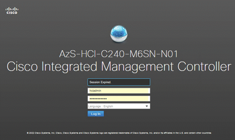
Step 8. Open a web browser on a computer on the same network.
Step 9. Enter the IMC IP address of the Cisco UCS C240 M6 Server: http://<<var_cimc_ip_address>.
Step 10. Enter the login credentials as updated in the IMC configuration.
Procedure 2. Synchronize Cisco UCS C240 Servers to NTP
Note: These steps provide the details for synchronizing the Cisco UCS environment to the NTP server.
Step 1. Log back into Cisco IMC using a URL that starts with https://.
Step 2. Select the Admin at the bottom of the left window and expand.
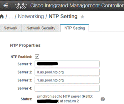
Step 3. Select Networking > NTP Setting.
Step 4. Select NTP Enabled check box to enable and enter the NTP server addresses.
Claim Cisco UCS C240 Standalone Servers in Cisco Intersight
Procedure 1. Cisco Intersight Device Claim – Register Cisco IMC to Cisco Intersight
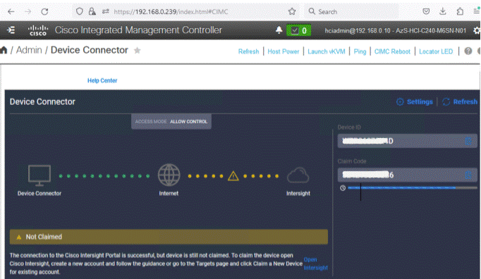
Step 1. From the Cisco IMC, go to Admin > Device connector.
Step 2. On the right side of the screen, click Settings.
Step 3. From Settings, go to the General tab and enable the Device connector. For the Access Mode, select Allow control and enable Tunneled vKVM.
Note: Tunneled vKVM is supported only for Cisco UCS C-Series servers with an Advantage or Premier license. Tunneled vKVM can be launched to complete OS installation from Cisco Intersight.
Step 4. Verify reachability to Cisco Intersight is updated after configuring DNS, NTP and Proxy Settings.
Step 5. Copy the Device ID and Claim Code.
Step 6. Create a Cisco Intersight account—go to https://intersight.com/ to create your Intersight account. You must have a valid Cisco ID to create a Cisco Intersight account. If you do not have a Cisco ID, create one by clicking Sign Up.
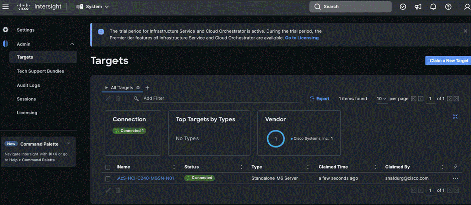
Step 7. After Logging in, from the Service Selector drop-down list, select System as shown below:
Step 8. Navigate to ADMIN > Targets and click Claim a New Target.
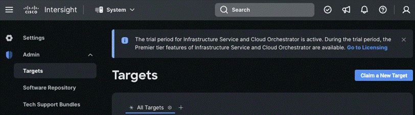
The Select Target Type window is displayed.
Step 9. In the filter column, select Compute / Fabric and select Cisco UCS Server (Standalone), and then click Start.
Step 10. Enter the Device ID and Claim Code obtained from Cisco IMC.
Step 11. Click Claim.
The Cisco UCS Server instance will be added to Intersight.
Step 12. Switch back to Cisco IMC to confirm that the device is claimed. Click Refresh to update the status.
![]()
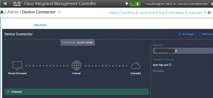
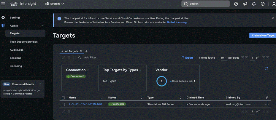
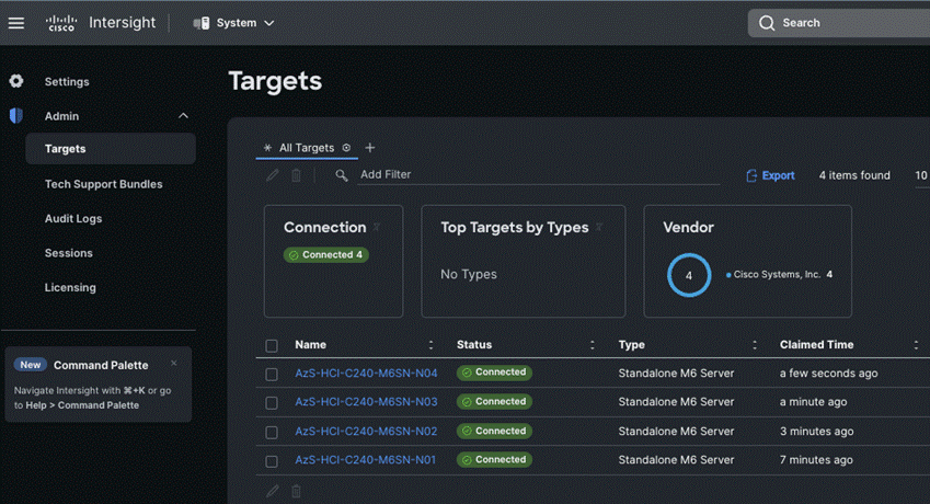
Step 13. Repeat steps 1 - 12 to claim other devices. After the targets are claimed, you can view the managed targets in the Targets table view.
Step 14. Navigate to Settings > Admin > Licensing and register the license to assign Essential, Advanced, or Premier license for Cisco Intersight.
For more information about the different license tiers for Cisco Intersight, go to: Cisco Intersight License Management.
Configure Cisco UCS C240 Standalone Servers using Cisco Intersight
Procedure 1. Upgrade Cisco IMC firmware for Cisco UCS C240 from Cisco Intersight
Step 1. From the Service Selector drop-down list, select Infrastructure Service.
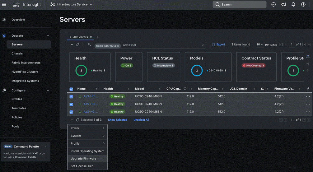
Step 2. Navigate to Operate > Servers, to launch the Servers Table view and select all the servers that require CIMC firmware upgrade.
Step 3. Click the ellipses below the selected servers and click Upgrade Firmware.
Step 4. On the Upgrade Firmware page, click Start.
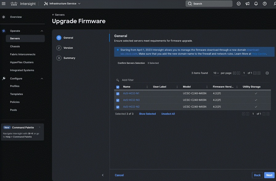
Step 5. On the General page, select all the Servers and click Next.
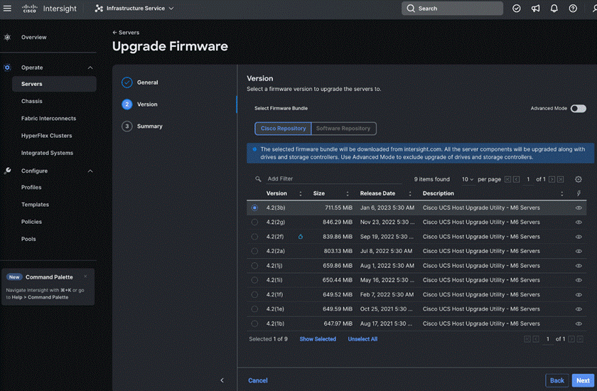
Step 6. On the Version page, enable the Advanced Mode to exclude upgrade of drives and storage controllers:
◦ Exclude Drives—Check this box to exclude upgrade of drives.
◦ Exclude Storage Controllers—Check this box to exclude upgrade of storage controllers.
Note: To exclude storage controller, ensure that the firmware version of Cisco IMC and the target upgrade firmware version is 4.1(3a) or later release.
Step 7. On the Version page under Cisco Repository, select a firmware version bundle from the list below to upgrade the servers to and click Next.
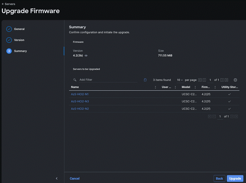
Step 8. On the Summary page, confirm the configuration and click Upgrade to initiate the upgrade.
For more information on upgrading Cisco UCS C-Series Standalone Servers Firmware, go to: Before you begin.
The upgrade workflow proceeds based on the selected reboot option.
Configure Policies to Create Server Profile
Note: These steps can also be completed at the time of the Server Profile creation.
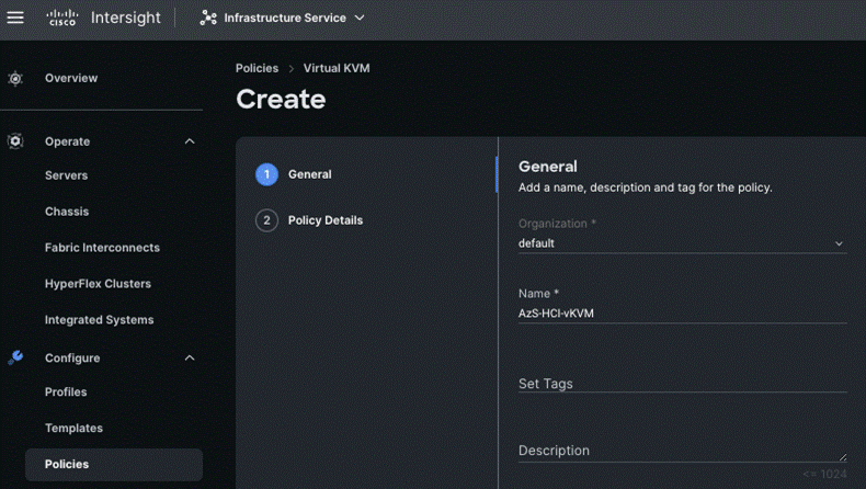
Procedure 2. Create Virtual KVM Policy
Step 1. From the Service Selector drop-down list, select Infrastructure Services and navigate to Configure > Policies and click Create Policy.
Step 2. On the Create page for Policies, select UCS Server > Virtual KVM and click Start.
Step 3. On the Virtual KVM Create page, enter the Organization, Name, Description and create a new tag or assign an existing tag and click Next.
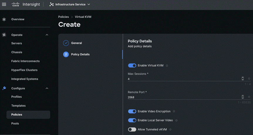
Step 4. On the Policy Details page, enable Allow Tunneled vKVM, and other options as shown below and click Create.
Procedure 3. Create Network Connectivity Policy
Step 1. From the Service Selector drop-down list, select Infrastructure Services and navigate to Configure > Policies and click Create Policy.
Step 2. On the Create page for Policies, select UCS Server > Network Connectivity and click Start.
Step 3. On the Network Connectivity Create page, enter the Organization, Name, Description and create a new tag or assign an existing tag and click Next.
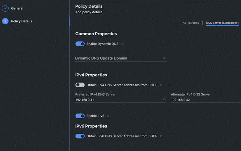
Step 4. On the Policy Details page, enter the preferred IPv4 DNS server addresses and configure other options as shown below and click Create.
Procedure 4. Create SSH Policy
Step 1. From the Service Selector drop-down list, select Infrastructure Services and navigate to Configure > Policies and click Create Policy.
Step 2. On the Create page for Policies, select UCS Server > SSH and click Start.
Step 3. On the SSH Create page, enter the Organization, Name, Description and create a new tag or assign an existing tag and click Next.
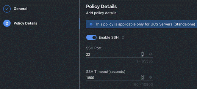
Step 4. On the Policy Details page, Enable SSH and click Create.
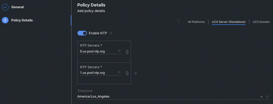
Procedure 5. Create NTP Policy
Step 1. From the Service Selector drop-down list, select Infrastructure Services and navigate to Configure > Policies and click Create Policy.
Step 2. On the Create page for Policies, select UCS Server > NTP and click Start.
Step 3. On the NTP Create page, enter the Organization, Name, Description and create a new tag or assign an existing tag and click Next.
Step 4. On the Policy Details page, Enable NTP, enter the NTP Server addresses and select a TimeZone. Click Create.
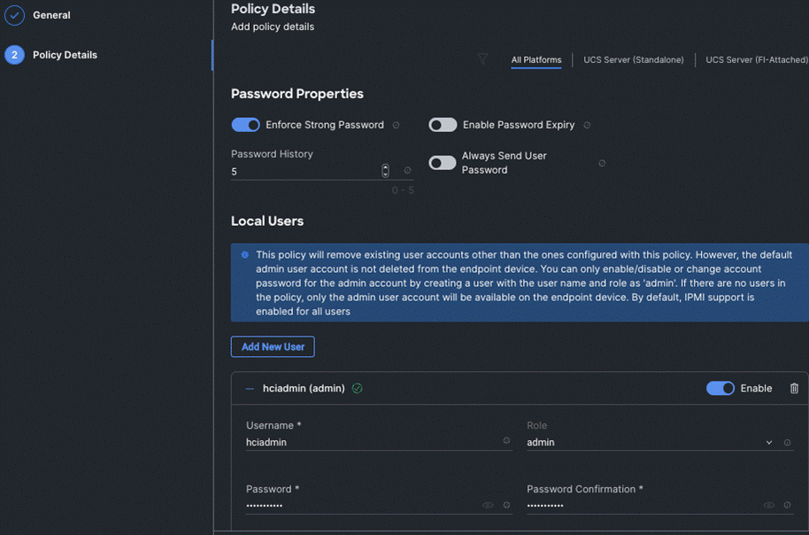
Procedure 6. Create Local User Policy
Step 1. From the Service Selector drop-down list, select Infrastructure Services and navigate to Configure > Policies and click Create Policy.
Step 2. On the Create page for Policies, select UCS Server > Local User and click Start.
Step 3. On the Local User Create page, enter the Organization, Name, Description and create a new tag or assign an existing tag and click Next.
Step 4. On the Policy Details page, Configure Password Properties and Add New User. Click Create.
Procedure 7. Create Local User Policy
Step 1. From the Service Selector drop-down list, select Infrastructure Services and navigate to Configure > Policies and click Create Policy.
Step 2. On the Create page for Policies, select UCS Server > Virtual Media and click Start.
Step 3. On the Virtual Media Create page, enter the Organization, Name, Description and create a new tag or assign an existing tag and click Next.
Step 4. On the Policy Details page, Enable Virtual Media and other properties if required. Click Create.
Procedure 8. Create Boot Order Policy
Step 1. From the Service Selector drop-down list, select Infrastructure Services and navigate to Configure > Policies and click Create Policy.
Step 2. On the Create page for Policies, select UCS Server > Boot Order and click Start.
Step 3. On the Boot Order Create page, enter the Organization, Name, Description and create a new tag or assign an existing tag and click Next.
Step 4. On the Policy Details page, Enable Secure Boot and from the Add Boot Device drop-down list, select the boot devices.
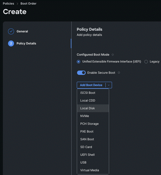
Step 5. Select Local Disk and Virtual Media and enter the details as shown in the below and click Create.
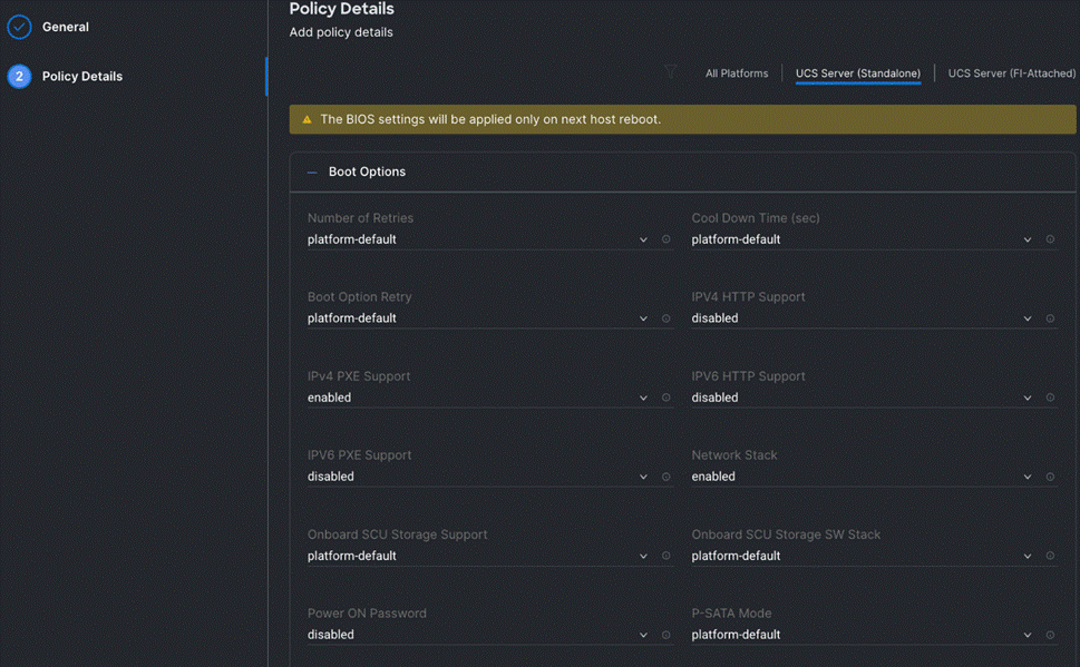
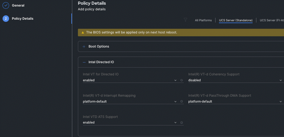
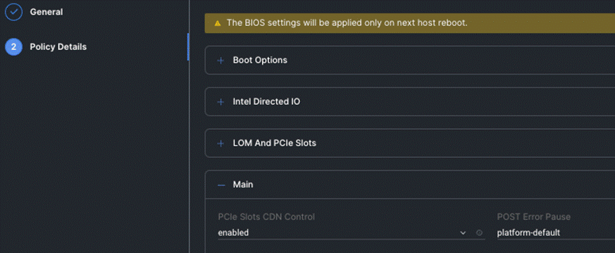
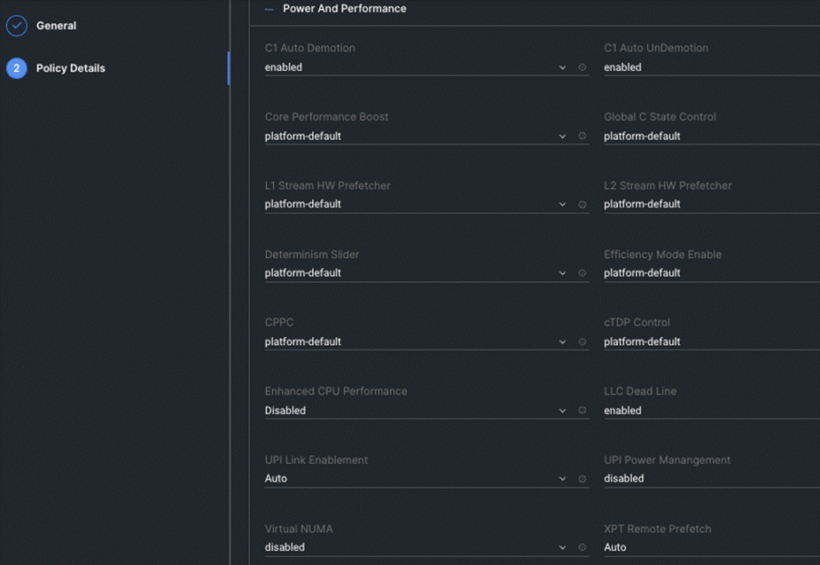
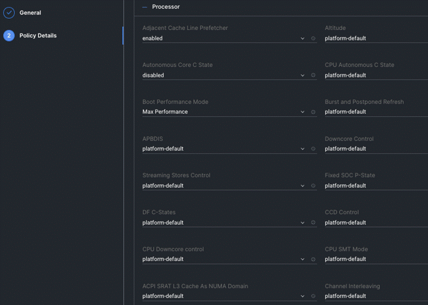
Procedure 9. Create BIOS Policy
Step 1. From the Service Selector drop-down list, select Infrastructure Services and navigate to Configure > Policies and click Create Policy.
Step 2. On the Create page for Policies, select UCS Server > BIOS and click Start.
Step 3. On the BIOS Create page, enter the Organization, Name, Description and create a new tag or assign an existing tag and click Next.
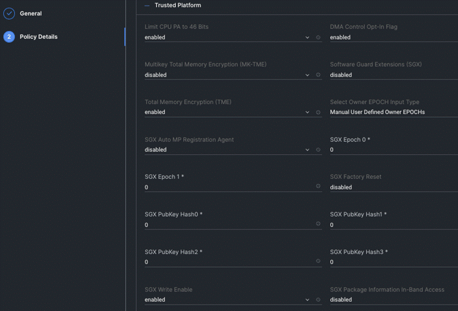
Step 4. On the Policy Details page, configure the tokens as shown in the below images, leaving the rest to defaults:
Procedure 10. Create Storage Policy
Step 1. From the Service Selector drop-down list, select Infrastructure Services and navigate to Configure > Policies and click Create Policy.
Step 2. On the Create page for Policies, select UCS Server > Storage and click on Start.
Step 3. On the Storage Create page, enter the Organization, Name, Description and create a new tag or assign an existing tag and click Next.
Step 4. On the Policy Details page, Enable the M.2 RAID Configuration and select the MSTOR RAID-1 (MSTOR RAID) from the drop-down list as shown in the below figure:
Procedure 11. Create UCS Server Profile
This procedure explains how to create a Cisco UCS server profile, clone it, and deploy servers.
Alternatively, you can create a server profile template from which multiple server profiles can be derived and deployed on servers. For more information on server profile templates, go to: https://intersight.com/help/saas/resources/cisco_intersight_managed_mode_configuration#server_profile_templates
Step 1. From the Service Selector drop-down list, select Infrastructure Services and navigate to Configure > Profiles and click Create UCS Server Profile.
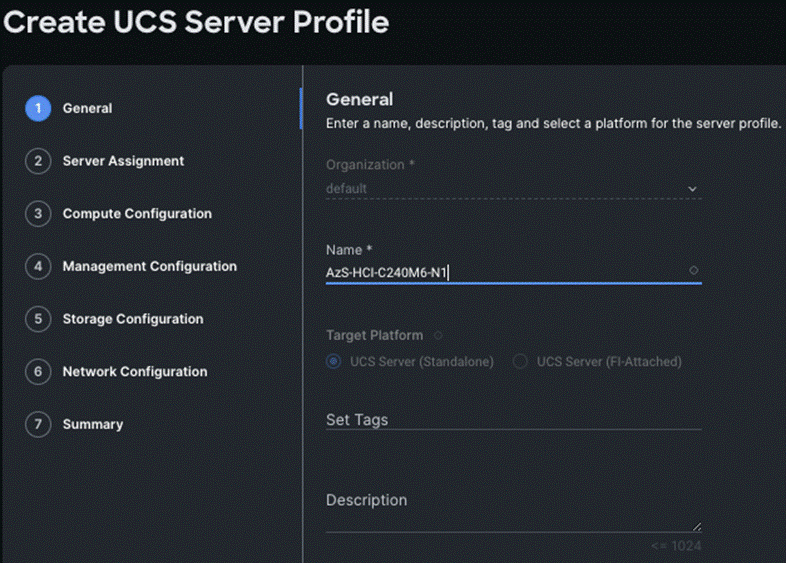
Step 2. On the Create UCS Server Profile page, click Start.
Step 3. On the General page, enter the Organization, Name, Description and create a new tag or assign an existing tag. For Target Platform, select UCS Standalone under and click Next.
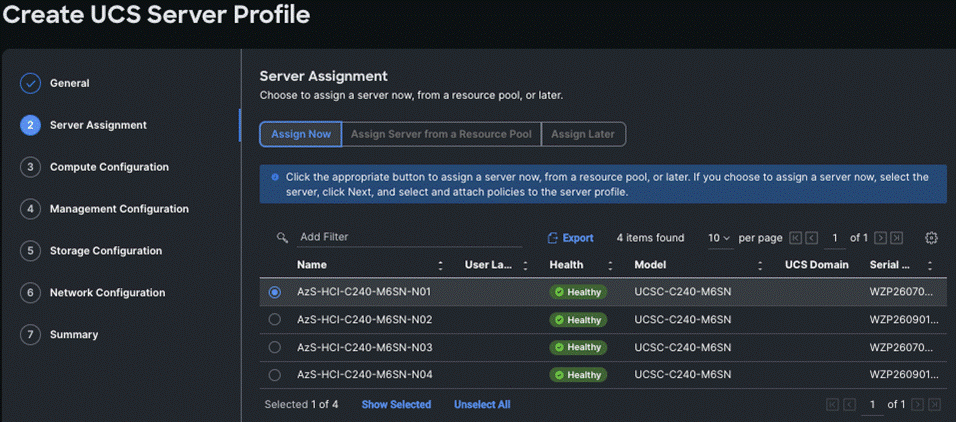
Step 4. On the Server Assignment page, click Assign Now and select a server from the list below:
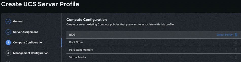
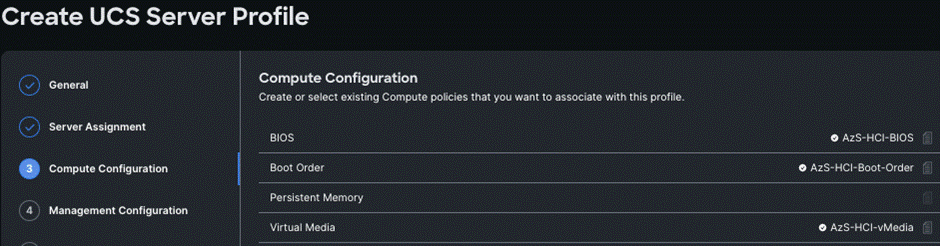
Step 5. On the Compute Configuration page, hover the mouse cursor over right-side of the row next to BIOS and click Select Policy.
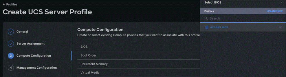
Step 6. Select the policy created for BIOS in the previous section.
Step 7. Select the respective policies created in the previous sections for Boot Order and Virtual Media as shown below and click Next.
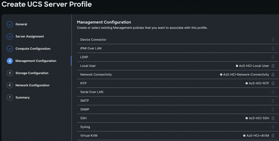
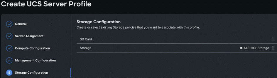
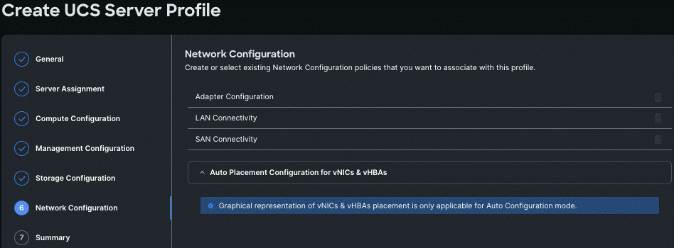
Step 8. Repeat steps 1 - 7 and complete the Management, Storage, and Network configuration and click Next.
Step 9. On the Summary page, verify the configuration and click Deploy.
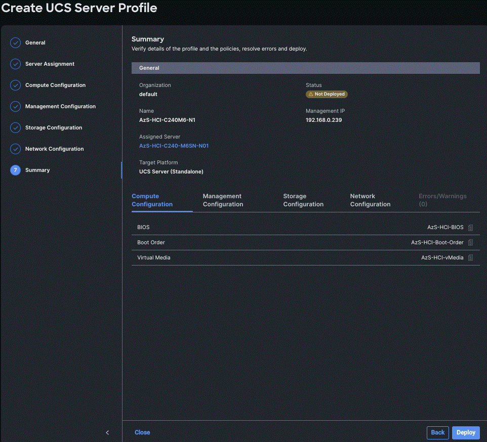
Deployment will take few minutes to complete, and the progress can be seen by clicking the Requests icon next to the Search field. The following figures show the status of the successfully deployed profile from Profile and Servers tab:
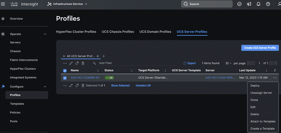
Step 10. Clone the Profile created in the previous steps, by clicking the ellipsis and selecting Clone as shown below:
Step 11. On the General page, click Assign Now and select the remaining unassigned servers and click Next.
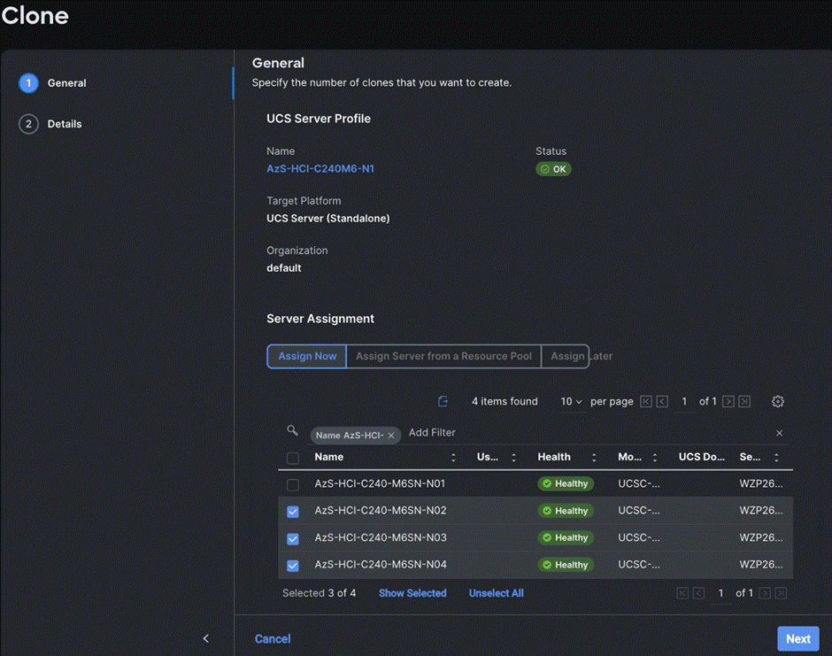
Step 12. On the Details page, edit the name under Clone Name Prefix and the number under the Start Index for Suffix as shown below and click Clone.
Step 13. On the Profiles page, select all the newly created profiles with Not Deployed status and click the ellipses. Click Deploy.
Step 14. On the Deploy pop-up page, click More Details to confirm, and click Deploy.
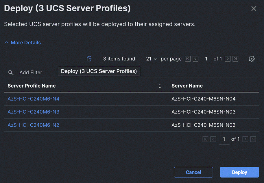
The following image shows the successfully deployed profiles on the assigned servers:
| VLAN Name |
VLAN ID |
| Management |
126 |
| Tenant |
100 |
| Storage-A |
107 |
| Storage-B |
207 |
Procedure 12. Launch Server KVM Instance to Install the Operating System
Launch KVM to each server after the service profile association is complete. Install the Azur Stack HCI OS 22H2 using PXE boot or a vMedia mapped installation ISO. PXE boot for OS installation is a better choice because the installation process will run much faster where multiple servers can perform OS installation concurrently.
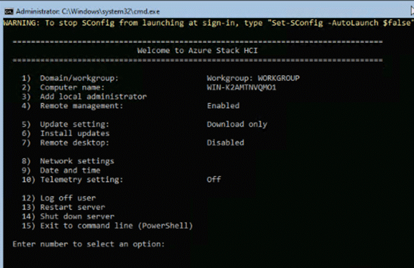
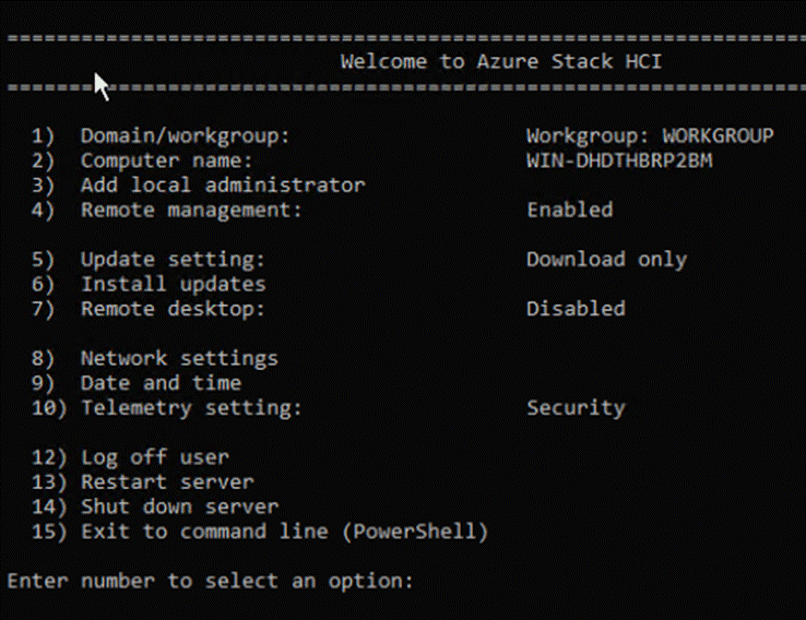
Step 1. Open a KVM session to each host and perform the following configuration to enable remote access to each host. After logging in, start PowerShell by selecting option 15 (Exit to command line (PowerShell)) in the SConfig screen.
Note: Each host must have a unique host name and IP address for your environment. The following is a table of host names and IP addresses used in this deployment.
| Host Name |
IP Address |
| AzS-HCI1-M6-N1 |
192.168.126.21 |
| AzS-HCI-Host02 |
192.168.126.22 |
| AzS-HCI-Host03 |
192.168.126.23 |
| AzS-HCI-Host04 |
192.168.1.24 |
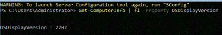
Procedure 13. Verify the Operating System Version
Step 1. Run the command Get-ComputerInfo | fl -Property OSDisplayVersion:
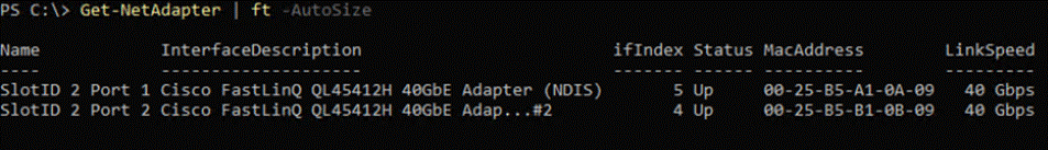
Procedure 14. Verify Available NICs Seen by the Operating System
Step 1. Run the command Get-NetAdapter | ft -AutoSize:
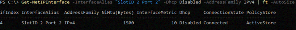
Procedure 15. Disable DHCP on Port 2 of the NIC and Verify the Setting
Step 1. Run the commands Set-NetIPInterface -InterfaceAlias "SlotID 2 Port 2" -Dhcp Disabled and Get-NetIPInterface -InterfaceAlias "SlotID 2 Port 2" -Dhcp Disabled -AddressFamily IPv4 | ft -AutoSize:
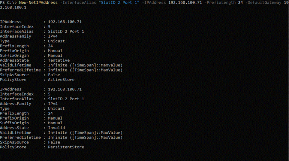
Procedure 16. Configure Static NIC IP Address for Management NIC’s
Note: Replace the IP address with the address specific to your environment.
Note: The VLAN for this subnet must be set to Native because VLAN tagging is not configured for this physical interface.
Step 1. Run the following command:
New-NetIPAddress -InterfaceAlias "SlotID 2 Port 1" -IPAddress 192.168.100.71 -PrefixLength 24 -DefaultGateway 192.168.100.1
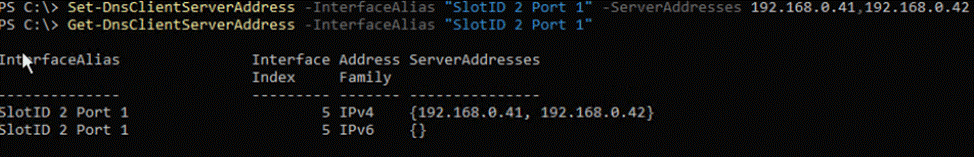
Procedure 17. Configure DNS Client Server IP Address
Note: Replace the DNS Server IP address with the address specific to your environment.
Step 1. Run the following commands:
Set-DnsClientServerAddress -InterfaceAlias "SlotID 2 Port 1" -ServerAddresses 192.168.0.41,192.168.0.42
Get-DnsClientServerAddress -InterfaceAlias "SlotID 2 Port 1"
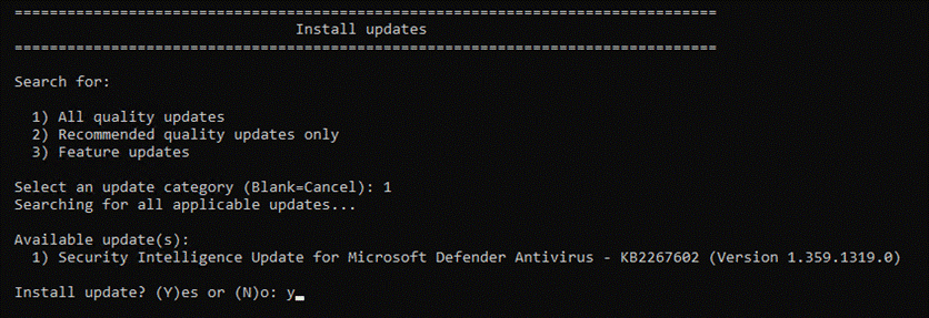
Procedure 18. Install Operating System Updates
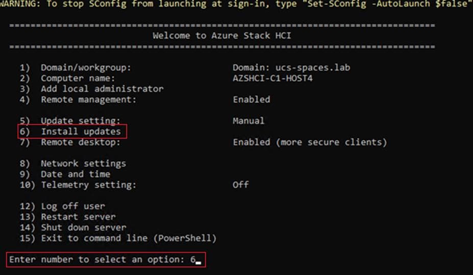
Step 1. Select option 6 Install Updates from the SConfig Menu.
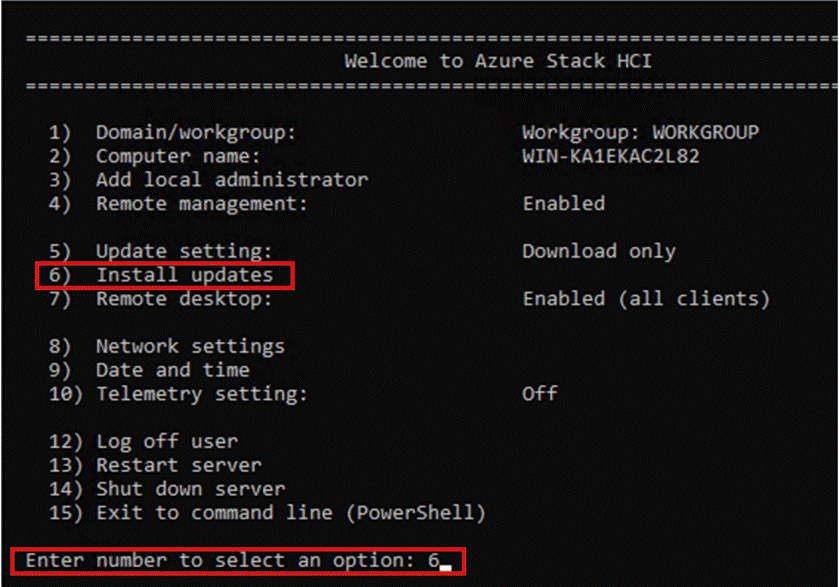
Step 2. Select option 2 All recommended quality updates only from the Install Updates menu.
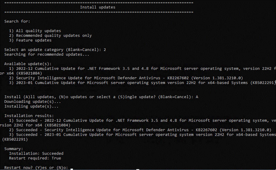
Step 3. Select the option A to install all recommended quality updates.
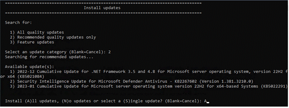
The updates will start downloading and installing.
Step 4. Select the option Y to reboot the server if a reboot is required after the update is installed.
Step 5. After the server reboots, login again and select option 6 Install Updates again from the SConfig Menu.
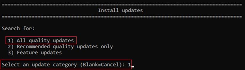
Step 6. Select option 1 All quality updates from the Install Updates menu.

Step 7. Select option A to install all updates if there are any available listed and reboot the server
Step 8. Repeat steps 1 - 7 after the server reboots to install any remaining updates
Note: The Cisco update installation may result in an error condition. This error can safely be ignored.
Step 9. After the server reboots, login again and select option 6 Install Updates again from the SConfig Menu.
Step 10. Select option 1 All quality updates form the Install Updates menu.
Step 11. Verify that no other quality updates are available for installation. Install any remaining quality updates.
Step 12. Return to the main SConfig menu.
Step 13. Select option 15 Exit to command line (PowerShell) in the SConfig screen.
Procedure 19. Rename Computer
Step 1. Run the command:
Rename-Computer -NewName AzS-HCI1-N11 -Restart
![]()
The server restarts after renaming the computer.
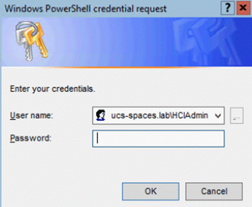
Procedure 20. Join the Windows Server to a Domain
Note: Replace the Active Directory Domain name with the domain name and account with domain admin privileges that is specific to your environment. Login with administrative privileges after the server reboot and enter option 15 to start a PowerShell session in the SConfig screen.
Note: The local computer time must be withing 5 minutes of the domain controller time in order the for the computer to join the active directory domain. The local computer date and time can be checked and adjusted using option 9 “Date and Time” in SConfig or by using the PowerShell Get-Date and Set-Date cmdlet.
Step 1. Run the following command to join the computer to the Active Directory domain:
Add-Computer -DomainName ucs-spaces.lab -Credential ucs-spaces.lab\HCIAdmin -Restart
![]()
The server restarts after joining the domain.
Note: The following procedures are preformed from a domain joined remote management Host. See the Appendix for Remote Management Host configuration requirements.
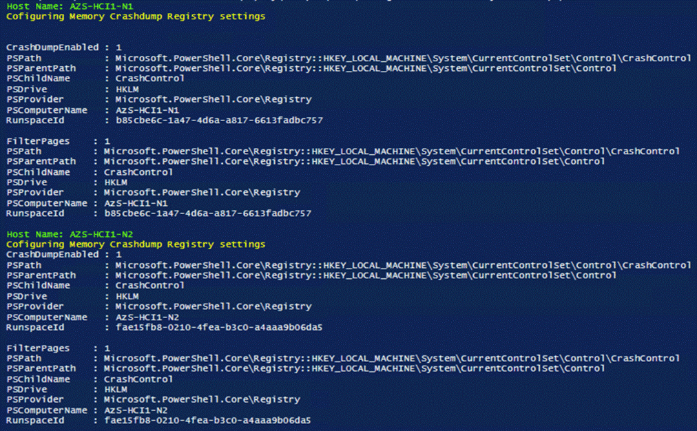
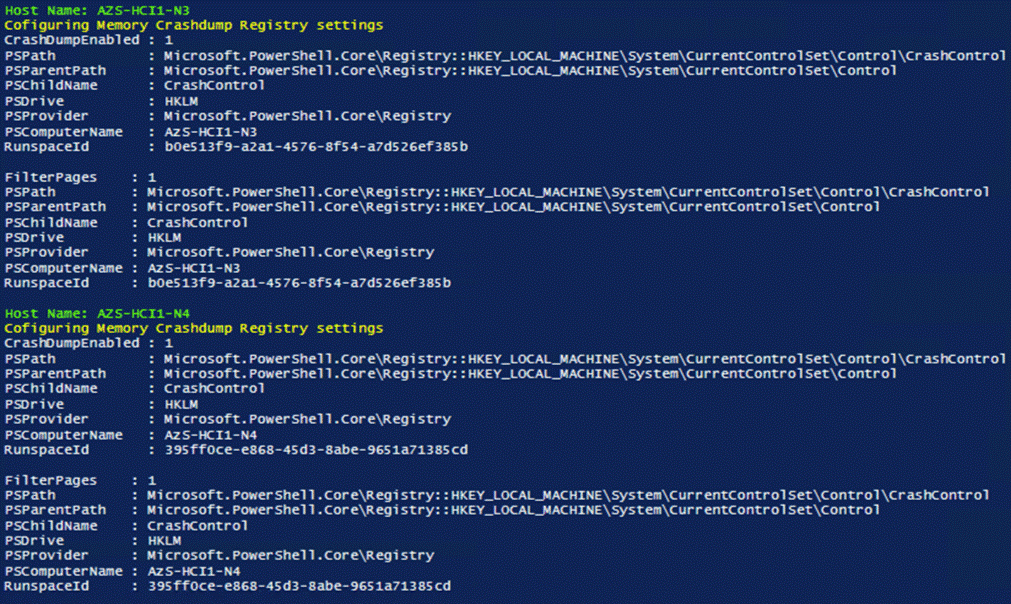
Procedure 21. Configure Windows Memory Crashdump
Note: Hyper-V hosts allocate typically contain a considerable amount of physical memory, but the majority of the physical memory is allocated to virtual machines. For this reason, the parent partition of a Hyper-V host uses a relatively small amount of memory as compared to the total amount of memory installed in the system. The memory dump of the parent partition can provide vital debugging information in the rare case that an unexpected bugcheck (bluescreen) occurs on host.
The following setting enables the creation of a memory dump file and when a bugcheck occurs and use the Active Dump setting to optimize the amount of memory used when a memory dump is created:
$Creds = Get-Credential -Message "Enter Login Credentials" -User ucs-spaces\hciadmin
$nodes = ("AzS-HCI1-N1", "AzS-HCI1-N2", "AzS-HCI1-N3", "AzS-HCI1-N4")
foreach ($node in $nodes) {
Invoke-Command $node -Credential $Creds -scriptblock {
write-host "Host Name:" $env:COMPUTERNAME -ForegroundColor Green
Write-Host "Cofiguring Memory Crashdump Registry settings " -ForegroundColor Yellow
Set-ItemProperty -Path HKLM:\System\CurrentControlSet\Control\CrashControl –Name CrashDumpEnabled -value 1
Set-ItemProperty -Path HKLM:\System\CurrentControlSet\Control\CrashControl –Name FilterPages -value 1
Get-ItemProperty -Path HKLM:\System\CurrentControlSet\Control\CrashControl -Name CrashDumpEnabled
Get-ItemProperty -Path HKLM:\System\CurrentControlSet\Control\CrashControl -Name FilterPages
}
}
Procedure 22. Configure Time Zone
Step 1. Time zone must have the same setting on all cluster nodes. The following script block configures the time zone:
$nodes = ("AzS-HCI1-N1", "AzS-HCI1-N2", "AzS-HCI1-N3", "AzS-HCI1-N4")
foreach ($node in $nodes) {
Invoke-Command $node -Credential $Creds -ScriptBlock {
write-host "Host Name:" $env:COMPUTERNAME -ForegroundColor Green
Write-Host "Configuring time zone..." -ForegroundColor Yellow
Set-Timezone -Name "Pacific Standard Time"
}
}
Note: The time zone is specific to the region. The following command lists available time zones.
Get-TimeZone -ListAvailable | ft StandardName, ID
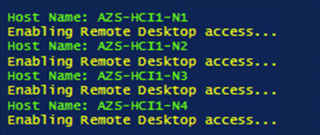
Procedure 23. Enable Remote Desktop Access on the Host Servers
Step 1. Run the following:
$nodes = ("AzS-HCI1-N1", "AzS-HCI1-N2", "AzS-HCI1-N3", "AzS-HCI1-N4")
foreach ($node in $nodes) {
Invoke-Command $node -Credential $Creds -ScriptBlock {
write-host "Host Name:" $env:COMPUTERNAME -ForegroundColor Green
Write-Host "Enabling Remote Desktop access..." -ForegroundColor Yellow
Set-ItemProperty -Path "HKLM:\System\CurrentControlSet\Control\Terminal Server" -Name "fDenyTSConnections" –Value 0
Enable-NetFirewallRule -DisplayGroup "Remote Desktop"
}
}
Procedure 24. Install Windows Features
The following Windows features are installed:
● Bitlocker
● Data Center Bridging
● Failover Clustering
● Hyper-V
● Hyper-V PowerShell
● Active Directory Remote Management PowerShell
● Cluster Management PowerShell
● File Server
● SMB Bandwidth Limit
● NetworkATC
● NetworkHUD
● FS-Data-Deduplication
$nodes = ("AzS-HCI1-N1", "AzS-HCI1-N2", "AzS-HCI1-N3", "AzS-HCI1-N4")
foreach ($node in $nodes) {
Invoke-Command $node -Credential $Creds -scriptblock {
write-host "Host Name:" $env:COMPUTERNAME -ForegroundColor Green
Write-Host "Enabling Required Windows Features and Restarting Host Server..." -ForegroundColor Yellow
Add-WindowsFeature -Name Hyper-V,Failover-Clustering,Data-Center-Bridging,Bitlocker,FS-FileServer, FS-SMBBW, Hyper-V-PowerShell,RSAT-AD-Powershell,RSAT-Clustering-PowerShell,NetworkATC,NetworkHUD,FS-DATA-Deduplication -IncludeAllSubFeature -IncludeManagementTools -Restart
}
}
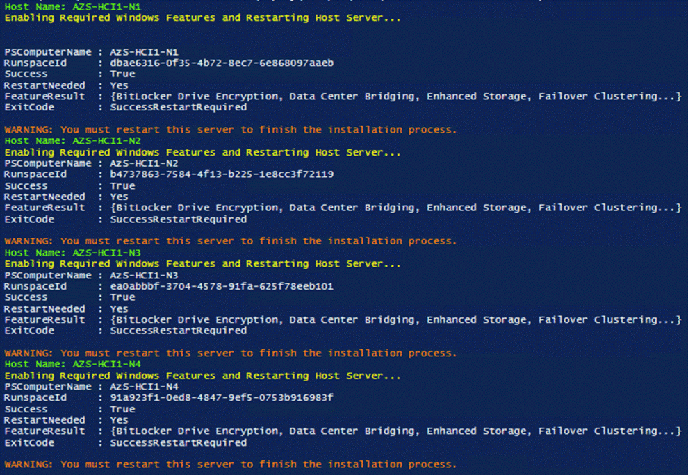
Note: Each server node will reboot automatically to complete the feature installation process. Confirm that each server reboots successfully.
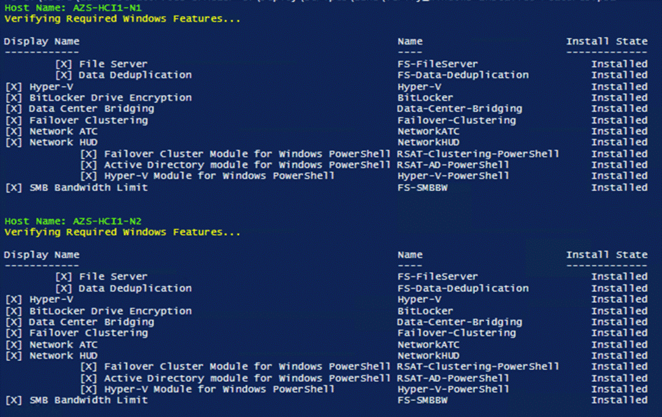
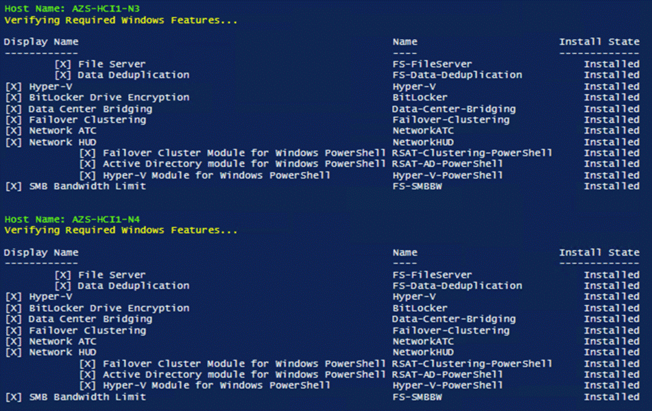
Procedure 25. Verify installed Windows Features
Step 1. Run the following:
$nodes = ("AzS-HCI1-N1", "AzS-HCI1-N2", "AzS-HCI1-N3", "AzS-HCI1-N4")
foreach ($node in $nodes) {
Invoke-Command $node -Credential $Creds -scriptblock {
write-host "Host Name:" $env:COMPUTERNAME -ForegroundColor Green
Write-Host "Verifying Required Windows Features..." -ForegroundColor Yellow
Get-WindowsFeature -Name Hyper-V,Failover-Clustering,Data-Center-Bridging,Bitlocker,FS-FileServer, FS-SMBBW,Hyper-V-PowerShell,RSAT-AD-Powershell,RSAT-Clustering-PowerShell,NetworkATC,NetworkHUD,FS-DATA-Deduplication | ft -AutoSize
}
}
Configure Bitlocker for System Volume
Using Bitlocker to encrypt system volume is an optional procedure in the deployment. TPM will be the primary key protector for the encrypted volume. The TPM will automatically decrypt the system volume at boot time. A recovery password will be an additional key protector in case the TPM fails. The recovery password will be backed up and stored in Active Directory Domain Service. Refer to the Appendix section to configure Bitlocker.
Configure Secured-Core on Hosts
Cisco UCS C240 M6 validated node is designed for Secured-Core Server, which allows your Azure Stack HCI investment to run workloads on a highly secure infrastructure with unparalleled levels of host security enabled with TPM 2.0, Secure boot, virtualization based security (VBS), boot DMA guard, and DRTM protection. This section explains the how-to build an infrastructure for the Secured-Core Server on Azure Stack HCI.
Procedure 1. Verify BIOS Setting
Step 1. Make sure the BIOS token “DMA Control Opt-In Flag” is enabled in the BIOS policy.
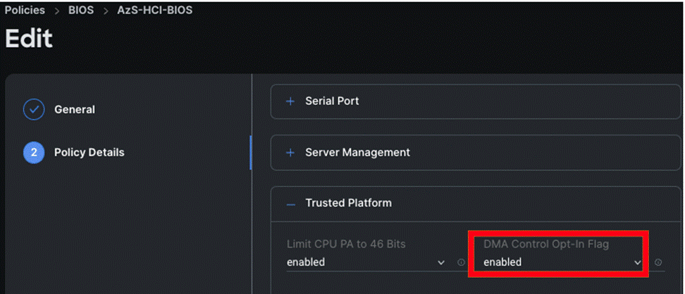
Note: The other required BIOS tokens for Secured-Core is enabled by default.
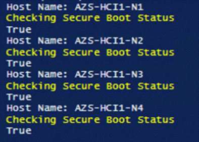
Procedure 2. Verify that Secure Boot is Enabled
Step 1. Run the following:
$nodes = ("AzS-HCI1-N1", "AzS-HCI1-N2", "AzS-HCI1-N3", "AzS-HCI1-N4")
foreach ($node in $nodes) {
Invoke-Command $node -Credential $Creds -scriptblock {
write-host "Host Name:" $env:COMPUTERNAME
Write-Host "Checking Secure Boot Status " -ForegroundColor Yellow
Confirm-SecureBootUEFI
}
}
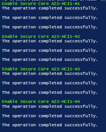
Procedure 3. Configure Secure Core
Step 1. Run the following to restart servers:
$nodes = ("AzS-HCI1-N1", "AzS-HCI1-N2", "AzS-HCI1-N3", "AzS-HCI1-N4")
foreach ($node in $nodes) {
Invoke-Command $node -Credential $Creds -scriptblock {
write-host "Enable Secure Core" $env:COMPUTERNAME -ForegroundColor Green
reg add "HKLM\SYSTEM\CurrentControlSet\Control\DeviceGuard\Scenarios\HypervisorEnforcedCodeIntegrity" /v "Enabled" /t REG_DWORD /d 1 /f
reg add "HKLM\SYSTEM\CurrentControlSet\Control\DeviceGuard\Scenarios\HypervisorEnforcedCodeIntegrity" /v "WasEnabledBy" /t REG_DWORD /d 0 /f
reg add "HKLM\SYSTEM\CurrentControlSet\Control\DeviceGuard\Scenarios\SystemGuard" /v "Enabled" /t REG_DWORD /d 1 /f
}
}
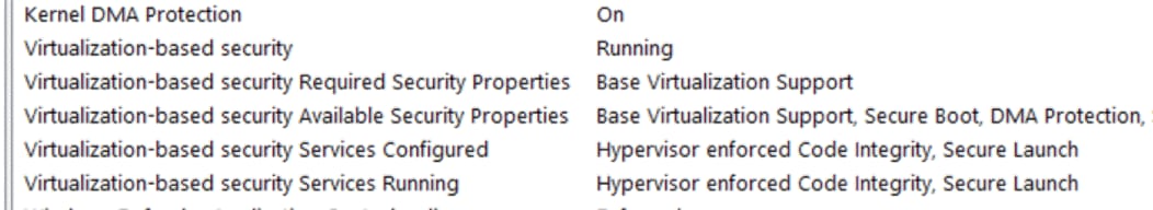
Step 2. Verify the Secured-core configuration:
Launch msinfo32 from command prompt and confirm the following values:
![]()
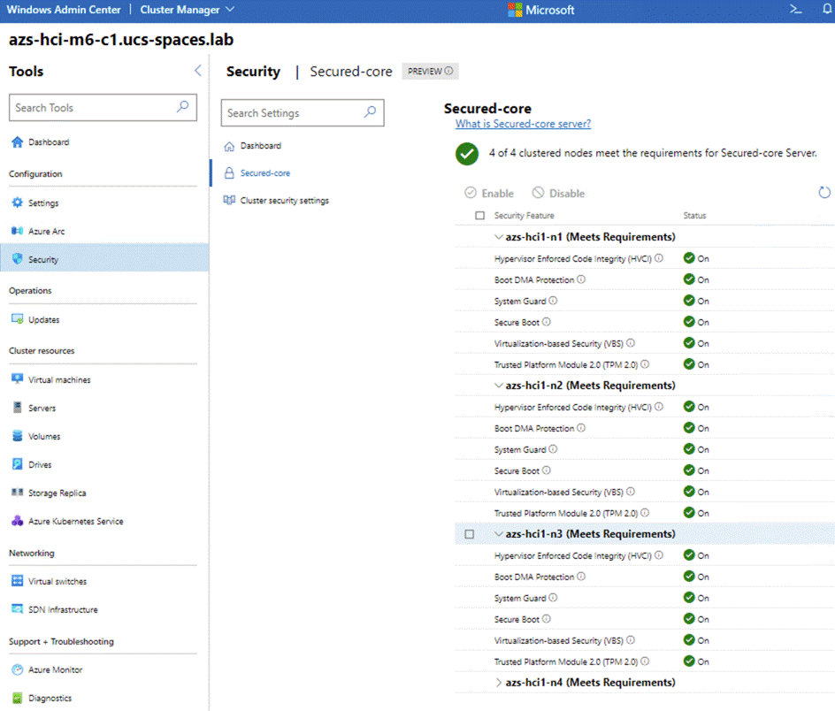
Or download and install Windows Admin Center (WAC). Add target cluster (or server) for management in WAC and from the Server/Cluster Manager view, select Security (left-pane) under Configuration and click Secured-core:
The subject contains the following procedures:
● Identify Physical Network Card Port Names
● Create and Deploy Standalone Network ATC Intent
● Verify Network ATC Intent Status
● Verify Virtual Switch and Virtual NIC Creation in the Parent Partition
● Verify SET Switch Team Load Balancing Algorithm
● Configure Default Route Metric for Management NIC in Parent Partition
● Configure Static NIC IP Address for Storage NICs
● Verify NIC IP Address for Storage NICs
● Verify DNS Registration is Removed for Storage Interfaces
● Enable Preserving 802.1p Priority Marking to Pass Through the vSwitch
● Verify the Storage vNIC VLANs
● Verify RDMA and RoCEv2 Protocol is Enabled on Physical NICs
● Verify that RDMA is Enabled on the Storage vNIC Adapters
● Verify the Mapping of each SMB-Direct NIC to the respective Fabric
Procedure 1. Identify Physical Network Card Port Names
Step 1. Run the following:
$nodes = ("AzS-HCI1-N1", "AzS-HCI1-N2", "AzS-HCI1-N3", "AzS-HCI1-N4")
foreach ($node in $nodes) {
Invoke-Command $node -Credential $Creds -scriptblock {
write-host "Host Name:" $env:COMPUTERNAME -ForegroundColor Green
Write-Host " Retrieving physical NIC port names " -ForegroundColor Yellow
Get-netadapter | ft Name, InterfaceDescription, Status, MacAddress, LinkSpeed
}
}
Note: If the NIC port names are “Ethernet” and “Ethernet 2”, CDN is not enabled. CDN (Consistent Device Naming) must be enabled for correct physical to virtual NIC mapping later in this guide.
Procedure 2. Create and Deploy Standalone Network ATC Intent
Step 1. Run the following script block to create a virtual switch with SET enabled and three virtual NICs:
$nodes = ("AzS-HCI1-N1", "AzS-HCI1-N2", "AzS-HCI1-N3", "AzS-HCI1-N4")
foreach ($node in $nodes) {
Invoke-Command $node -Credential $Creds -scriptblock {
write-host "Host Name:" $env:COMPUTERNAME -ForegroundColor Green
Write-Host " Create and Deploy Standalone Network ATC Intent " -ForegroundColor Yellow
$QoSOverride = New-NetIntentQoSPolicyOverRides
$AdapterOverride = New-NetIntentAdapterPropertyOverrides
$storageOverride = new-NetIntentStorageOverrides
$QoSOverride.PriorityValue8021Action_SMB = 4
$QoSOverride.PriorityValue8021Action_Cluster = 5
$AdapterOverride.NetworkDirectTechnology = 4
$storageOverride.EnableAutomaticIPGeneration = $false
$QoSOverride
$AdapterOverride
$storageOverride
Add-NetIntent -AdapterName "SlotID 2 Port 1", "SlotID 2 Port 2" -Management -Compute -Storage -StorageVlans 107, 207 -QoSPolicyOverrides $QoSOverride -AdapterPropertyOverrides $AdapterOverride -StorageOverrides $storageoverride -Name Mgmt_Compute_Storage
}
}
Procedure 3. Verify Network ATC Intent Status
Step 1. Run the following:
$nodes = ("AzS-HCI1-N1", "AzS-HCI1-N2", "AzS-HCI1-N3", "AzS-HCI1-N4")
foreach ($node in $nodes) {
Invoke-Command $node -Credential $Creds -scriptblock {
write-host "Host Name:" $env:COMPUTERNAME -ForegroundColor Green
Write-Host " Checking Network ATC Intent Status" -ForegroundColor Yellow
Get-netIntentStatus -ComputerName $node | ft Host,IntentName,ConfigurationStatus,ProvisioningStatus,IsComputeIntentSet,IsManagementIntentSet,IsStorageIntentset,IsStretchIntentSet
}
}
Procedure 4. Verify Virtual Switch and Virtual NIC Creation in the Parent Partition
$nodes = ("AzS-HCI1-N1", "AzS-HCI1-N2", "AzS-HCI1-N3", "AzS-HCI1-N4")
foreach ($node in $nodes) {
Invoke-Command $node -Credential $Creds -scriptblock {
write-host "Host Name:" $env:COMPUTERNAME -ForegroundColor Green
Write-Host " Verifying Virtual Switch " -ForegroundColor Yellow
Get-VMSwitch | fl Name, SwitchType, NetAdapterInterfaceDescription, NetAdapterInterfaceDescriptions
Write-Host " Verifying Management vNIC in parent partition " -ForegroundColor Yellow
Get-netadapter | ft Name, InterfaceDescription, Status, MacAddress, LinkSpeed
}
}
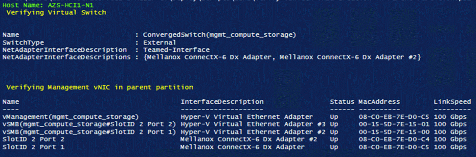
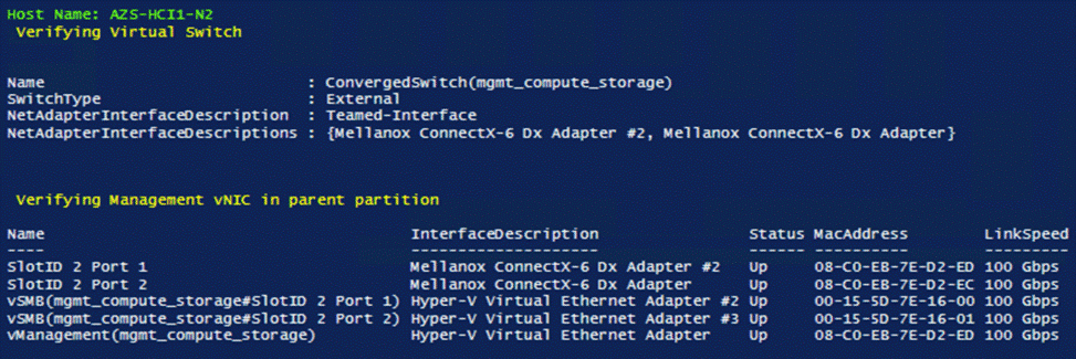
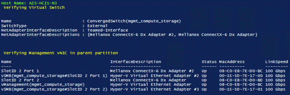
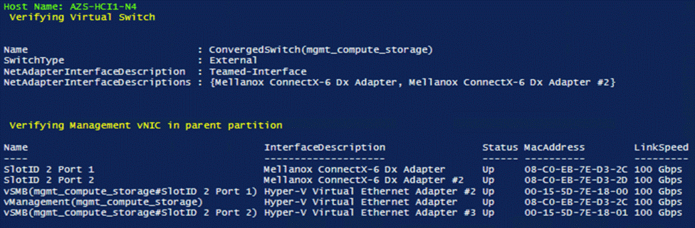
Note: There will be a brief network disconnect on each server node when VM switch binds to the physical adapters.
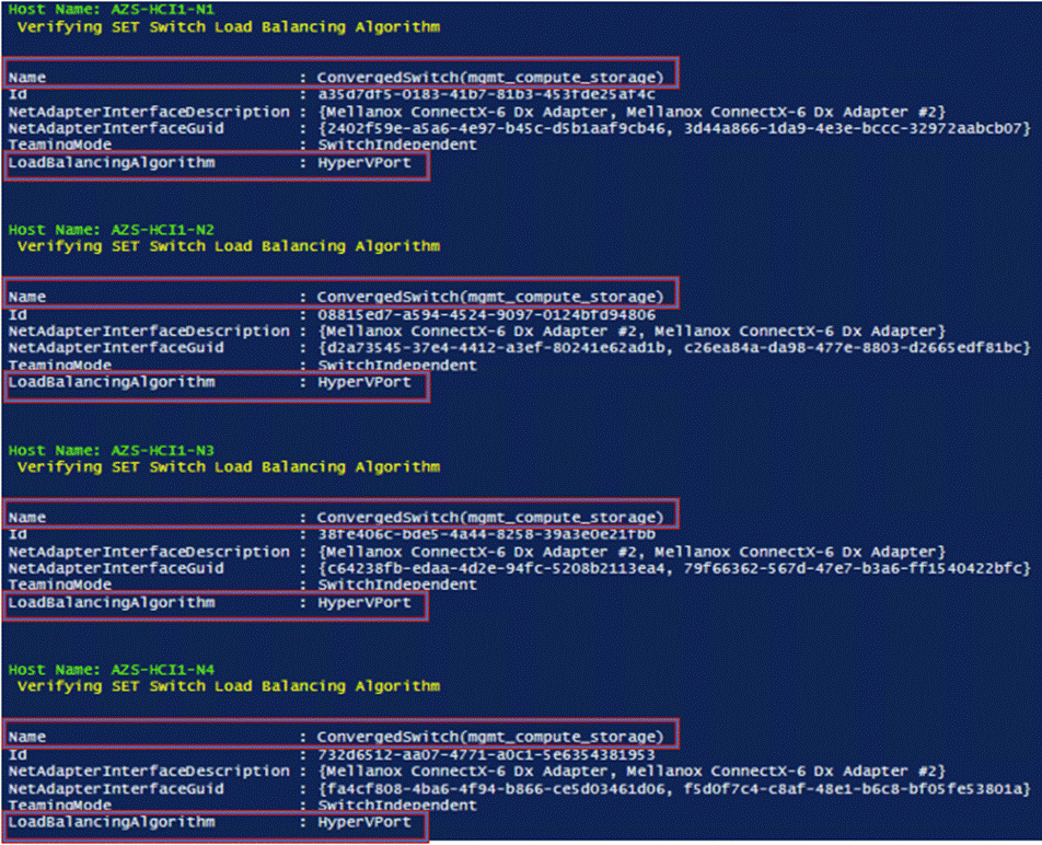
Procedure 5. Verify SET Switch Team Load Balancing Algorithm
Note: The load balancing algorithm must be a Hyper-V Port. Each VM switch must be bound to both physical network adapters.
$nodes = ("AzS-HCI1-N1", "AzS-HCI1-N2", "AzS-HCI1-N3", "AzS-HCI1-N4")
foreach ($node in $nodes) {
Invoke-Command $node -Credential $Creds -scriptblock {
write-host "Host Name:" $env:COMPUTERNAME -ForegroundColor Green
Write-Host " Verifying SET Switch Load Balancing Algorithm " -ForegroundColor Yellow
Get-VMSwitch | Get-VMSwitchTeam | fl
}
}
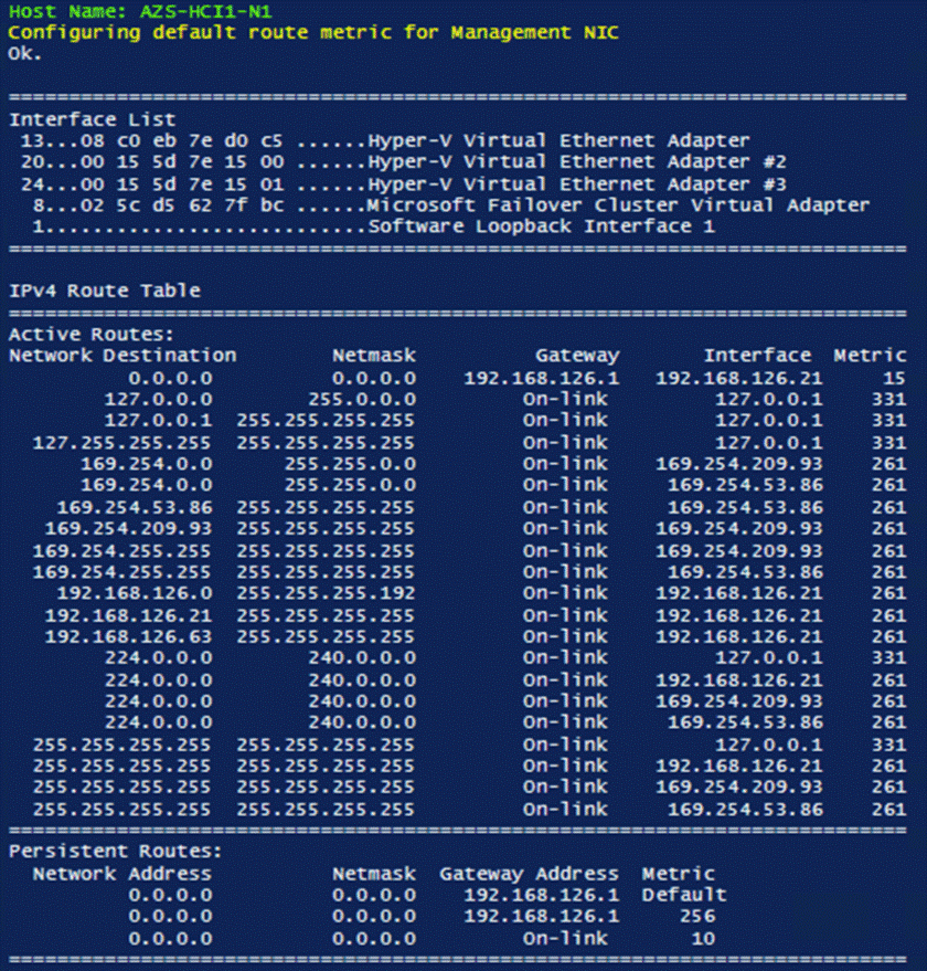
Procedure 6. Configure Default Route Metric for Management NIC in Parent Partition
Step 1. Run the following:
$nodes = ("AzS-HCI1-N1", "AzS-HCI1-N2", "AzS-HCI1-N3", "AzS-HCI1-N4")
foreach ($node in $nodes) {
Invoke-Command $node -Credential $Creds -scriptblock {
write-host "Host Name:" $env:COMPUTERNAME -ForegroundColor Green
Write-Host "Configuring default route metric for Management NIC " -ForegroundColor Yellow
netsh in ipv4 set ro 0.0.0.0/0 "vManagement(mgmt_compute_storage)” met=10
route print -4
}
}
Procedure 7. Configure Static NIC IP Address for Storage NIC’s
Note: Leave the gateway unconfigured for storage NICs.
| Host |
SMB NIC Name |
SMB NIC IP Address |
| AzS-HCI-Host01
|
SMB-A |
192.168.107.21 |
| SMB-B |
192.168.207.21 |
|
| AzS-HCI-Host02
|
SMB-A |
192.168.107.22 |
| SMB-B |
192.168.207.22 |
|
| AzS-HCI-Host03
|
SMB-A |
192.168.107.23 |
| SMB-B |
192.168.207.23 |
|
| AzS-HCI-Host04 |
SMB-A |
192.168.107.24 |
| SMB-B |
192.168.207.24 |
$nodes = ("AzS-HCI1-N1", "AzS-HCI1-N2", "AzS-HCI1-N3", "AzS-HCI1-N4")
$IPStorageNetA = "192.168.107." #vSMB(mgmt_compute_storage#SlotID 2 Port 1)networkaddress
$IPStorageNetB = "192.168.207." #vSMB(mgmt_compute_storage#SlotID 2 Port 2)networkaddress
$IPHostAddr = 21 #Starting host address
foreach ($node in $nodes) {
$session = New-CimSession -ComputerName $node
New-NetIPAddress -CimSession $session -InterfaceAlias "vSMB(mgmt_compute_storage#SlotID 2 Port 1)" -IPAddress ($IPStorageNetA+$IPHostAddr.ToString()) -PrefixLength 24
New-NetIPAddress -CimSession $session -InterfaceAlias "vSMB(mgmt_compute_storage#SlotID 2 Port 2)" -IPAddress ($IPStorageNetB+$IPHostAddr.ToString()) -PrefixLength 24
$IPHostAddr++
}
Get-CimSession | Remove-CimSession
Remove-Variable session
Note: Network connectivity may be temporarily disrupted during the following configuration operations, but connectivity will automatically recover.
Procedure 8. Verify NIC IP Address for Storage NICs
Step 1. Run the following:
$nodes = ("AzS-HCI1-N1", "AzS-HCI1-N2", "AzS-HCI1-N3", "AzS-HCI1-N4")
foreach ($node in $nodes) {
Invoke-Command $node -Credential $Creds -scriptblock {
write-host "Host Name:" $env:COMPUTERNAME -ForegroundColor Green
Write-Host "Verifying Storage NIC IP Address " -ForegroundColor Yellow
Get-NetIPConfiguration -InterfaceAlias vSMB* | fl InterfaceAlias, IPv4Address, IPv4DefaultGateway
}
}
Procedure 9. Verify DNS Registration is Removed for Storage Interfaces
Step 1. Run the following:
$nodes = ("AzS-HCI1-N1", "AzS-HCI1-N2", "AzS-HCI1-N3", "AzS-HCI1-N4")
foreach ($node in $nodes) {
Invoke-Command $node -Credential $Creds -scriptblock {
write-host "Host Name:" $env:COMPUTERNAME -ForegroundColor Green
Write-Host "Removing DNS Restistration from Storage NICs " -ForegroundColor Yellow
Set-DnsClient -InterfaceAlias "vSMB(mgmt_compute_storage#SlotID 2 Port 1)" -RegisterThisConnectionsAddress:$false
Set-DnsClient -InterfaceAlias "vSMB(mgmt_compute_storage#SlotID 2 Port 2)" -RegisterThisConnectionsAddress:$false
Get-DnsClient -InterfaceAlias "vSMB(mgmt_compute_storage#SlotID 2 Port 1)"| ft InterfaceAlias,RegisterThisConnectionsAddress
Get-DnsClient -InterfaceAlias "vSMB(mgmt_compute_storage#SlotID 2 Port 2)"| ft InterfaceAlias,RegisterThisConnectionsAddress
}
}
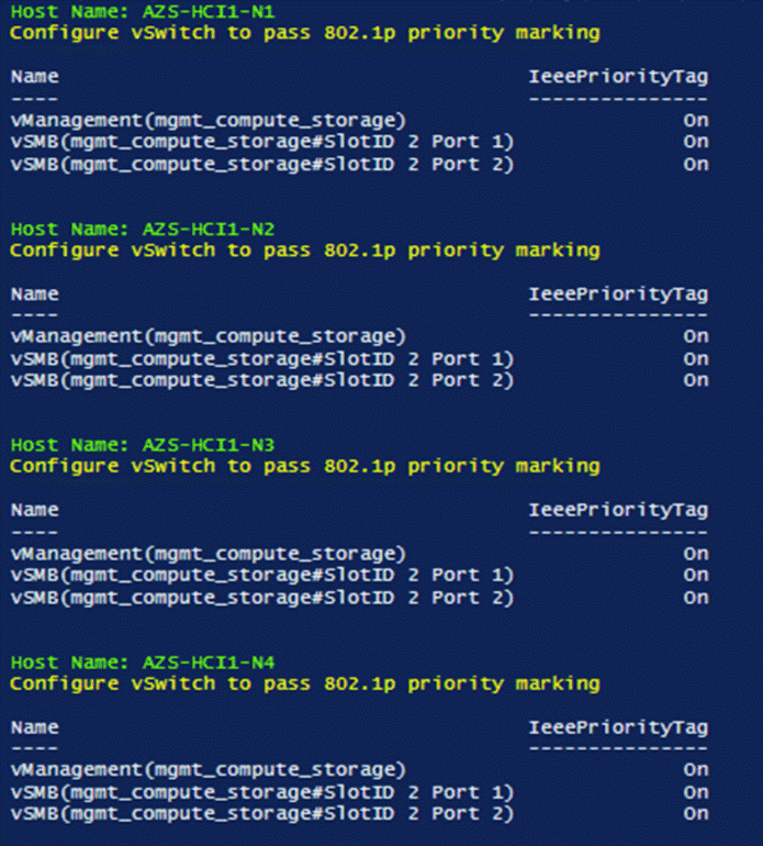
Procedure 10. Enable Preserving 802.1p Priority Marking to Pass Through the vSwitch
Note: The virtual switch zeros-out 802.1p priority marking in the packet header. This is the default behavior. Preserving the 802.1p priority marking in the packet header is required for classifying and prioritizing network traffic in the fabric and other northbound switches that have QoS policies configured. This setting affects prioritized network traffic traversing the virtual switch. This setting is required prioritizing Cluster Communication network traffic. RDMA traffic passing through RDMA enabled vNICs is not affected by this setting because this traffic bypasses the virtual switch and goes directly to the physical NIC.
Step 1. Run the following:
$nodes = ("AzS-HCI1-N1", "AzS-HCI1-N2", "AzS-HCI1-N3", "AzS-HCI1-N4")
foreach ($node in $nodes) {
Invoke-Command $node -Credential $Creds -scriptblock {
write-host "Host Name:" $env:COMPUTERNAME -ForegroundColor Green
Write-Host "Configure vSwitch to pass 802.1p priority marking " -ForegroundColor Yellow
Set-VMNetworkAdapter -Name “vManagement(mgmt_compute_storage)" -ManagementOS -IeeePriorityTag On
Get-VMNetworkAdapter -ManagementOS | ft Name,IeeePriorityTag
}
}
Procedure 11. Verify the Storage vNIC VLANs
Step 1. Run the following:
$nodes = ("AzS-HCI1-N1", "AzS-HCI1-N2", "AzS-HCI1-N3", "AzS-HCI1-N4")
foreach ($node in $nodes) {
Invoke-Command $node -Credential $Creds -scriptblock {
write-host "Host Name:" $env:COMPUTERNAME -ForegroundColor Green
Write-Host "Verify vNIC VLANs Configuration " -ForegroundColor Yellow
Get-VMNetworkAdapter -ManagementOS | Get-VMNetworkAdapterIsolation | FT IsolationMode, DefaultIsolationID, ParentAdapter -AutoSize
}
}
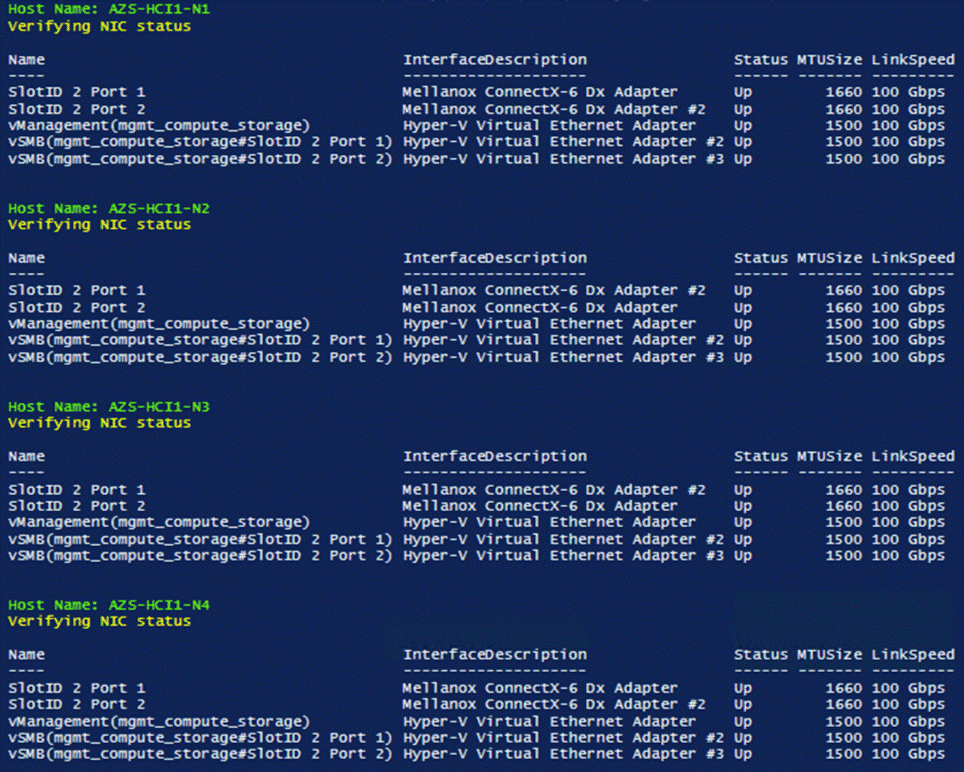
Procedure 12. Verify Network Adapters
Step 1. Run the following:
$nodes = ("AzS-HCI1-N1", "AzS-HCI1-N2", "AzS-HCI1-N3", "AzS-HCI1-N4")
foreach ($node in $nodes) {
Invoke-Command $node -Credential $Creds -scriptblock {
write-host "Host Name:" $env:COMPUTERNAME -ForegroundColor Green
Write-Host "Verifying NIC status " -ForegroundColor Yellow
Get-NetAdapter | sort Name | ft Name,InterfaceDescription,Status,MTUSize,LinkSpeed
}
}
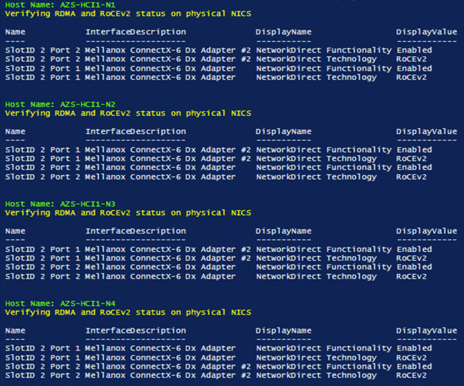
Procedure 13. Verify RDMA and RoCEv2 Protocol is Enabled on Physical NICs
Step 1. Run the following:
$nodes = ("AzS-HCI1-N1", "AzS-HCI1-N2", "AzS-HCI1-N3", "AzS-HCI1-N4")
foreach ($node in $nodes) {
Invoke-Command $node -Credential $Creds -scriptblock {
write-host "Host Name:" $env:COMPUTERNAME -ForegroundColor Green
Write-Host "Verifying RDMA and RoCEv2 status on physical NICS " -ForegroundColor Yellow
Get-NetAdapterAdvancedProperty -InterfaceDescription "Mellanox ConnectX*" -DisplayName "NetworkDirect*" | ft Name, InterfaceDescription,DisplayName,DisplayValue
}
}
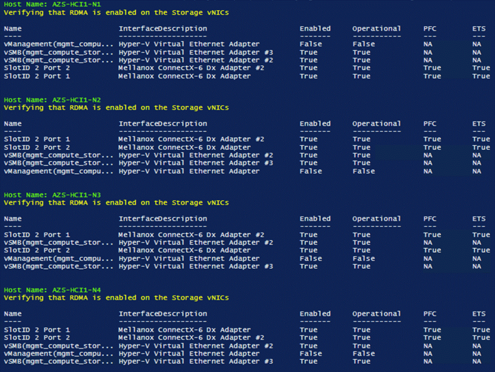
Procedure 14. Verify that RDMA is Enabled on the Storage vNIC Adapters
Step 1. Run the following:
$nodes = ("AzS-HCI1-N1", "AzS-HCI1-N2", "AzS-HCI1-N3", "AzS-HCI1-N4")
foreach ($node in $nodes) {
Invoke-Command $node -Credential $Creds -scriptblock {
write-host "Host Name:" $env:COMPUTERNAME -ForegroundColor Green
Write-Host "Verifying that RDMA is enabled on the Storage vNICs" -ForegroundColor Yellow
Get-NetAdapterRdma | ft
}
}
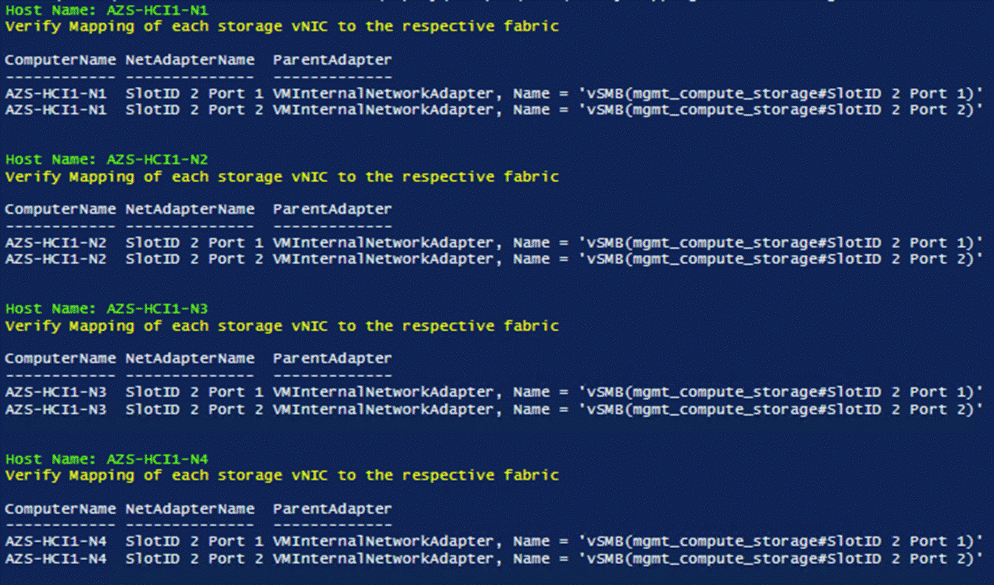
Procedure 15. Verify the Mapping of each SMB-Direct NIC to the respective Fabric
Step 1. Run the following:
$nodes = ("AzS-HCI1-N1", "AzS-HCI1-N2", "AzS-HCI1-N3", "AzS-HCI1-N4")
foreach ($node in $nodes) {
Invoke-Command $node -Credential $Creds -scriptblock {
write-host "Host Name:" $env:COMPUTERNAME -ForegroundColor Green
Write-Host "Verify Mapping of each storage vNIC to the respective fabric " -ForegroundColor Yellow
Get-VMNetworkAdapterTeamMapping -ManagementOS | ft ComputerName,NetAdapterName,ParentAdapter
}
}
Procedure 16. Verify RDMA Capabilities
Step 1. Run the following:
$nodes = ("AzS-HCI1-N1", "AzS-HCI1-N2", "AzS-HCI1-N3", "AzS-HCI1-N4")
foreach ($node in $nodes) {
Invoke-Command $node -Credential $Creds -scriptblock {
write-host "Host Name:" $env:COMPUTERNAME -ForegroundColor Green
Write-Host "Verify Storage vNIC RDMA operational status " -ForegroundColor Yellow
Get-SmbClientNetworkInterface | ft FriendlyName, RDMACapable
}
}
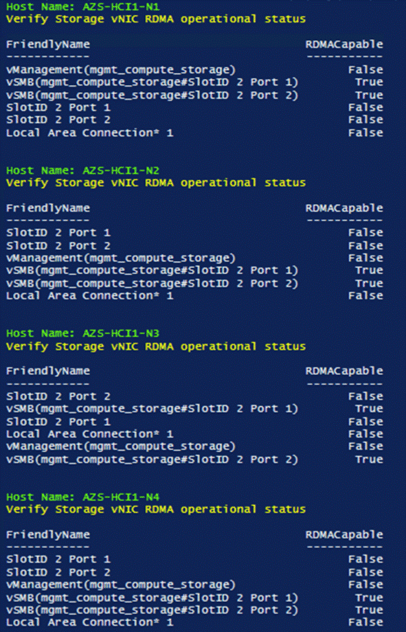
This subject has the following procedures:
● Verify Traffic Class Configuration on all Nodes
● Set DCBX Not Willing Mode on all Nodes
Procedure 1. Verify Traffic Class Configuration on all Nodes
Step 1. Run the following:
$nodes = ("AzS-HCI1-N1", "AzS-HCI1-N2", "AzS-HCI1-N3", "AzS-HCI1-N4")
foreach ($node in $nodes) {
Invoke-Command $node -Credential $Creds -scriptblock {
write-host "Host Name:" $env:COMPUTERNAME -ForegroundColor Green
Write-Host " Verifing Traffic Class Configuration " -ForegroundColor Yellow
Get-NetQosTrafficClass | ft -AutoSize
}
}
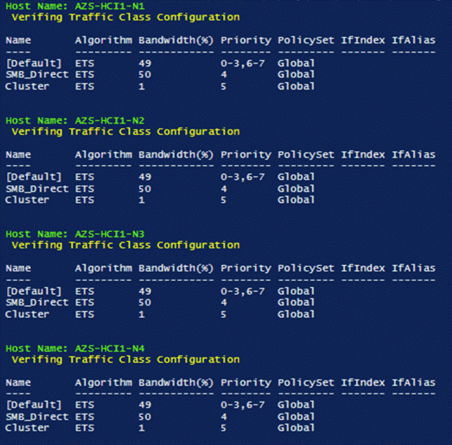
Procedure 2. Set DCBX Willing Mode on all Nodes
Step 1. Run the following:
Note: Server nodes need to be in Willing mode in order for DCBX auto negotiation to take place and Priority Flow Control to be enabled on the ToR Switch ports where Nodes are connected.
$nodes = ("AzS-HCI1-N1", "AzS-HCI1-N2", "AzS-HCI1-N3", "AzS-HCI1-N4")
foreach ($node in $nodes) {
Invoke-Command $node -Credential $Creds -scriptblock {
write-host "Host Name:" $env:COMPUTERNAME -ForegroundColor Green
Write-Host "Verifying that DCBX is set to Not Willing mode" -ForegroundColor Yellow
Get-netadapter | Get-NetQosDcbxSetting | ft InterfaceAlias, PolicySet, Willing
}
}
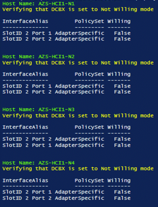
Prepare Server for Storage Spaces Direct
This subject contains the following procedures:
● Clean Inventory Storage Drives that will be used by Storage Spaces Direct
● Verify the Servers are ready for Storage Spaces Direct
Procedure 1. Run Windows Updates
IMPORTANT! It is extremely important to install the latest updated for Failover Cluster, Scale-Out Files Server, and Storage Spaces. Run Windows Update to install the latest updates after installing the Windows Features.
Note: The Cluster-Aware Updating role will be installed after the cluster is created. The cluster-aware updating is a feature that automates downloading and installing Windows Server updates on all cluster nodes.
Procedure 2. Clean Inventory Storage Drives that will be used by Storage Spaces Direct
Step 1. Run the following:
$nodes = ("AzS-HCI1-N1", "AzS-HCI1-N2", "AzS-HCI1-N3", "AzS-HCI1-N4")
foreach ($node in $nodes) {
Invoke-Command $node -Credential $Creds -scriptblock {
write-host "Host Name:" $env:COMPUTERNAME -ForegroundColor Green
Write-Host "Preparing disk for Storage Spaces Direct" -ForegroundColor Yellow
Write-Host Cleaning Storage Drives....
#Remove Exisiting virtual disks and storage pools
Update-StorageProviderCache
Get-StoragePool | ? IsPrimordial -eq $false | Set-StoragePool -IsReadOnly:$false -ErrorAction SilentlyContinue
Get-StoragePool | ? IsPrimordial -eq $false | Get-VirtualDisk | Remove-VirtualDisk -Confirm:$false -ErrorAction SilentlyContinue
Get-StoragePool | ? IsPrimordial -eq $false | Remove-StoragePool -Confirm:$false -ErrorAction SilentlyContinue
Get-PhysicalDisk | Reset-PhysicalDisk -ErrorAction SilentlyContinue
Get-Disk | ? Number -ne $null | ? IsBoot -ne $true | ? IsSystem -ne $true | ? PartitionStyle -ne RAW | % {
$_ | Set-Disk -isoffline:$false
$_ | Set-Disk -isreadonly:$false
$_ | Clear-Disk -RemoveData -RemoveOEM -Confirm:$false
$_ | Set-Disk -isreadonly:$true
$_ | Set-Disk -isoffline:$true
}
#Inventory Storage Disks
Get-Disk | Where Number -Ne $Null | Where IsBoot -Ne $True | Where IsSystem -Ne $True | Where PartitionStyle -Eq RAW | Group -NoElement -Property FriendlyName | ft
}
}
Procedure 3. Verify the Servers are ready for Storage Spaces Direct
Step 1. Run the following:
$CandidateClusterNode = "AzS-HCI1-N1"
Invoke-Command $CandidateClusterNode -Credential $Creds -scriptblock {
write-host "Host Name:" $env:COMPUTERNAME -ForegroundColor Green
Write-Host " Enabling CredSSP" -ForegroundColor Yellow
$Void = Enable-WSManCredSSP -Role Server -Force
}
Invoke-Command $CandidateClusterNode -Credential $Creds -authentication Credssp -scriptblock {
write-host "Host Name:" $env:COMPUTERNAME -ForegroundColor Green
$nodes = ("AzS-HCI1-N1", "AzS-HCI1-N2", "AzS-HCI1-N3", "AzS-HCI1-N4")
Write-Host " Validating Cluster Nodes..." -ForegroundColor Yellow
Test-Cluster -Node $nodes -Include "System Configuration",Networking,Inventory, “Storage Spaces Direct”
Write-Host " Disabling CredSSP" -ForegroundColor Yellow
Disable-WSManCredSSP -Role Server
Write-Host " Verifying that CredSSP are disabled on target server..." -ForegroundColor Yellow
Get-WSManCredSSP
}
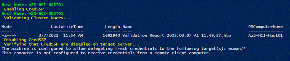
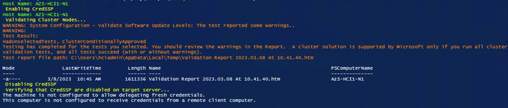
Step 2. Review the validation report and resolve all errors and warning before proceeding to create the Storage Spaces Direct Cluster:
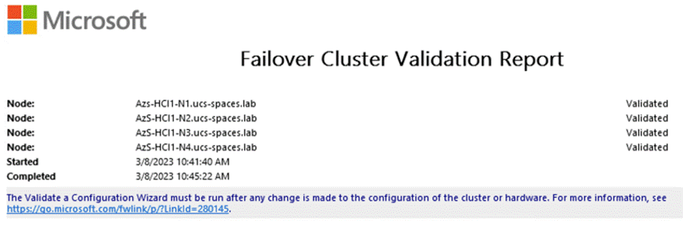
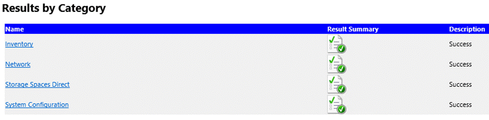
Configure Windows Failover Cluster
This subject contains the following procedures:
● Verify Status for Cluster Nodes after creating the Cluster
● Remove Standalone Network ATC Intent
● Create and Deploy Clustered Network ATC Intent
● Verify Clustered Network ATC Deployment and Status
● Verify Network Adapter Status after Network Intent Has Been Applied
● Verify Cluster Network Interfaces
● Configure Live Migration Network Isolation
● Get Management Cluster Network ID
● Exclude Management Network from Live Migration Network list
● Verify Live Migration Exclusion list
● Configure Live Migration to use SMB Protocol
● Configure Live Migration Bandwidth Limit
● Create Maximum Bandwidth Limit for Management vNIC
● Create the File Share for the Cluster Witness
● Configure File Share Witness
● Additional Cluster Quorum Witness Options
● Configure Cluster-Aware Updating
● Configure Kernel Soft Reboot for Cluster Aware Updating
Procedure 1. Create the Cluster
Step 1. Create the cluster with a static IP Address:
$CandidateClusterNode = "AzS-HCI1-N1"
Invoke-Command $CandidateClusterNode -Credential $Creds -scriptblock {
write-host "Host Name:" $env:COMPUTERNAME -ForegroundColor Green
Write-Host " Enabling CredSSP" -ForegroundColor Yellow
$Void = Enable-WSManCredSSP -Role Server -Force
}
Invoke-Command $CandidateClusterNode -Credential $Creds -authentication Credssp -scriptblock {
write-host "Host Name:" $env:COMPUTERNAME -ForegroundColor Green
$nodes = ("AzS-HCI1-N1", "AzS-HCI1-N2", "AzS-HCI1-N3", "AzS-HCI1-N4")
Write-Host " Creating the cluster..." -ForegroundColor Yellow
$Cluster = “AzS-HCI-M6-C1”
New-Cluster -Name $Cluster -Node $nodes -StaticAddress 192.168.126.25 –NoStorage
Get-Cluster | fl Name, SharedVolumesRoot
Write-Host " Disabling CredSSP" -ForegroundColor Yellow
Disable-WSManCredSSP -Role Server
Write-Host " Verifying that CredSSP are disabled on target server..." -ForegroundColor Yellow
Get-WSManCredSSP
}
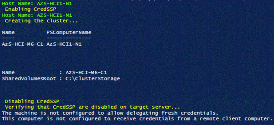
Procedure 2. Verify Status for Cluster Nodes after creating the Cluster
Step 1. Run the following:
$Cluster = “AzS-HCI-M6-C1”
Invoke-Command $Cluster -Credential $Creds -scriptblock {
write-host "Host Name:" $env:COMPUTERNAME -ForegroundColor Green
Write-Host " Enabling CredSSP" -ForegroundColor Yellow
$Void = Enable-WSManCredSSP -Role Server -Force
}
Invoke-Command $Cluster -Credential $Creds -authentication Credssp -scriptblock {
$Cluster = “AzS-HCI-M6-C1”
write-host "Host Name:" $env:COMPUTERNAME -ForegroundColor Green
Write-Host " Checking cluster nodes..." -ForegroundColor Yellow
Get-ClusterNode -Cluster $Cluster | ft Name, State, Type
Write-Host " Disabling CredSSP" -ForegroundColor Yellow
Disable-WSManCredSSP -Role Server
Write-Host " Verifying that CredSSP are disabled on target server..." -ForegroundColor Yellow
Get-WSManCredSSP
}
Procedure 3. Remove Standalone Network ATC Intent
Step 1. Run the following:
$Cluster = “AzS-HCI-M6-C1”
$nodes = (Get-ClusterNode -Cluster $Cluster).Name
foreach ($node in $nodes) {
Invoke-Command $node -scriptblock {
write-host "Host Name:" $env:COMPUTERNAME -ForegroundColor Green
Write-Host " Identifying and Removing Standalone Network ATC Intent " -ForegroundColor Yellow
$intent = Get-NetIntent | Where-Object {$_.Scope -Like 'Host' -and $_.IntentName -EQ 'mgmt_compute_storage'}
Write-Host "Removing Standalone Network ATC Intent $intent" -ForegroundColor Yellow
Remove-NetIntent -Name $intent.IntentName
}
}
Procedure 4. Create and Deploy Clustered Network ATC Intent
Step 1. Run the following:
$Cluster = “AzS-HCI-M6-C1”
Invoke-Command $Cluster -Credential $Creds -scriptblock {
write-host "Host Name:" $env:COMPUTERNAME -ForegroundColor Green
Write-Host " Enabling CredSSP" -ForegroundColor Yellow
$Void = Enable-WSManCredSSP -Role Server -Force
}
Invoke-Command $Cluster -Credential $Creds -authentication Credssp -scriptblock {
write-host "Host Name:" $env:COMPUTERNAME -ForegroundColor Green
Write-Host " Create and Deploy Clustered Network ATC Intent " -ForegroundColor Yellow
$ClusterName = Get-cluster
$QoSOverride = New-NetIntentQoSPolicyOverRides
$AdapterOverride = New-NetIntentAdapterPropertyOverrides
$storageOverride = new-NetIntentStorageOverrides
$QoSOverride.PriorityValue8021Action_SMB = 4
$QoSOverride.PriorityValue8021Action_Cluster = 5
$AdapterOverride.NetworkDirectTechnology = 4
$storageOverride.EnableAutomaticIPGeneration = $false
$QoSOverride
$AdapterOverride
$storageOverride
Add-NetIntent -AdapterName "SlotID 2 Port 1", "SlotID 2 Port 2" -Management -Compute -Storage -StorageVlans 107, 207 -QoSPolicyOverrides $QoSOverride -AdapterPropertyOverrides $AdapterOverride -StorageOverrides $storageoverride -Name Mgmt_Compute_Storage
Write-Host " Disabling CredSSP" -ForegroundColor Yellow
Disable-WSManCredSSP -Role Server
Write-Host " Verifying that CredSSP are disabled on target server..." -ForegroundColor Yellow
Get-WSManCredSSP
}
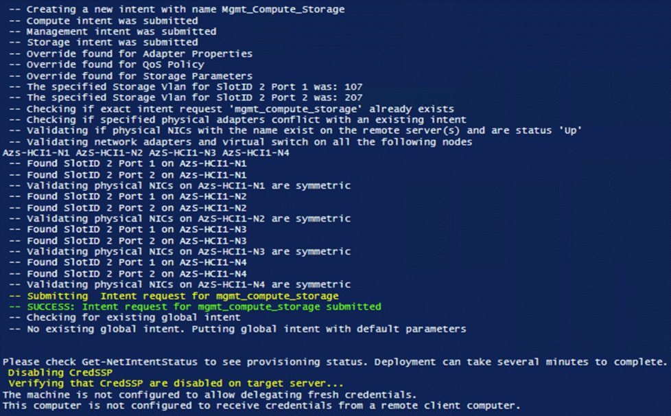
Procedure 5. Verify Clustered Network ATC Deployment and Status
$Cluster = “AzS-HCI-M6-C1”
Invoke-Command $Cluster -Credential $Creds -scriptblock {
write-host "Host Name:" $env:COMPUTERNAME -ForegroundColor Green
Write-Host " Enabling CredSSP" -ForegroundColor Yellow
$Void = Enable-WSManCredSSP -Role Server -Force
}
Invoke-Command $Cluster -Credential $Creds -authentication Credssp -scriptblock {
write-host "Host Name:" $env:COMPUTERNAME -ForegroundColor Green
Write-Host "Verify Clustered Network ATC Intent Status" -ForegroundColor Yellow
$ClusterName = (Get-cluster).Name
Get-NetIntent -ClusterName $ClusterName| Select IntentName,scope
Get-NetIntentStatus -ClusterName $ClusterName | Select Host, IntentName, ConfigurationStatus, ProvisioningStatus
Write-Host " Disabling CredSSP" -ForegroundColor Yellow
Disable-WSManCredSSP -Role Server
Write-Host " Verifying that CredSSP are disabled on target server..." -ForegroundColor Yellow
Get-WSManCredSSP
}
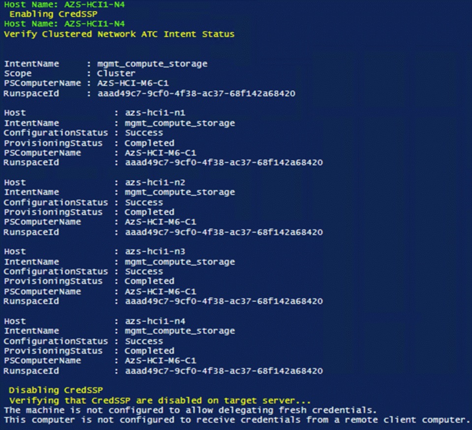
Note: It may take a few minutes for the network intent application to complete.
Procedure 6. Verify Network Adapter Status after Network Intent Has Been Applied
$nodes = (Get-ClusterNode -Cluster $Cluster).Name
foreach ($node in $nodes) {
Invoke-Command $node -Credential $Creds -scriptblock {
write-host "Host Name:" $env:COMPUTERNAME -ForegroundColor Green
Write-Host " Enabling CredSSP" -ForegroundColor Yellow
$Void = Enable-WSManCredSSP -Role Server -Force
Write-Host "Verifying NIC Port Status " -ForegroundColor Yellow
Get-netadapter | ft Name, InterfaceDescription, Status, MTUSize, MacAddress, LinkSpeed
Write-Host " Disabling CredSSP" -ForegroundColor Yellow
Disable-WSManCredSSP -Role Server
Write-Host " Verifying that CredSSP are disabled on target server..." -ForegroundColor Yellow
Get-WSManCredSSP
}
}
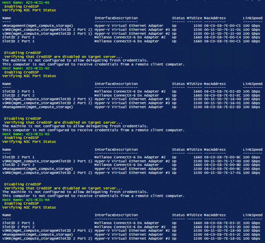
Procedure 7. Check Cluster Network Interfaces
Step 1. Check cluster networks:
$Cluster = “AzS-HCI-M6-C1"
Invoke-Command $Cluster -Credential $Creds -scriptblock {
write-host "Host Name:" $env:COMPUTERNAME -ForegroundColor Green
Write-Host " Enabling CredSSP" -ForegroundColor Yellow
$Void = Enable-WSManCredSSP -Role Server -Force
}
Invoke-Command $Cluster -Credential $Creds -authentication Credssp -scriptblock {
write-host "Host Name:" $env:COMPUTERNAME -ForegroundColor Green
Write-Host " Checking cluster networks " -ForegroundColor Yellow
$ClusterName = (Get-cluster).Name
Get-ClusterNetwork -Cluster $ClusterName | ft name,address,state,role –autosize
Write-Host " Disabling CredSSP" -ForegroundColor Yellow
Disable-WSManCredSSP -Role Server
Write-Host " Verifying that CredSSP are disabled on target server..." -ForegroundColor Yellow
Get-WSManCredSSP
}
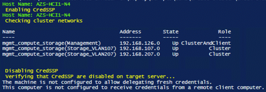
Procedure 8. Verify Cluster Network Interfaces
Step 1. Run the following:
$Cluster = “AzS-HCI-M6-C1"
Invoke-Command $Cluster -Credential $Creds -scriptblock {
write-host "Host Name:" $env:COMPUTERNAME -ForegroundColor Green
Write-Host " Enabling CredSSP" -ForegroundColor Yellow
$Void = Enable-WSManCredSSP -Role Server -Force
}
Invoke-Command $Cluster -Credential $Creds -authentication Credssp -scriptblock {
write-host "Host Name:" $env:COMPUTERNAME -ForegroundColor Green
Write-Host " Verifying cluster network interfaces " -ForegroundColor Yellow
$ClusterName = (Get-cluster).Name
Get-ClusterNetworkInterface -Cluster $ClusterName | sort Name | ft Network, Name
Write-Host " Disabling CredSSP" -ForegroundColor Yellow
Disable-WSManCredSSP -Role Server
Write-Host " Verifying that CredSSP are disabled on target server..." -ForegroundColor Yellow
Get-WSManCredSSP
}
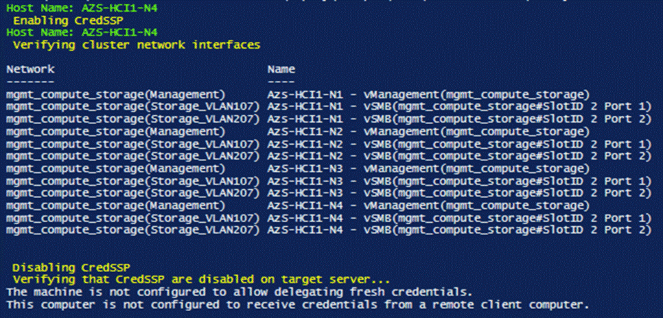
Procedure 9. Verify Live Migration Exclusion list
Step 1. Run the following to get Management Cluster Network ID:
$Cluster = “AzS-HCI-M6-C1”
Invoke-Command $Cluster -Credential $Creds -scriptblock {
write-host "Host Name:" $env:COMPUTERNAME -ForegroundColor Green
Write-Host " Enabling CredSSP" -ForegroundColor Yellow
$Void = Enable-WSManCredSSP -Role Server -Force
}
Invoke-Command $Cluster -Credential $Creds -authentication Credssp -scriptblock {
write-host "Host Name:" $env:COMPUTERNAME -ForegroundColor Green
Write-Host " Checking Management cluster network settings " -ForegroundColor Yellow
$ClusterName = (Get-cluster).Name
Get-ClusterNetwork -Cluster $ClusterName -Name “mgmt_compute_storage(Management)” | fl *
Write-Host " Disabling CredSSP" -ForegroundColor Yellow
Disable-WSManCredSSP -Role Server
Write-Host " Verifying that CredSSP are disabled on target server..." -ForegroundColor Yellow
Get-WSManCredSSP
}
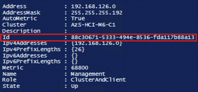
Step 2. Run the following to Verify Live Migration Exclusion List:
$Cluster = “AzS-HCI-M6-C1"
Invoke-Command $Cluster -Credential $Creds -scriptblock {
write-host "Host Name:" $env:COMPUTERNAME -ForegroundColor Green
Write-Host " Enabling CredSSP" -ForegroundColor Yellow
$Void = Enable-WSManCredSSP -Role Server -Force
}
Invoke-Command $Cluster -Credential $Creds -authentication Credssp -scriptblock {
write-host "Host Name:" $env:COMPUTERNAME -ForegroundColor Green
Write-Host " Verifying Management network exclusion from Live Migration Network list " -ForegroundColor Yellow
$ClusterName = (Get-cluster).Name
Get-ClusterResourceType -Cluster $ClusterName -Name "Virtual Machine" | Get-ClusterParameter -Name MigrationExcludeNetworks | fl *
Write-Host " Disabling CredSSP" -ForegroundColor Yellow
Disable-WSManCredSSP -Role Server
Write-Host " Verifying that CredSSP are disabled on target server..." -ForegroundColor Yellow
Get-WSManCredSSP
}
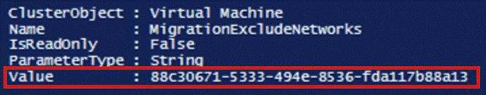
For more information, go to: https://technet.microsoft.com/en-us/library/dn550728(v=ws.11).aspx
Procedure 10. Configure Live Migration to use SMB Protocol
Note: SMB protocol provides the best throughput for Live Migration. The default setting is Compression which is best for constrained networks.
Step 1. Run the following:
$Cluster = “AzS-HCI-M6-C1"
$nodes = (Get-ClusterNode -Cluster $Cluster).Name
foreach ($node in $nodes) {
Invoke-Command $node -scriptblock {
write-host "Host Name:" $env:COMPUTERNAME -ForegroundColor Green
Write-Host "Configuring Live Migration to use SMB protocol" -ForegroundColor Yellow
Set-VMHost -VirtualMachineMigrationPerformanceOption SMB
Get-VMHost | fl VirtualMachineMigrationPerformanceOption
}
}
Procedure 11. Configure Live Migration Bandwidth Limit
Note: SMB Direct is allocated 50% of the link speed bandwidth. The following configuration parameter limits SMB Direct bandwidth allowed for Live Migration to 29%. The remaining SMB Direct bandwidth is allocated to Storage Bus Layer and Cluster Shared Volume network traffic.
Step 1. Run the following:
$nodes = (Get-ClusterNode -Cluster $Cluster).Name
foreach ($node in $nodes) {
Invoke-Command $node -scriptblock {
write-host "Host Name:" $env:COMPUTERNAME -ForegroundColor Green
Write-Host "Configuring Live Migration Bandwidth Limit: 3625MB" -ForegroundColor Yellow
Set-SMBBandwidthLimit -Category LiveMigration -BytesPerSecond 3625MB
Get-SMBBandwidthLimit -Category LiveMigration
}
}
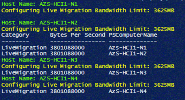
Procedure 12. Create Maximum Bandwidth Limit for Management vNIC
Note: This is an optional configuration item that limits the network bandwidth to the management vNIC. The management vNIC shares total bandwidth with the bandwidth allocated to tenant network traffic. The allocated tenant network traffic bandwidth is 50% of the total bandwidth. The following configuration example sets the maximum bandwidth limit 4Gb/s (10% of the tenant network traffic bandwidth) for the management vNIC. This value can be adjusted as needed.
$nodes = (Get-ClusterNode -Cluster $Cluster).Name
foreach ($node in $nodes) {
Invoke-Command $node -scriptblock {
$MgmtBandwidthLimit = "10000000"
write-host "Host Name:" $env:COMPUTERNAME -ForegroundColor Green
Write-Host "Configuring management vNIC maximum bandwidth Limit: $MgmtBandwidthLimit" -ForegroundColor Yellow
Set-VMNetworkAdapter -ManagementOS -Name "vManagement(mgmt_compute_storage)" -MaximumBandwidth $MgmtBandwidthLimit
Write-Host "Verifying management vNIC maximum bandwidth Limit" -ForegroundColor Yellow
(Get-VMNetworkAdapter -ManagementOS -Name "vManagement(mgmt_compute_storage)").BandwidthSetting | ft ParentAdapter, MaximumBandwidth
}
}

Procedure 13. Create the File Share for the Cluster Witness
Step 1. Run the following commands:
Note: These commands require the files share witness server to be a domain member. It’s recommended that the witness share is placed on a highly available scale out file server. The “-ContinuouslyAvailable” command option should be used when creating a share on a highly available scale out file server.
$FSW = “fsw01.ucs-spaces.lab”
$FSWDomain = “ucs-spaces.lab”
$ShareName = "FSW-AzS-HCI-M6-C1"
$SharePath = "C:\FileShareWitness\FSW-AzS-HCI-M6-C1"
Invoke-Command -ComputerName $FSW -ScriptBlock {
#Create Directory on File Share Witness
Write-Host "Creating directory on files share witness"
mkdir $Using:SharePath
#Create file share on the file share witness
Write-Host "Creating file share on file share witness"
new-smbshare -Name $Using:ShareName -Path $Using:SharePath -FullAccess “ucs-spaces.lab\Domain Admins", "ucs-spaces.lab\AzS-HCI-M6-C1$", "ucs-spaces.lab\AzS-HCI1-N1$”, "ucs-spaces.lab\AzS-HCI1-N2$”, "ucs-spaces.lab\AzS-HCI1-N3$”, "ucs-spaces.lab\AzS-HCI1-N4$”
#Verify file share on file share witness
Write-Host "Verifying file share on file share witness"
Get-SmbShare -Name $Using:ShareName | ft name,path -AutoSize
#Verify file share permissions on the file share witness
Write-Host "Verifing file share permissions on the file share witness"
Get-SmbShareAccess -Name $Using:ShareName | ft –AutoSize
#Set file level permissions on the file share directory that match the file share permissions
Write-Host "Setting file level permissions on the file share directory that match the file share permissions"
Set-SmbPathAcl -ShareName $Using:ShareName
#Verify file level permissions on the file share
Write-Host "Verifying file level permissions on the file share"
Get-Acl -Path $Using:SharePath | fl
}
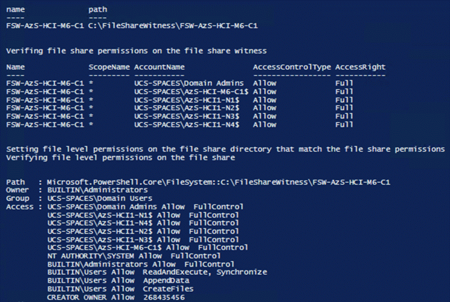
Procedure 14. Configure File Share Witness
Step 1. Run the following:
$Cluster = “AzS-HCI-M6-C1”
$FSW = “fsw01.ucs-spaces.lab”
$ShareName = "FSW-AzS-HCI-M6-C1"
Set-ClusterQuorum -Cluster $Cluster -FileShareWitness \\$FSW\$ShareName
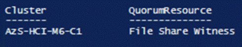
Procedure 15. Verify File Share Witness Path
Step 1. Run the following:
$Cluster = “AzS-HCI-M6-C1”
Get-ClusterResource -Cluster $Cluster -Name "File Share Witness" | Get-ClusterParameter -Name SharePath
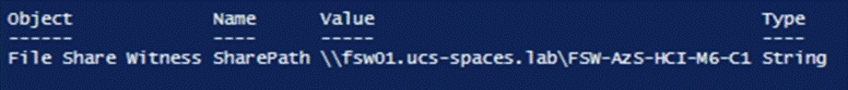
Procedure 16. Additional Cluster Quorum Witness Options
Note: Cloud Witness and none domain join files share witness can be implemented as alternate cluster witness options. Implementation details for these options can be found that the following links:
https://docs.microsoft.com/en-us/windows-server/failover-clustering/deploy-cloud-witness
Procedure 17. Configure Cluster-Aware Updating
Note: The Cluster-Aware Updating role will be installed after the cluster is created. The cluster-aware updating is a feature that automates downloading and installing Windows Server updates on all cluster nodes.
Please see the documentation at the following link for further Cluster-Aware Updating details: https://docs.microsoft.com/en-us/windows-server/failover-clustering/cluster-aware-updating
Step 1. Run the following commands to configure Cluster-Aware Updating:
$Cluster = “AzS-HCI-M6-C1"
Invoke-Command $Cluster -Credential $Creds -scriptblock {
write-host "Host Name:" $env:COMPUTERNAME -ForegroundColor Green
Write-Host " Enabling CredSSP" -ForegroundColor Yellow
$Void = Enable-WSManCredSSP -Role Server -Force
}
Invoke-Command $Cluster -Credential $Creds -authentication Credssp -scriptblock {
write-host "Host Name:" $env:COMPUTERNAME -ForegroundColor Green
Write-Host " Configuring Cluster-Aware Updating ... " -ForegroundColor Yellow
$ClusterName = (Get-cluster).Name
Add-CauClusterRole -ClusterName $ClusterName -DaysOfWeek Tuesday,Saturday -IntervalWeeks 3 -MaxFailedNodes 1 -MaxRetriesPerNode 2 -EnableFirewallRules -Force
Write-Host " Verifying Cluster-Aware Updating configuraiton " -ForegroundColor Yellow
Get-CauClusterRole -ClusterName $ClusterName | ft
Write-Host " Disabling CredSSP" -ForegroundColor Yellow
Disable-WSManCredSSP -Role Server
Write-Host " Verifying that CredSSP are disabled on target server..." -ForegroundColor Yellow
Get-WSManCredSSP
}
Note: This process might take several minutes.
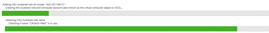
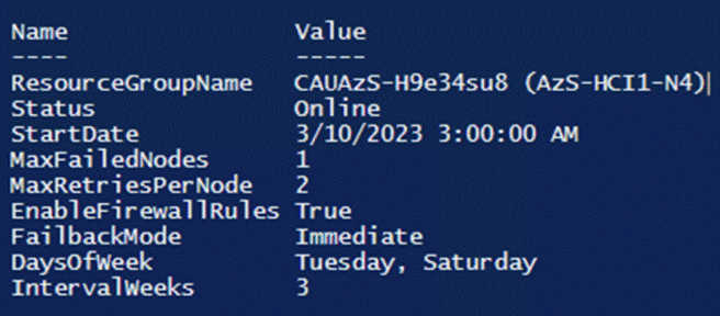
Procedure 18. Configure Kernel Soft Reboot for Cluster Aware Updating
Note: Kernel Soft Reboot reduces the time required to reboot a server by bypassing BIOS and firmware initiation. Kernel Soft Reboot works with Cluster Aware Updating for applying software updates. Kernel Soft Reboot cannot be used to the server when BIOS and firmware updates need to be applied.
Step 1. Run the following:
$Cluster = “AzS-HCI-M6-C1”
Invoke-Command $Cluster -Credential $Creds -scriptblock {
write-host "Host Name:" $env:COMPUTERNAME -ForegroundColor Green
Write-Host " Enabling CredSSP" -ForegroundColor Yellow
$Void = Enable-WSManCredSSP -Role Server -Force
}
Invoke-Command $Cluster -Credential $Creds -authentication Credssp -scriptblock {
write-host "Host Name:" $env:COMPUTERNAME -ForegroundColor Green
$ClusterName = (Get-cluster).Name
Write-Host " Configuring Kernel Soft Reboot for Cluster Aware Updating ... " -ForegroundColor Yellow
Get-Cluster -Name $ClusterName | Set-ClusterParameter -Name CauEnableSoftReboot -Value 1 -Create
Write-Host " Verifying Kernel Soft Reboot configuraiton " -ForegroundColor Yellow
Get-Cluster -Name $ClusterName | Get-ClusterParameter -Name CauEnableSoftReboot | ft Name, Value
Write-Host " Disabling CredSSP" -ForegroundColor Yellow
Disable-WSManCredSSP -Role Server
Write-Host " Verifying that CredSSP are disabled on target server..." -ForegroundColor Yellow
Get-WSManCredSSP
}
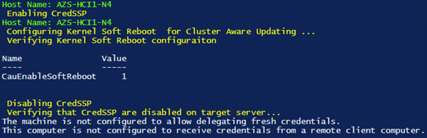
Configure Storage Spaces Direct
This subject contains the following procedures:
● Enable Storage Spaces Direct
● Verify the newly created Storage Pool, NVMe SSD Cache, and Storage Tiers
● Create a Virtual Disk with Mirror Resiliency by using the Performance Tier template
● Register the Azure Stack HCI Cluster with Azure
● Create a Virtual Machine with Failover Capability
Procedure 1. Enable Storage Spaces Direct
The following command automatically enables Storage Spaces Direct and configures the following:
● Create a pool: Creates a single large pool that has a name like “S2D on Cluster1”.
● Configures the Storage Spaces Direct caches: If there is more than one media (drive) type available for Storage Spaces Direct use, it enables the fastest as cache devices (read and write in most cases).
● Tiers: Creates 2 tiers as default tiers. One is called “Capacity” and the other called “Performance.” The cmdlet analyzes the devices and configures each tier with the mix of device types and resiliency.
$Cluster = “AzS-HCI-M6-C1"
Invoke-Command $Cluster -Credential $Creds -scriptblock {
write-host "Host Name:" $env:COMPUTERNAME -ForegroundColor Green
Write-Host " Enabling CredSSP" -ForegroundColor Yellow
$Void = Enable-WSManCredSSP -Role Server -Force
}
Invoke-Command $Cluster -Credential $Creds -authentication Credssp -scriptblock {
write-host "Host Name:" $env:COMPUTERNAME -ForegroundColor Green
$ClusterName = (Get-cluster).Name
Write-Host " Enabling Storage Spaces Direct " -ForegroundColor Yellow
Enable-ClusterStorageSpacesDirect -Confirm:$false
Write-Host " Disabling CredSSP" -ForegroundColor Yellow
Disable-WSManCredSSP -Role Server
Write-Host " Verifying that CredSSP are disabled on target server..." -ForegroundColor Yellow
Get-WSManCredSSP
}
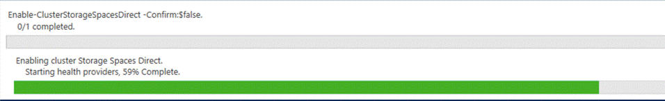
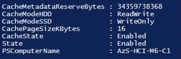
Procedure 2. Verify the newly created Storage Pool, NVMe SSD Cache, and Storage Tiers
Step 1. Run the following:
$Cluster = “AzS-HCI-M6-C1"
Invoke-Command $Cluster -Credential $Creds -scriptblock {
write-host "Host Name:" $env:COMPUTERNAME -ForegroundColor Green
Write-Host " Enabling CredSSP" -ForegroundColor Yellow
$Void = Enable-WSManCredSSP -Role Server -Force
}
Invoke-Command $Cluster -Credential $Creds -authentication Credssp -scriptblock {
write-host "Host Name:" $env:COMPUTERNAME -ForegroundColor Green
$ClusterName = (Get-cluster).Name
Write-Host " Verifying Storage Pools " -ForegroundColor Yellow
Get-StoragePool | ft friendlyname, OperationalStatus, HealthStatus, IsPrimordial, IsReadonly
Write-Host " Verifying NVMe SSD Cache Tier " -ForegroundColor Yellow
Get-PhysicalDisk | ? Usage -eq "Journal" | ft FriendlyName, CanPool, HealthStatus, Usage, Size
Write-Host " Verifying Storage Tier configuration " -ForegroundColor Yellow
Get-storagetier | ft FriendlyName, ResiliencySettingName, MediaType, NumberOfDataCopies, PhysicalDiskRedundancy
Write-Host " Disabling CredSSP" -ForegroundColor Yellow
Disable-WSManCredSSP -Role Server
Write-Host " Verifying that CredSSP are disabled on target server..." -ForegroundColor Yellow
Get-WSManCredSSP
}
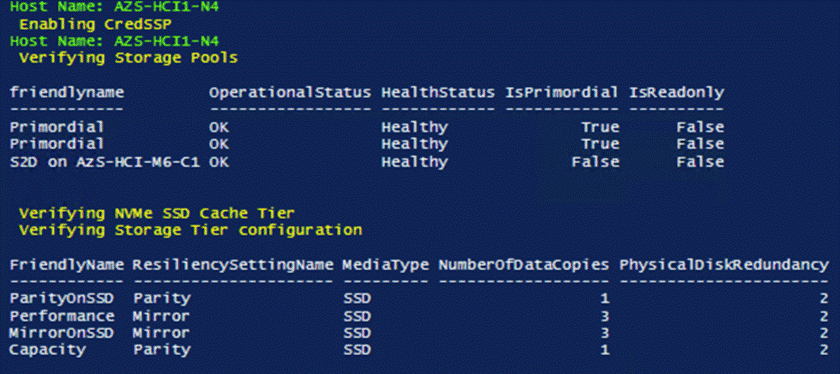
Procedure 3. Create a Virtual Disk with Mirror Resiliency by using the Performance Tier template
It is optimal to create a virtual disk in multiples that match the number of cluster nodes that will run virtual machines. For example, the number of virtual disks for cluster with 4 nodes should b 4, 8, 12, and so on.
Note: The following link contains Microsoft recommendations for volume capacity planning:
https://docs.microsoft.com/en-us/azure-stack/hci/concepts/plan-volumes
The New-Volume cmdlet simplifies deployments as it ties together a long list of operations that would otherwise have to be done in individual commands such as creating the virtual disk, partitioning, and formatting the virtual disk, adding the virtual disk to the cluster, and converting it into CSVFS.
Step 1. Run the following command to create the multiple times. Update the Virtual Disk friendly name and size as required:
$Cluster = “AzS-HCI-M6-C1”
Invoke-Command $Cluster -Credential $Creds -scriptblock {
write-host "Host Name:" $env:COMPUTERNAME -ForegroundColor Green
Write-Host " Enabling CredSSP" -ForegroundColor Yellow
$Void = Enable-WSManCredSSP -Role Server -Force
}
Invoke-Command $Cluster -Credential $Creds -authentication Credssp -scriptblock {
write-host "Host Name:" $env:COMPUTERNAME -ForegroundColor Green
$ClusterName = (Get-cluster).Name
Write-Host " Creating Virtual Disk " -ForegroundColor Yellow
New-Volume -StoragePoolFriendlyName “S2D*” -FriendlyName VDisk01 -FileSystem CSVFS_ReFS -ResiliencySettingName Mirror -Size 4TB
Write-Host " Disabling CredSSP" -ForegroundColor Yellow
Disable-WSManCredSSP -Role Server
Write-Host " Verifying that CredSSP are disabled on target server..." -ForegroundColor Yellow
Get-WSManCredSSP
}
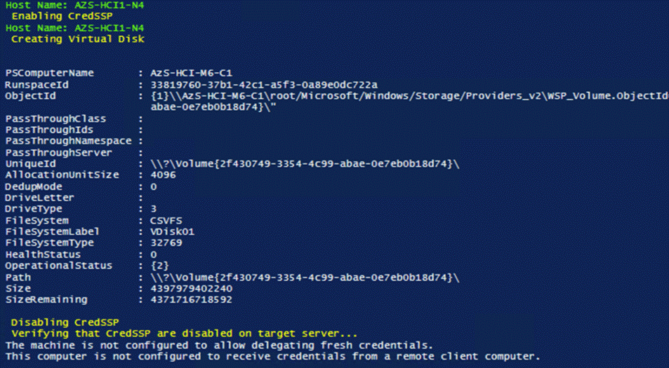
Step 2. The virtual disk status can be viewed by running the following command:
$cluster = "AzS-HCI-M6-C1"
Invoke-Command $cluster -scriptblock {Get-VirtualDisk}
Step 3. Run the following command to view the path of the new virtual disk:
$cluster = "AzS-HCI-M6-C1"
Invoke-Command $cluster -scriptblock {Get-ClusterSharedVolume | fl Name,SharedVolumeInfo,OwnerNode}
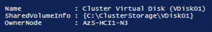
Note: The Cluster Shared Volume ownership can be realigned with the cluster nodes if desired. It is optimal when cluster virtual disk ownership id evenly distributed across the cluster nodes.
Procedure 4. Create Storage QoS Policy
Note: Storge QoS Policies limit the maximum IOPS that can be consumed by a virtual disk. These policies can prevent a “noisy neighbor” scenario where an individual virtual machine consumes an undesirable amount of storage IOPS and bandwidth, thus starving the available IOPS and bandwidth for other tenant virtual machines. The storage QoS policy is first created, and the policy ID is applied to a virtual disk (VHDX).
Step 1. The minimum and maximum IOPS values can be adjusted to as needed for the specific environment, by running the following command:
$Cluster = “AzS-HCI-M6-C1”
Invoke-Command $Cluster -Credential $Creds -scriptblock {
write-host "Host Name:" $env:COMPUTERNAME -ForegroundColor Green
Write-Host " Creating and verifying Storage Polices" -ForegroundColor Yellow
New-StorageQoSPolicy -Name Copper -MinimumIops 50 -MaximumIops 100 -PolicyType Dedicated
New-StorageQoSPolicy -Name Bronze -MinimumIops 100 -MaximumIops 250 -PolicyType Dedicated
New-StorageQoSPolicy -Name Silver -MinimumIops 200 -MaximumIops 500 -PolicyType Dedicated
New-StorageQoSPolicy -Name Gold -MinimumIops 500 -MaximumIops 5000 -PolicyType Dedicated
New-StorageQoSPolicy -Name Platinum -MinimumIops 1000 -MaximumIops 10000 -PolicyType Dedicated
Get-StorageQoSPolicy | ft Name,Status, MinimumIops,MaximumIops,MaximumIOBandwidth,PolicyID
}
Note: The Maximum IOPS value is in units of 8KB-normalized. IO larger than 8KB is treated as multiple normalize IOPS. For example, 64KB IO is treated as 8 normalized IOPS.
Procedure 5. Register the Azure Stack HCI Cluster with Azure
Note: Follow the documentation at the following link to register the cluster with the Azure subscription. The registration must be completed successfully in order to create virtual machines in the Azure Stack HCI cluster: https://docs.microsoft.com/en-us/azure-stack/hci/deploy/register-with-azure
Procedure 6. Create a Virtual Machine with Failover Capability
Note: The following script is an example of creating a virtual machine with failover capability. This example includes creation of a VHDX file for the virtual machine with an attached storage QoS policy:
$Cluster = “AzS-HCI-M6-C1”
Invoke-Command $Cluster -Credential $Creds -scriptblock {
write-host "Host Name:" $env:COMPUTERNAME -ForegroundColor Green
Write-Host " Enabling CredSSP" -ForegroundColor Yellow
$Void = Enable-WSManCredSSP -Role Server -Force
}
Invoke-Command $Cluster -Credential $Creds -authentication Credssp -scriptblock {
write-host "Host Name:" $env:COMPUTERNAME -ForegroundColor Green
$CSVPath = ((Get-ClusterSharedVolume).SharedVolumeInfo).FriendlyVolumeName
$VHDPath = "$CSVPath\VM01-Disk01.vhdx"
$VMSwitch = (Get-VMSwitch).Name
$VMName = "VM01"
$VMPath = "$CSVPath\VirtualMachines"
$VMMemoryCapacity = 8GB
Write-Host "Creating VHDX $VHDPath ..." -ForegroundColor Yellow
New-VHD -Path $CSVPath\VM01-Disk01.vhdx -Fixed -SizeBytes 100GB
Write-Host "Creating virtual machine $VMName with memory capacity $VMMemoryCapacity ... " -ForegroundColor Yellow
New-VM -Name $VMName -Path $VMPath -MemoryStartupBytes $VMMemoryCapacity -VHDPath $VHDPath -Generation 2 -SwitchName $VMSwitch
$BronzeStorageQoSPolicyID = (Get-StorageQosPolicy -Name Silver).PolicyId
Write-Host "Setting QoS Plicy for virtual machine $VMName ..." -ForegroundColor Yellow
Get-VM -VMName $VMName | Get-VMHardDiskDrive | Set-VMHardDiskDrive -QoSPolicyID $BronzeStorageQoSPolicyID
Write-Host "Clustering the virtual machine $VMName ..." -ForegroundColor Yellow
Get-VM -Name $VMName | Add-ClusterVirtualMachineRole -Name $VMName
Write-Host " Disabling CredSSP" -ForegroundColor Yellow
Disable-WSManCredSSP -Role Server
Write-Host " Verifying that CredSSP are disabled on target server..." -ForegroundColor Yellow
Get-WSManCredSSP
}
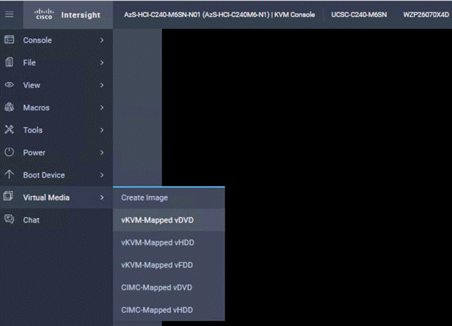
This chapter contains the following:
● Launch Server KVM Instance to Install the Operating System
● Locate Windows Driver Required for Cisco UCS C240 M6 Server
● Add Drivers and Windows Updates to a Windows Installation Image
● Install and Configure DHCP Server Feature
● Configure Bitlocker for System Volume
Cluster-Aware Updating: https://docs.microsoft.com/en-us/windows-server/failover-clustering/cluster-aware-updating
Active Memory Dump: https://techcommunity.microsoft.com/t5/failover-clustering/windows-server-2016-failover-cluster-troubleshooting/ba-p/372008
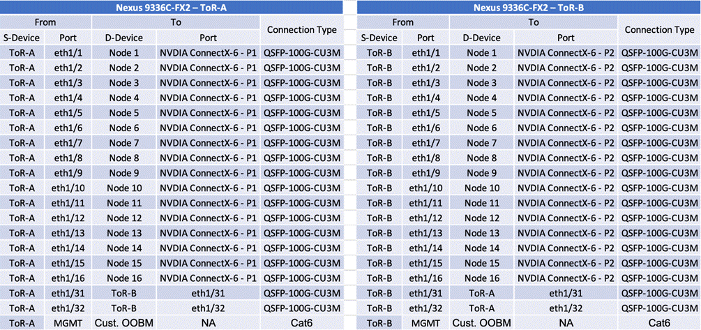
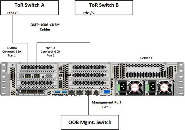
The required Widows features are as follows:
● Clustering
● Hyper-V Management
● Group Policy Management
● Bitlocker Recovery Password Viewer
● Active Directory Management Tools
#Install required management modules
Add-WindowsFeature -Name RSAT-Hyper-V-Tools,RSAT-ADDS-Tools, RSAT-Clustering, RSAT-Clustering-MgmtRSAT-Clustering-PowerShell, RSAT-Feature-Tools-BitLocker-BdeAducExt,GPMC -IncludeManagementTools
Install-Module AZ.ConnectedMachine -force
#Update download provider modules for downloading modules from PSGallery
Set-PSRepository -Name "PSGallery" -InstallationPolicy Trusted
Install-PackageProvider -Name NuGet -Force
Install-Module -Name PowershellGet -Force -Confirm:$false
#Close and restart the PowerShell Windows before proceeding
#Configure WinRM for remote management of nodes
winrm quickconfig
#Enable sending remote management commands to the cluster nodes
$nodes = ("AzS-HCI1-N1", " AzS-HCI1-N2", " AzS-HCI1-N3", " AzS-HCI1-N4")
Launch Server KVM Instance to Install the Operating System
Procedure 1. Install the OS by launching the Server KVM Instance
Install the Azur Stack HCI OS 22H2 using PXE boot or a vMedia mapped installation ISO. This section explains the steps to install OS using vMedia method. Installation of OS using PXE boot is out of the scope of this document.
Step 1. On the Server tab in Cisco Intersight, select Servers. From the list of options select Launch vKVM.
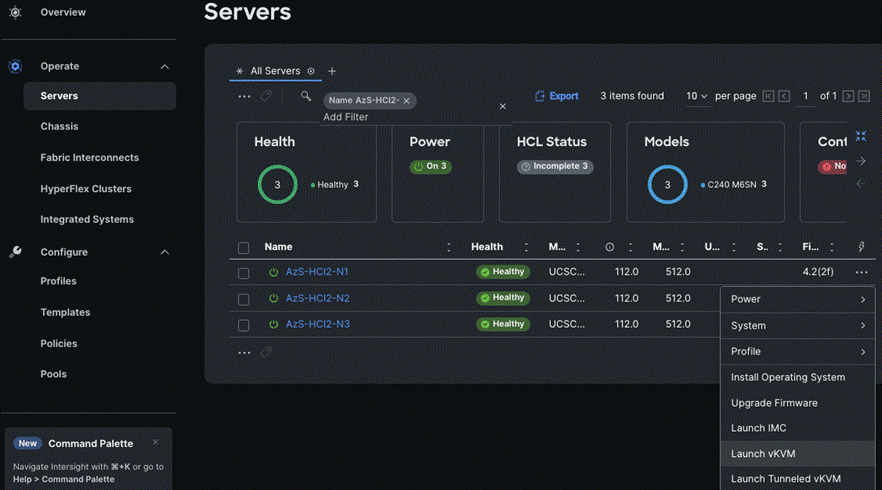
Step 2. On the left pane of KVM page, navigate down to Virtual Media and select vKVM-Mapped DVD.

Step 3. A Map Virtual Media – CD/DVD window displays, click Browse.
Step 4. Select the downloaded Azure Stack HCI OS 22H2 and click Map Drive.
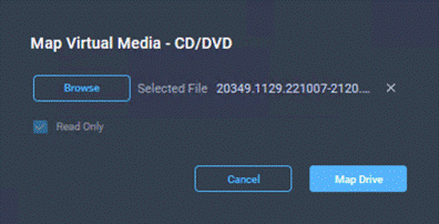
Step 5. Verify the file is selected by clicking Virtual Media.
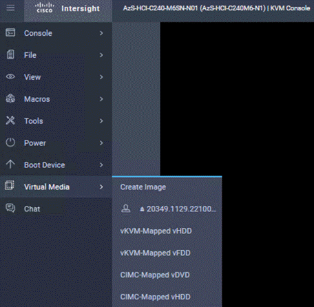
Step 6. Navigate to Power and click Power Cycle System to restart the server.
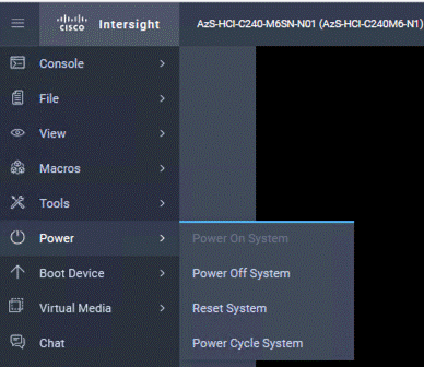
Step 7. During the POST, press F6 to launch Boot Menu.
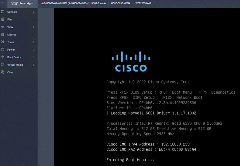
Step 8. In the Select boot device, select Cisco vKVM-Mapped vDVD and press Enter.
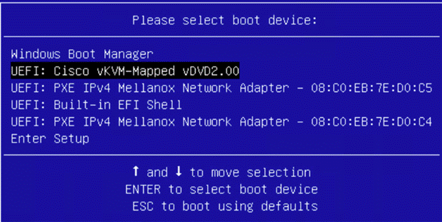
Step 9. Wait for Press any key to boot from CD or DVD on the screen and press any key to launch the OS installation.
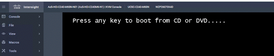
Step 10. The installation begins. Next, follow the interactive steps and complete the installation.
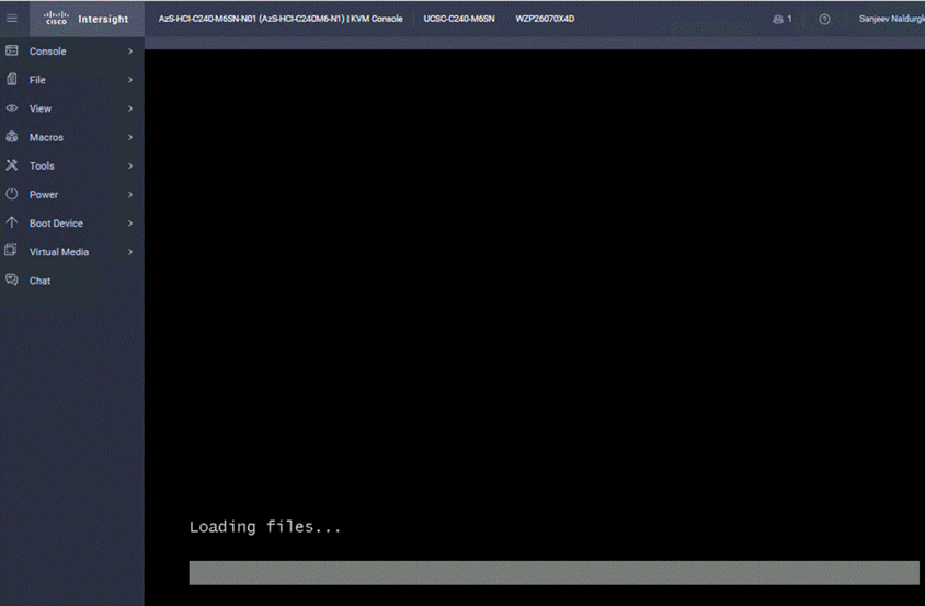
Locate Windows Driver Required for Cisco UCS C240 M6 Server
Post OS installation, download the relevant Windows driver image for the Cisco UCS Standalone Server software (4.2.3b) from the download portal Software Download - Cisco Systems and install the drivers for Chipset, Storage, and Network.
Mount the downloaded iso image for Windows drivers only.
Copy the following files from the mounted drive to a separate folder. Copy this folder with drivers to all the Cisco UCS C240 M6 servers.
.\ChipSet\Intel\ChipsetSoftware\10.1.18807.8279\SetupChipset.ex
.\Network\Mellanox\ConnectX4-5-6\W2K22\MLNX_WinOF2-3_0_50000_All_x64.exe
.\Storage\Intel\C600\W2K22\*.*
Intel Chipset Installation
Run the following command on all the nodes to install the chipset drivers. The system will restart automatically in couple of minutes after the chipset installation in unattended silent mode. Monitor and wait for system to restart.
SetupChipset.exe -silent
![]()
NVIDIA/Mellanox ConnectX-6 DX Driver Installation
Run the following command on all the nodes to install the drivers for NVIDIA (Mellanox) in unattended mode.
Unattended install
MLNX_WinOF2-[Driver/Version]_<revision_version>_All_-Arch.exe /S /v/qn
Unattended install with Logs
MLNX_WinOF2-[Driver/Version]_<revision_version>_All_-Arch.exe /S /v/qn /v”/l*vx [LogFile]"
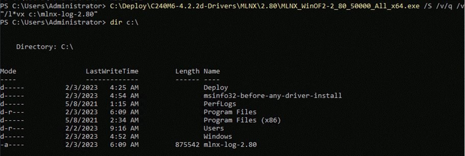
Alternatively, run the following command to extract only the driver files and use pnputil command to install the drivers:
MLNX_WinOF2-2_0_<revision_version>_All_x64.exe /a /vMT_DRIVERS_ONLY=1
Storage Drivers Install
Run the below command to install the Intel storage (MegaSR) drivers:
pnputil.exe /add-driver C:\Deploy\C240M6-4.2.3b-Drivers\Storage\Intel\C600\W2K22\*.inf /install
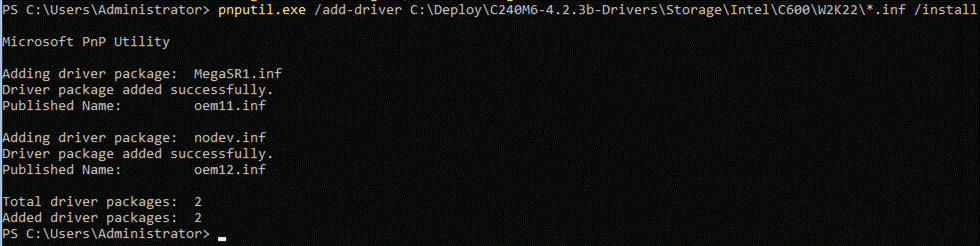
Note: All driers can be installed using PNPUtil.exe.
The following PNPUtile.exe example can be used to install drivers:
pnputil /add-driver C:\temp\drivers \*.inf
PNPUtil.exe documentation can be found at the following link: https://docs.microsoft.com/en-us/windows-hardware/drivers/devtest/pnputil
Add Drivers and Windows Updates to a Windows Installation Image
A Windows ISO image includes boot.wim and install.wim files that are used for installation. The following are the PowerShell cmdlets to inject drivers into these .wim files.
● Get-WindowsImage
https://docs.microsoft.com/en-us/powershell/module/dism/get-windowsimage?view=win10-ps
● Mount-WindowsImage
https://docs.microsoft.com/en-us/powershell/module/dism/mount-windowsimage?view=win10-ps
● Add-WindowsDriver
https://docs.microsoft.com/en-us/powershell/module/dism/add-windowsdriver?view=win10-ps
● Dismount-WindowsImage
https://docs.microsoft.com/en-us/powershell/module/dism/dismount-windowsimage?view=win10-ps
Procedure 1. Prepare Driver Injection Computer
Step 1. Copy contents of Windows Server 2019 ISO distribution ISO, including boot.wim and install.wim, to a computer disk that will be used to inject the drivers.
Example:
Destination path = C:\temp\Source-ISO
Step 2. Copy required drivers into a subdirectory on the server. Each driver should have its own subdirectory. Each driver should include a .sys, .inf, and a .cat file at minimum. Drivers cannot be in a zip file or exe file. Chipset drivers need to be extracted prior to injection.
Example:
Destination path: C:\temp\drivers
Step 3. Create a subdirectory for mounting the target image.
Example:
md C:\temp\offline
Procedure 2. Inject Drivers into boot.wim Images
Step 1. Identify available images in the boot file (there should be two).
Example:
Get-WindowsImage -ImagePath C:\temp\Source-ISO \boot.wim
Step 2. Identify the index for the index number of the image that needs drivers.
Step 3. Mount the target image.
Example:
Mount-WindowsImage -ImagePath C:\temp\Source-ISO \boot.wim -Index 2 -Path C:\temp\offline
Step 4. Add drivers to the mounted image. You only need to add the drivers for devices that need to be accessed during the preinstallation phase and are not in the Windows distribution. This may be the boot device drivers and network drivers.
Example:
Add-WindowsDriver -Path .\offline -Driver C:\temp\drivers\[NetworkDriver]
Add-WindowsDriver -Path .\offline -Driver C:\temp\drivers\[BootDeviceDriver]
Step 5. Save and dismount the image.
Example:
Dismount-WindowsImage -Path c:\temp\offline -save
Step 6. Repeat steps 1 – 5 for the other images in the boot.wim file if necessary.
Procedure 3. Inject Drivers into install.wim images
Step 1. Identify available images in the boot file (there should be two).
Example:
Get-WindowsImage -ImagePath C:\temp\Source-ISO\install.wim
Step 2. Identify the index for the index number of the image that needs drivers.
Step 3. Mount the target image.
Example:
Mount-WindowsImage -ImagePath C:\temp\Source-ISO\install.wim -Index 4 -Path C:\temp\offline
Step 4. Add drivers to the mounted image. You only need to add all required drivers.
Example:
Add-WindowsDriver -Path C:\temp \offline -Driver C:\temp \drivers -Recurse
Step 5. Save and dismount the image.
Example:
Dismount-WindowsImage -Path c:\temp\offline -save
Step 6. Repeat steps 1 – 5 for the other images in the install.wim file if necessary.
The updated install.wim and boot.wim can be copied to and PXE server that is used for deployment. WDS (Windows Deployment Service) is an example of a PXE server that can be used to deploy the Windows operating system.
Create an ISO image with Update .WIM Files
Incase a PXE server is unavailable for executing deployments, the operating system can be installed using and Windows installation ISO image. A new ISO image must be created with the updated .WIM installation files.
OSCDIMG.exe is a command line tool that can be used to create a new ISO installation image using the updated files. This tool is part of if the Automation Deployment Kit (ADK).
https://docs.microsoft.com/en-us/windows-hardware/get-started/adk-install
https://docs.microsoft.com/en-us/windows-hardware/manufacture/desktop/oscdimg-command-line-options
Example:
Oscdimg.exe -bC:\temp\Source-ISO\efi\microsoft\bootEfisys.bin -pEF -u1 -udfver102 C:\temp\Source-ISO C:\temp\Updated-Server2019.iso
Install and Configure DHCP Server Feature
Procedure 1. Run the following commands to install and configure the DHCP Server feature
Install-WindowsFeature -Name DHCP -IncludeManagementTools
netsh dhcp add securitygroups
Restart-Service dhcpserver
Add-DhcpServerv4Scope -name "HCI-Lab-P09-100.101.124.0" -StartRange 100.101.124.221 -EndRange 100.101.124.249 -SubnetMask 255.255.255.0 -State Active
Set-DhcpServerv4OptionValue -OptionID 3 -Value 100.101.124.1 -ScopeID 100.101.124.0
Set-DhcpServerv4OptionValue -OptionID 4 -Value 10.10.240.20 -ScopeID 100.101.124.0
Set-DhcpServerv4OptionValue -OptionID 42 -Value 10.10.240.20 -ScopeID 100.101.124.0
Set-DhcpServerv4OptionValue -OptionID 6 -Value 110.10.240.23 -ScopeID 100.101.124.0
Get-DhcpServerv4Scope -ScopeId 100.101.124.0
Get-DhcpServerv4OptionValue -ScopeId 100.101.124.0
#ScopeID 60 is required by WDS when DHCP is also running on the same server. ScopeID 60 is added as a DHCP a scope option when WDS is configured.
#OptionId 3 (Router)
#OptionId 4 (Time Server)
#OptionId 42 (NTP Server)
#OptionId 6 (DNS Server)
#Verify DHCP Scope
Get-DhcpServerv4Scope -ScopeId 100.101.124.0
#Verify DHCP Scope Option
Get-DhcpServerv4OptionValue -ScopeId 100.101.124.0
Configure Bitlocker for System Volume
Using Bitlocker to encrypt system volume is an optional procedure in the deployment. TPM will be the primary key protector for the encrypted volume. The TPM will automatically decrypt the system volume at boot time. A recovery password will be an additional key protector in case the TPM fails. The recovery password will be backed up and stored in Active Directory Domain Service.
Procedure 1. Verify that Secure Boot is Enabled
Step 1. Run the following:
$nodes = ("AzS-HCI-Host01", "AzS-HCI-Host02", "AzS-HCI-Host03", "AzS-HCI-Host04")
foreach ($node in $nodes) {
Invoke-Command $node -Credential $Creds -scriptblock {
write-host "Host Name:" $env:COMPUTERNAME
Write-Host "Checking Secure Boot Status " -ForegroundColor Yellow
Confirm-SecureBootUEFI
}
}
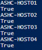
Procedure 2. Enable Bitlocker Group Policy
Note: A local group policy needs to be enabled. This local group policy allows the Recovery Password to be backed up to Active Directory Domain Service.
Step 1. Run the following:
$nodes = ("AzS-HCI-Host01", "AzS-HCI-Host02", "AzS-HCI-Host03", "AzS-HCI-Host04")
foreach ($node in $nodes) {
Invoke-Command $node -Credential $Creds -scriptblock {
write-host "Host Name:" $env:COMPUTERNAME -ForegroundColor Green
Write-Host "Cofiguring Bitlocker Registry settings to allow recovery password backup to AD... " -ForegroundColor Yellow
New-Item -Path HKLM:\SOFTWARE\Policies\Microsoft -Name FVE
New-ItemProperty -Path HKLM:\SOFTWARE\Policies\Microsoft\FVE -Name "OSRecovery" -Value ”1” -PropertyType DWORD
New-ItemProperty -Path HKLM:\SOFTWARE\Policies\Microsoft\FVE -Name "OSManageDRA" -Value ”1” -PropertyType DWORD
New-ItemProperty -Path HKLM:\SOFTWARE\Policies\Microsoft\FVE -Name "OSRecoveryPassword" -Value ”2” -PropertyType DWORD
New-ItemProperty -Path HKLM:\SOFTWARE\Policies\Microsoft\FVE -Name "OSRecoveryKey" -Value ”2” -PropertyType DWORD
New-ItemProperty -Path HKLM:\SOFTWARE\Policies\Microsoft\FVE -Name "OSHideRecoveryPage" -Value ”0” -PropertyType DWORD
New-ItemProperty -Path HKLM:\SOFTWARE\Policies\Microsoft\FVE -Name "OSActiveDirectoryBackup" -Value ”1” -PropertyType DWORD
New-ItemProperty -Path HKLM:\SOFTWARE\Policies\Microsoft\FVE -Name "OSActiveDirectoryInfoToStore" -Value ”1” -PropertyType DWORD
New-ItemProperty -Path HKLM:\SOFTWARE\Policies\Microsoft\FVE -Name "OSRequireActiveDirectoryBackup" -Value ”0” -PropertyType DWORD
Get-ItemProperty -path HKLM:\SOFTWARE\Policies\Microsoft\FVE -Name "OSRecovery"
Get-ItemProperty -path HKLM:\SOFTWARE\Policies\Microsoft\FVE -Name "OSManageDRA"
Get-ItemProperty -path HKLM:\SOFTWARE\Policies\Microsoft\FVE -Name "OSRecoveryPassword"
Get-ItemProperty -path HKLM:\SOFTWARE\Policies\Microsoft\FVE -Name "OSHideRecoveryPage"
Get-ItemProperty -path HKLM:\SOFTWARE\Policies\Microsoft\FVE -Name "OSActiveDirectoryBackup"
Get-ItemProperty -path HKLM:\SOFTWARE\Policies\Microsoft\FVE -Name "OSActiveDirectoryInfoToStore"
Get-ItemProperty -path HKLM:\SOFTWARE\Policies\Microsoft\FVE -Name "OSRequireActiveDirectoryBackup"
}
}
Procedure 3. Create and Backup Recovery Password
Note: Create the recover password key protector and back it up to Active Directory Domain Service.
Step 1. Run the following:
$nodes = ("AzS-HCI-Host01", "AzS-HCI-Host02", "AzS-HCI-Host03", "AzS-HCI-Host04")
foreach ($node in $nodes) {
Invoke-Command $node -Credential $Creds -scriptblock {
write-host "Host Name:" $env:COMPUTERNAME -ForegroundColor Green
Write-Host "Creating and Backing Up Recovery Key " -ForegroundColor Yellow
Add-BitLockerKeyProtector -MountPoint "C:" -RecoveryPasswordProtector
$KPID = ((Get-BitLockerVolume -MountPoint "C:").KeyProtector | ? KeyProtectorType -EQ "RecoveryPassword").KeyProtectorId
Backup-BitLockerKeyProtector -MountPoint "C:" -KeyProtectorId $KPID
}
}
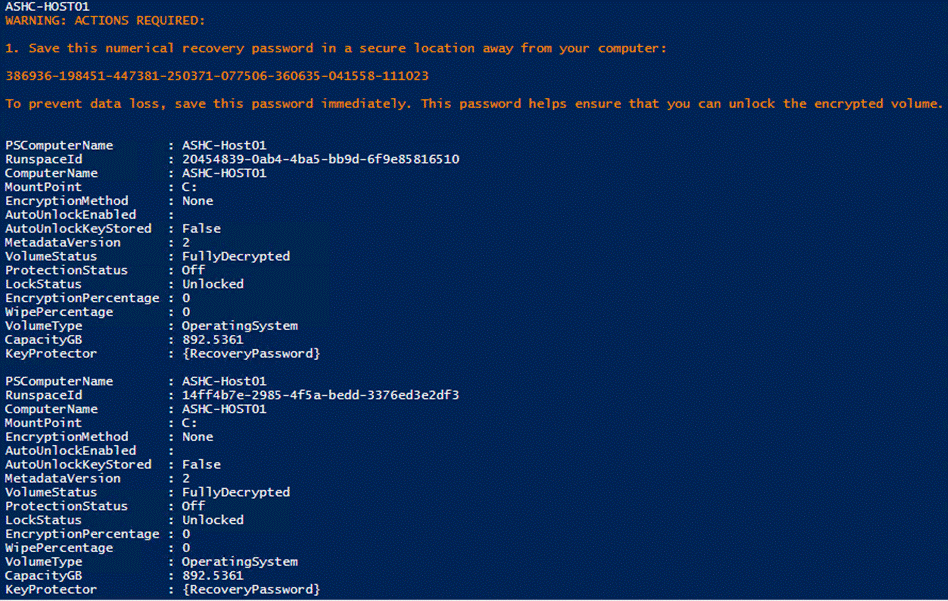
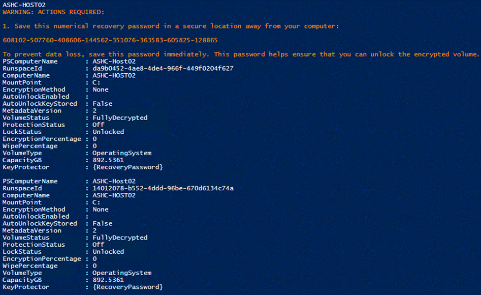
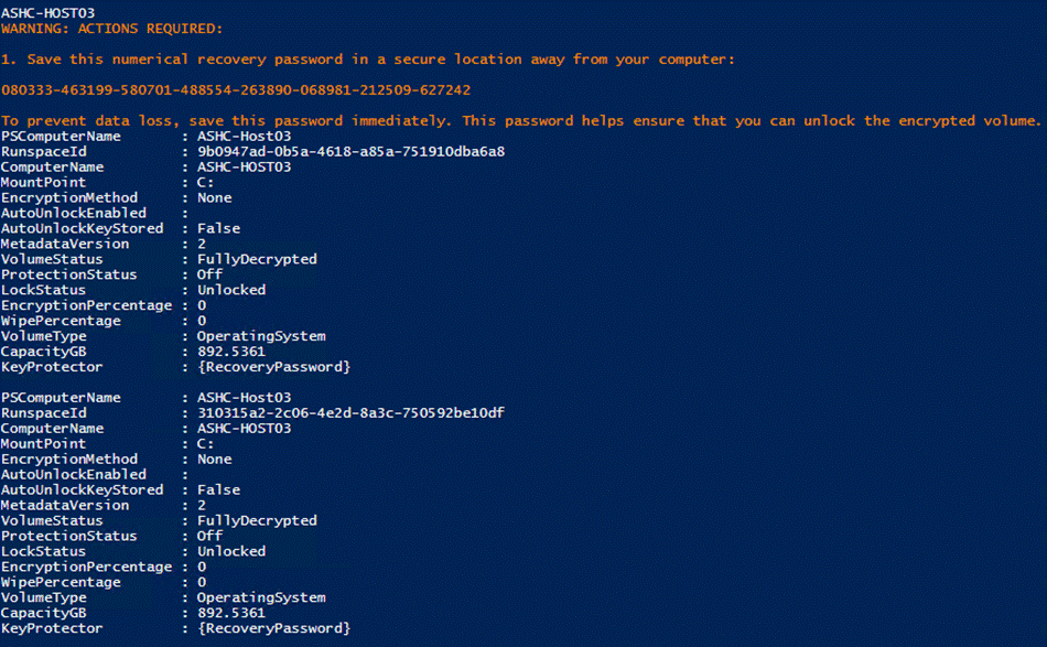
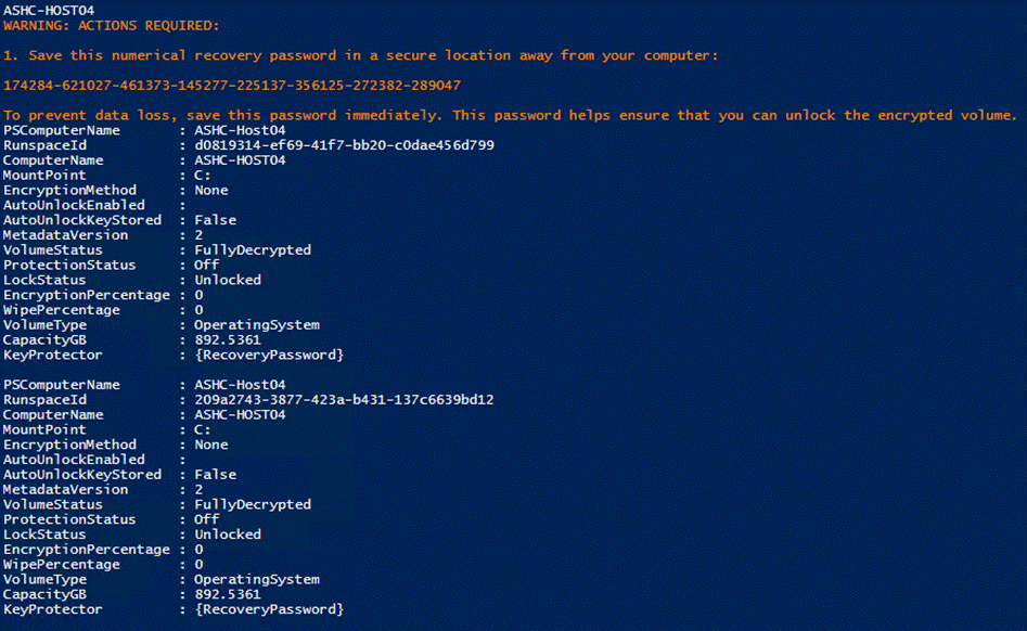
Procedure 4. Enable Bitlocker
Note: Enable Bitlocker for the system volume and add the TPM protector. Encryption of the system volume will not start until the server is rebooted.
Step 1. Run the following:
$nodes = ("AzS-HCI-Host01", "AzS-HCI-Host02", "AzS-HCI-Host03", "AzS-HCI-Host04")
foreach ($node in $nodes) {
Invoke-Command $node -Credential $Creds -scriptblock {
write-host "Host Name:" $env:COMPUTERNAME -ForegroundColor Green
Write-Host "Enabling Bitlocker Protection " -ForegroundColor Yellow
Enable-BitLocker -MountPoint "C:" -EncryptionMethod XtsAes256 -UsedSpaceOnly -TpmProtector
}
}
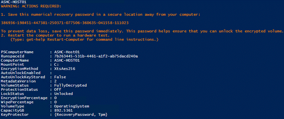
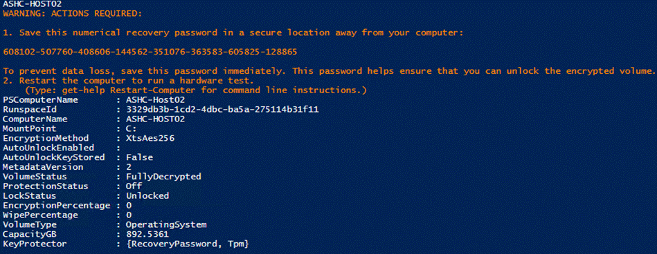
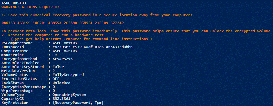
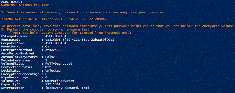
Procedure 5. Reboot Server to Enable Bitlocker for the System Volume
Note: Bitlocker will enable the when the server reboots. Bitlocker verifies that the key protectors are correctly configure. Volume encryption will take a few minutes to complete after the server reboots.
Step 1. Run the following:
$nodes = ("AzS-HCI-Host01", "AzS-HCI-Host02", "AzS-HCI-Host03", "AzS-HCI-Host04")
foreach ($node in $nodes) {
Invoke-Command $node -Credential $Creds -scriptblock {
write-host "Host Name:" $env:COMPUTERNAME -ForegroundColor Green
Write-Host "Restarting Host After Enabling Bitlocker Protection " -ForegroundColor Yellow
Restart-Computer -Force
}
}
Procedure 6. Verify Bitlocker Status
Note: Verify the Bitlocker Protection Status and Encryption Percentage.
Step 1. Run the following:
$nodes = ("AzS-HCI-Host01", "AzS-HCI-Host02", "AzS-HCI-Host03", "AzS-HCI-Host04")
foreach ($node in $nodes) {
Invoke-Command $node -Credential $Creds -scriptblock {
write-host "Host Name:" $env:COMPUTERNAME -ForegroundColor Green
Write-Host "Verifying Bitlocker Protection Status " -ForegroundColor Yellow
Get-BitlockerVolume -MountPoint "c:" | FT
}
}
Note: Bitlocker protection status will indicate “Off” until encryption reaches 100%.
Procedure 7. Verity Bitlocker Recovery Password Backup
Note: Bitlocker Recovery Password View provides the ability to read the backup of the recovery password that that is backed up to Active Directory Domain Services. This is an optional Windows feature that can be installed by running the following PowerShell command on a system that will be sued to read the password from Active Directly Domain Services.
Step 1. Add-WindowsFeature -Name RSAT-Feature-Tools-BitLocker-BdeAducExt
The following PowerShell scriptblock retrieves the Bitlocker password that is backed up to Active Directory:
$nodes = ("AzS-HCI-Host01", "AzS-HCI-Host02", "AzS-HCI-Host03", "AzS-HCI-Host04")
foreach ($node in $nodes) {
$objComputer = Get-ADComputer $node
write-host "Host Name:" $node -ForegroundColor Green
$Bitlocker_Objects = Get-ADObject -Filter {objectclass -eq 'msFVE-RecoveryInformation'} -SearchBase $objComputer.DistinguishedName -Properties 'msFVE-RecoveryPassword'
foreach ($Bitlocker_Object in $Bitlocker_Objects) {
Write-Host "Date, Time, and Password ID:" ($Bitlocker_Objects).Name
Write-Host "Recovery Password:" ($Bitlocker_Objects).'msFVE-RecoveryPassword' -ForegroundColor Cyan -Separator " "
Write-Host ""
}
}
Details on accessing the recovery password backup can be found at the following link. Recovery passwords backup should be verified as part of every deployment: https://docs.microsoft.com/en-us/windows/security/information-protection/bitlocker/bitlocker-use-bitlocker-recovery-password-viewer
Organizations using Bitlocker should be familiar with Bitlocker recovery procedures in case recovering access to a Bitlocker protected volume is required. The Microsoft guide to Bitlocker recovery can be found at the following link: https://docs.microsoft.com/en-us/windows/security/information-protection/bitlocker/bitlocker-recovery-guide-plan
ToR Switch Configuration Example
This section describes the ToR (Cisco Nexus 9336C-FX2) switches example configuration used for the deployment of this Azure Stack HCI solution. The Cisco Nexus switch configuration explains the basic L2 and L3 functionality and QoS configuration for the Azure Stack HCI solution environment used in the validation environment. The gateways required for this solution are hosted by the pair of Cisco Nexus switches, but the primary routing is passed onto an existing router that is upstream of the converged infrastructure. This upstream router will need to be aware of any networks created on the Cisco Nexus switches, but configuration of an upstream router is beyond the scope of this deployment guide.
Check NXOS Version
For Azure Stack HCI solution, the supported NXOS version is 10.3(2)F or later and the supported Cisco Nexus switches are listed here: https://learn.microsoft.com/en-us/azure-stack/hci/concepts/physical-network-requirements?tabs=Cisco%2C22H2reqs
| ToR-A |
ToR-B |
| show version | include 'NXOS|Chassis' NXOS: version 10.3(2) [Feature Release] NXOS image file is: bootflash:///nxos64-cs.10.3.2.F.bin cisco Nexus9000 C9336C-FX2 Chassis |
show version | include 'NXOS|Chassis' NXOS: version 10.3(2) [Feature Release] NXOS image file is: bootflash:///nxos64-cs.10.3.2.F.bin cisco Nexus9000 C9336C-FX2 Chassis |
Enable Features
Some of the key NX-OS features implemented for this solution are:
● Feature interface-vlan – Allows for VLAN IP interfaces to be configured within the switch as gateways.
● Feature HSRP – Allows for Hot Standby Routing Protocol configuration for high availability.
● Feature LACP – Allows for the utilization of Link Aggregation Control Protocol (802.3ad) by the port channels configured on the switch.
● Feature vPC – Virtual Port-Channel (vPC) presents the two Nexus switches as a single “logical” port channel to the connecting upstream or downstream device.
● Feature LLDP - Link Layer Discovery Protocol (LLDP), a vendor-neutral device discovery protocol, allows the discovery of both Cisco devices and devices from other sources.
● Feature NX-API – NX-API improves the accessibility of CLI by making it available outside of the switch by using HTTP/HTTPS. This feature helps with configuring the Cisco Nexus switch remotely using the automation framework.
● Feature UDLD – Enables unidirectional link detection for various interfaces.
● Feature DHCP - Allows for the configuration of DHCP relay agent, DHCP snooping, or any of the features that depend on DHCP
● Feature scp-server - Enables the SCP (Secure Copy) server on the Cisco NX-OS device in order to copy files and from a remote device.
| ToR-A |
ToR-B |
| feature nxapi feature scp-server cfs eth distribute feature bgp feature udld feature interface-vlan feature hsrp feature lacp feature dhcp feature vpc feature lldp |
feature nxapi feature scp-server cfs eth distribute feature bgp feature udld feature interface-vlan feature hsrp feature lacp feature dhcp feature vpc feature lldp |
Configure VLANs
The table below provides the VLANs created for different traffics used in this solution.
| ToR-A |
ToR-B |
| vlan 2 name Reserved_Port_Ethernet vlan 101 name Tenant vlan 107 name StorageA vlan 126 name Management vlan 207 name StorageB |
vlan 2 name Reserved_Port_Ethernet vlan 101 name Tenant vlan 107 name StorageA vlan 126 name Management vlan 207 name StorageB |
Create Hot Standby Router Protocol (HSRP) Switched Virtual Interfaces (SVI)
These interfaces can be considered optional if the subnets of the VLANs used within the environment are managed entirely by an upstream switch, but if that is the case, all managed VLANs will need to be carried up through the vPC to the Upstream switches.
Routing between the SVIs is directly connected between them as they reside in the same Virtual Routing and Forwarding in-stance (VRF), and traffic set to enter and exit the VRF will traverse the default gateway set for the switches.
| ToR-A |
ToR-B |
| interface Vlan2 description Unused_Ports mtu 9216 interface Vlan101 description Tenant network no shutdown mtu 9216 no ip redirects ip address 192.168.101.2/24 ip directed-broadcast no ipv6 redirects hsrp version 2 hsrp 101 priority 150 forwarding-threshold lower 1 upper 150 ip 192.168.101.1 ip dhcp relay address 192.168.0.10
interface Vlan126 description Management Network no shutdown mtu 9216 no ip redirects ip address 192.168.126.2/26 ip directed-broadcast no ipv6 redirects hsrp version 2 hsrp 126 priority 150 forwarding-threshold lower 1 upper 150 ip 192.168.126.1 ip dhcp relay address 192.168.0.10
interface Vlan200 description P2P_TOR1-ibgp-1_To_TOR2-ibgp-1 no shutdown mtu 9216 no ip redirects ip address 192.168.200.45/30 no ipv6 redirects |
interface Vlan2 description Unused_Ports mtu 9216 interface Vlan101 description Tenant network no shutdown mtu 9216 no ip redirects ip address 192.168.101.3/24 ip directed-broadcast no ipv6 redirects hsrp version 2 hsrp 101 priority 140 forwarding-threshold lower 1 upper 140 ip 192.168.101.1 ip dhcp relay address 192.168.0.10
interface Vlan126 description Management Network no shutdown mtu 9216 no ip redirects ip address 192.168.126.3/26 ip directed-broadcast no ipv6 redirects hsrp version 2 hsrp 126 priority 140 forwarding-threshold lower 1 upper 140 ip 192.168.126.1 ip dhcp relay address 192.168.0.10
interface Vlan200 description P2P_TOR1-ibgp-1_To_TOR2-ibgp-1 no shutdown mtu 9216 no ip redirects ip address 192.168.200.46/30 no ipv6 redirects |
Create the vPC Domain
Create a vPC domain ID with a unique number (from 1 -1000) and configure the role priority and peer-keepalive on both the switches. The vPC domain ID is same on both switches and this will handle the vPC settings specified within the switches. Note that the commands for role priority value and peer-keepalive varies slightly on both switches.
| ToR-A |
ToR-B |
| interface mgmt0 vrf member management ip address 192.168.0.24/24
vpc domain 120 peer-switch role priority 10 peer-keepalive destination 192.168.0.25 source 192.168.0.24 delay restore 150 peer-gateway layer3 peer-router auto-recovery |
interface mgmt0 vrf member management ip address 192.168.0.25/24
vpc domain 120 peer-switch role priority 20 peer-keepalive destination 192.168.0.24 source 192.168.0.25 delay restore 150 peer-gateway layer3 peer-router auto-recovery |
On each switch, configure the Port Channel member interfaces that will be part of the vPC Peer Link and configure the vPC Peer Link:
| ToR-A |
ToR-B |
| interface port-channel10 description vPC Peer-Link ● switchport mode trunk switchport trunk allowed vlan 101,107,126,200,207 spanning-tree port type network service-policy type qos input AzS_HCI_QoS vpc peer-link |
interface port-channel10 description vPC Peer-Link switchport mode trunk switchport trunk allowed vlan 101,107,126,200,207 spanning-tree port type network service-policy type qos input AzS_HCI_QoS vpc peer-link |
QoS Configuration on ToR Switches (Cisco Nexus 9300 series switches)
This procedure explains the QoS configuration example for supporting RoCE (RDMA over Converged Ethernet) traffic on the ToR switches.
Using Cisco Modular Quality of Service Command Line Interface (MQC), you can define and configure QOS policies by following these steps:
1. Define a particular class of traffic.
2. After creating class-map, we put them in to a policy-map, where we mark (using bandwidth, policing, shaping, etc) the traffic.
3. Use a service-policy command to apply that p-map to an interface in inbound or outbound direction.
Note: The QoS configuration in the host OS should match the QoS configuration performed in the Network switch (ToR) configuration
Create class-map type QoS and match based on CoS Value
In the following example, RDMA (for storage traffic) and CLUSTER-COMM (for cluster heartbeat traffic) traffic classes are defined and matched with layer 2 CoS 4 and CoS 5 respectively for classification.
| ToR-A |
ToR-B |
| class-map type qos match-all RDMA match cos 4 class-map type qos match-all CLUSTER-COMM match cos 5 |
class-map type qos match-all RDMA match cos 4 class-map type qos match-all CLUSTER-COMM match cos 5 |
Create policy-map type QoS and Set qos-group and add/or Policing Rule
A policy-map named AzS_HCI_QoS is created and referenced to RDMA and CLUSTER-COMM class-maps and set the qos-group accordingly as shown in the following example.
| ToR-A |
ToR-B |
| policy-map type qos AzS_HCI_QoS class RDMA set qos-group 4 class CLUSTER-COMM set qos-group 5 |
policy-map type qos AzS_HCI_QoS class RDMA set qos-group 4 class CLUSTER-COMM set qos-group 5 |
Attach policy-map type QoS as input to an Interface
The policy-map created in the previous step is now applied to interfaces port-channel 10 and interfaces ethernet 1/1-4, where all Azure Stack HCI cluster nodes are connected.
| ToR-A |
ToR-B |
| interface port-channel10 service-policy type qos input AzS_HCI_QoS
interface Ethernet1/1 service-policy type qos input AzS_HCI_QoS
interface Ethernet1/2 service-policy type qos input AzS_HCI_QoS
interface Ethernet1/3 service-policy type qos input AzS_HCI_QoS
interface Ethernet1/4 service-policy type qos input AzS_HCI_QoS |
interface port-channel10 service-policy type qos input AzS_HCI_QoS
interface Ethernet1/1 service-policy type qos input AzS_HCI_QoS
interface Ethernet1/2 service-policy type qos input AzS_HCI_QoS
interface Ethernet1/3 service-policy type qos input AzS_HCI_QoS
interface Ethernet1/4 service-policy type qos input AzS_HCI_QoS |
Create class-map type network-qos and match based on qos-group Value
The network QoS policy defines the characteristics of QoS properties network wide.
Two class-map type network-qos named RDMA_CL_Map_NetQoS and Cluster-Comm_CL_Map_NetQoS are created and matched with qos-group 4 and qos-group 5, respectively.
| ToR-A |
ToR-B |
| class-map type network-qos RDMA_CL_Map_NetQos match qos-group 4 class-map type network-qos Cluster- Comm_CL_Map_NetQos match qos-group 5 |
class-map type network-qos RDMA_CL_Map_NetQos match qos-group 4 class-map type network-qos Cluster-Comm_CL_Map_NetQos match qos-group 5 |
Create policy-map type network-qos and Define Actions
In this example, the QoS network policy created to set Jumbo MTU for both traffic classes and no-drop (pause) to only RoCE traffic. During congestion, PFC sends a pause frame that indicates which CoS values needs to be paused This network-qos policy is then applied to the system.
| ToR-A |
ToR-B |
| policy-map type network-qos QOS_NETWORK class type network-qos RDMA_CL_Map_NetQos pause pfc-cos 4 mtu 9216 class type network-qos Cluster-Comm_CL_Map_NetQos mtu 9216 class type network-qos class-default mtu 9216 system qos service-policy type network-qos QOS_NETWORK |
policy-map type network-qos QOS_NETWORK class type network-qos RDMA_CL_Map_NetQos pause pfc-cos 4 mtu 9216 class type network-qos Cluster-Comm_CL_Map_NetQos mtu 9216 class type network-qos class-default mtu 9216 system qos service-policy type network-qos QOS_NETWORK |
Note: For the drop and no drop configuration, you also need to enable PFC per port.
Create policy-map type queuing referencing with the system-defined class-map type queuing and create actions
A policy map with minimum bandwidth percentage guarantee is specified to traffic class in periods of congestion - 50% is allocated to RDMA (storage) traffic, 49% is allocated to management and compute traffic and 1% is allocated to cluster heartbeat traffic.
Weighted random early detection (WRED) with minimum and maximum thresholds is also set to drop packets when the configured thresholds are exceeded. WRED configured with ECN (explicit congestion notification) marks packets instead of dropping them when the average queue length exceeds a specific threshold value. With WRED ECN feature, end hosts use this marking as signal that the network is congested to slow down sending packets.
| ToR-A |
ToR-B |
| policy-map type queuing QOS_EGRESS_PORT class type queuing c-out-8q-q-default bandwidth remaining percent 49 class type queuing c-out-8q-q1 bandwidth remaining percent 0 class type queuing c-out-8q-q2 bandwidth remaining percent 0 class type queuing c-out-8q-q3 bandwidth remaining percent 0 class type queuing c-out-8q-q4 bandwidth remaining percent 50 random-detect minimum-threshold 300 kbytes maximum-threshold 300 kbytes drop-probability 100 weight 0 ecn class type queuing c-out-8q-q5 bandwidth percent 1 class type queuing c-out-8q-q6 bandwidth remaining percent 0 class type queuing c-out-8q-q7 bandwidth remaining percent 0 system qos service-policy type queuing output QOS_EGRESS_PORT |
policy-map type queuing QOS_EGRESS_PORT class type queuing c-out-8q-q-default bandwidth remaining percent 49 class type queuing c-out-8q-q1 bandwidth remaining percent 0 class type queuing c-out-8q-q2 bandwidth remaining percent 0 class type queuing c-out-8q-q3 bandwidth remaining percent 0 class type queuing c-out-8q-q4 bandwidth remaining percent 50 random-detect minimum-threshold 300 kbytes maximum-threshold 300 kbytes drop-probability 100 weight 0 ecn class type queuing c-out-8q-q5 bandwidth percent 1 class type queuing c-out-8q-q6 bandwidth remaining percent 0 class type queuing c-out-8q-q7 bandwidth remaining percent 0 system qos service-policy type queuing output QOS_EGRESS_PORT |
Attach policy-map queuing to interfaces
The example below shows policy-map queuing and priority-flow-control on are applied to ethernet 1/1-4 interfaces. Azure Stack HCI cluster nodes are connected to these interfaces.
| ToR-A |
ToR-B |
| interface Ethernet1/1 priority-flow-control mode on service-policy type queuing output QOS_EGRESS_PORT
interface Ethernet1/2 priority-flow-control mode on service-policy type queuing output QOS_EGRESS_PORT
interface Ethernet1/3 priority-flow-control mode on service-policy type queuing output QOS_EGRESS_PORT
interface Ethernet1/4 priority-flow-control mode on service-policy type queuing output QOS_EGRESS_PORT |
interface Ethernet1/1 priority-flow-control mode on service-policy type queuing output QOS_EGRESS_PORT
interface Ethernet1/2 priority-flow-control mode on service-policy type queuing output QOS_EGRESS_PORT
interface Ethernet1/3 priority-flow-control mode on service-policy type queuing output QOS_EGRESS_PORT
interface Ethernet1/4 priority-flow-control mode on service-policy type queuing output QOS_EGRESS_PORT |
The example below shows the full running-configuration of both ToR switches used for this deployment.
| ToR-A |
ToR-B |
| switchname AzS-HCI-ToR1 class-map type network-qos RDMA_CL_Map_NetQos match qos-group 4 class-map type network-qos Cluster-Comm_CL_Map_NetQos match qos-group 5 policy-map type network-qos QOS_NETWORK class type network-qos RDMA_CL_Map_NetQos pause pfc-cos 4 mtu 9216 class type network-qos Cluster-Comm_CL_Map_NetQos mtu 9216 class type network-qos class-default mtu 9216 vdc AzS-HCI-ToR1 id 1 limit-resource vlan minimum 16 maximum 4094 limit-resource vrf minimum 2 maximum 4097 limit-resource port-channel minimum 0 maximum 511 limit-resource m4route-mem minimum 58 maximum 58 limit-resource m6route-mem minimum 8 maximum 8
feature nxapi feature scp-server cfs eth distribute feature bgp feature udld feature interface-vlan feature hsrp feature lacp feature dhcp feature vpc feature lldp
mac address-table aging-time 1510
ip domain-lookup spanning-tree mode mst class-map type qos match-all RDMA match cos 4 class-map type qos match-all CLUSTER-COMM match cos 5 policy-map type qos AzS_HCI_QoS class RDMA set qos-group 4 class CLUSTER-COMM set qos-group 5 policy-map type queuing QOS_EGRESS_PORT class type queuing c-out-8q-q-default bandwidth remaining percent 49 class type queuing c-out-8q-q1 bandwidth remaining percent 0 class type queuing c-out-8q-q2 bandwidth remaining percent 0 class type queuing c-out-8q-q3 bandwidth remaining percent 0 class type queuing c-out-8q-q4 bandwidth remaining percent 50 random-detect minimum-threshold 300 kbytes maximum-threshold 300 kbytes drop-probability 100 weight 0 ecn class type queuing c-out-8q-q5 bandwidth percent 1 class type queuing c-out-8q-q6 bandwidth remaining percent 0 class type queuing c-out-8q-q7 bandwidth remaining percent 0 system qos service-policy type queuing output QOS_EGRESS_PORT service-policy type network-qos QOS_NETWORK copp profile strict snmp-server user admin network-admin auth md5 0x743ead09954eb506ae83f49f45f2db95 priv des 0x743ead09954eb 506ae83f49f45f2db95 localizedkey rmon event 1 description FATAL(1) owner PMON@FATAL rmon event 2 description CRITICAL(2) owner PMON@CRITICAL rmon event 3 description ERROR(3) owner PMON@ERROR rmon event 4 description WARNING(4) owner PMON@WARNING rmon event 5 description INFORMATION(5) owner PMON@INFO ntp server 72.163.32.44 use-vrf management system default switchport
vlan 1-2,101,107,126,200,207 vlan 2 name Reserved_Port_Ethernet vlan 101 name Tenant vlan 107 name StorageA vlan 126 name Management vlan 200 name iBGP-Link vlan 207 name StorageB
spanning-tree port type edge bpduguard default spanning-tree port type edge bpdufilter default spanning-tree port type network default service dhcp ip dhcp relay ipv6 dhcp relay vrf context management ip route 0.0.0.0/0 192.168.0.1 congestion-control random-detect forward-nonecn vpc domain 120 peer-switch role priority 10 peer-keepalive destination 192.168.0.25 source 192.168.0.24 delay restore 150 peer-gateway layer3 peer-router auto-recovery
interface Vlan1 no ip redirects no ipv6 redirects
interface Vlan2 description Unused_Ports mtu 9216
interface Vlan101 description Tenant network no shutdown mtu 9216 no ip redirects ip address 192.168.101.2/24 ip directed-broadcast no ipv6 redirects hsrp version 2 hsrp 101 priority 150 forwarding-threshold lower 1 upper 150 ip 192.168.101.1 ip dhcp relay address 192.168.0.10
interface Vlan126 description Management Network no shutdown mtu 9216 no ip redirects ip address 192.168.126.2/26 ip directed-broadcast no ipv6 redirects hsrp version 2 hsrp 126 priority 150 forwarding-threshold lower 1 upper 150 ip 192.168.126.1 ip dhcp relay address 192.168.0.10
interface Vlan200 description P2P_TOR1-ibgp-1_To_TOR2-ibgp-1 no shutdown mtu 9216 no ip redirects ip address 192.168.200.45/30 no ipv6 redirects
interface port-channel10 description vPC Peer-Link switchport mode trunk switchport trunk allowed vlan 101,107,126,200,207 spanning-tree port type network service-policy type qos input AzS_HCI_QoS vpc peer-link
interface Ethernet1/1 description AzS-HCI Fabric-A NIC Port switchport mode trunk switchport trunk native vlan 126 switchport trunk allowed vlan 101,107,126 priority-flow-control mode on spanning-tree port type edge trunk mtu 9216 service-policy type qos input AzS_HCI_QoS service-policy type queuing output QOS_EGRESS_PORT no shutdown
interface Ethernet1/2 description AzS-HCI Fabric-A NIC Port switchport mode trunk switchport trunk native vlan 126 switchport trunk allowed vlan 101,107,126 priority-flow-control mode on spanning-tree port type edge trunk mtu 9216 service-policy type qos input AzS_HCI_QoS service-policy type queuing output QOS_EGRESS_PORT no shutdown
interface Ethernet1/3 description AzS-HCI Fabric-A NIC Port switchport mode trunk switchport trunk native vlan 126 switchport trunk allowed vlan 101,107,126 priority-flow-control mode on spanning-tree port type edge trunk mtu 9216 service-policy type qos input AzS_HCI_QoS service-policy type queuing output QOS_EGRESS_PORT no shutdown
interface Ethernet1/4 description AzS-HCI Fabric-A NIC Port switchport mode trunk switchport trunk native vlan 126 switchport trunk allowed vlan 101,107,126 priority-flow-control mode on spanning-tree port type edge trunk mtu 9216 service-policy type qos input AzS_HCI_QoS service-policy type queuing output QOS_EGRESS_PORT no shutdown
interface Ethernet1/5
interface Ethernet1/6
interface Ethernet1/7
interface Ethernet1/8
interface Ethernet1/9
interface Ethernet1/10
interface Ethernet1/11
interface Ethernet1/12
interface Ethernet1/13
interface Ethernet1/14
interface Ethernet1/15
interface Ethernet1/16
interface Ethernet1/17
interface Ethernet1/18
interface Ethernet1/19
interface Ethernet1/20
interface Ethernet1/21
interface Ethernet1/22
interface Ethernet1/23
interface Ethernet1/24
interface Ethernet1/25
interface Ethernet1/26
interface Ethernet1/27
interface Ethernet1/28
interface Ethernet1/29
interface Ethernet1/30
interface Ethernet1/31 description VPC Peer to ToR-B:/1/31 switchport mode trunk switchport trunk allowed vlan 101,107,126,200,207 channel-group 10 mode active no shutdown
interface Ethernet1/32 description VPC Peer to ToR-B:/1/32 switchport mode trunk switchport trunk allowed vlan 101,107,126,200,207 channel-group 10 mode active no shutdown
interface Ethernet1/33 description P2P_Boarder1_To_ToR1 no switchport mtu 9216 ip address 192.168.200.49/30 no shutdown
interface Ethernet1/34 description P2P_Boarder2_To_ToR1 no switchport mtu 9216 ip address 192.168.200.53/30 no shutdown
interface Ethernet1/35
interface Ethernet1/36
interface mgmt0 vrf member management ip address 192.168.0.24/24
interface loopback0 description INFRA:Loopback_/ToR1:AzS-HCI-TOR-1:192.168.200.41 ip address 192.168.200.41/32 line console line vty boot nxos bootflash:/nxos64-cs.10.3.2.F.bin router bgp 64911 router-id 192.168.200.41 bestpath as-path multipath-relax log-neighbor-changes address-family ipv4 unicast network 192.168.101.0/24 network 192.168.126.0/26 network 192.168.200.41/32 network 192.168.200.44/30 network 192.168.200.56/30 network 192.168.200.60/30 maximum-paths 8 maximum-paths ibgp 8 template peer Border1-64821 remote-as 64821 address-family ipv4 unicast maximum-prefix 12000 warning-only template peer Border2-64821 remote-as 64821 address-family ipv4 unicast maximum-prefix 12000 warning-only template peer iBGPPeer-64911 remote-as 64911 address-family ipv4 unicast maximum-prefix 12000 warning-only neighbor 192.168.200.46 inherit peer iBGPPeer-64911 description 64811:P2P_TOR1-ibgp-1_To_TOR2-ibgp-1:192.168.200.46 neighbor 192.168.200.50 inherit peer Border1-64821 description 64821:P2P_Boarder1_To_ToR1:192.168.200.50 address-family ipv4 unicast prefix-list ExternalPrefix in prefix-list ExternalPrefix out neighbor 192.168.200.54 inherit peer Border2-64821 description 64821:P2P_Boarder2_To_ToR1:192.168.200.54 address-family ipv4 unicast prefix-list ExternalPrefix in prefix-list ExternalPrefix out neighbor 192.168.101.0/24 inherit peer iBGPPeer-64911 description iBGPPeer-64911-Tenant:192.168.101.0 neighbor 192.168.126.0/26 inherit peer iBGPPeer-64911 description iBGPPeer-64911-Management:192.168.126.0 |
switchname AzS-HCI-ToR2 class-map type network-qos RDMA_CL_Map_NetQos match qos-group 4 class-map type network-qos Cluster-Comm_CL_Map_NetQos match qos-group 5 policy-map type network-qos QOS_NETWORK class type network-qos RDMA_CL_Map_NetQos pause pfc-cos 4 mtu 9216 class type network-qos Cluster-Comm_CL_Map_NetQos mtu 9216 class type network-qos class-default mtu 9216 vdc AzS-HCI-ToR2 id 1 limit-resource vlan minimum 16 maximum 4094 limit-resource vrf minimum 2 maximum 4097 limit-resource port-channel minimum 0 maximum 511 limit-resource m4route-mem minimum 58 maximum 58 limit-resource m6route-mem minimum 8 maximum 8
feature nxapi feature scp-server cfs eth distribute feature bgp feature udld feature interface-vlan feature hsrp feature lacp feature dhcp feature vpc feature lldp
mac address-table aging-time 1510
ip domain-lookup spanning-tree mode mst class-map type qos match-all RDMA match cos 4 class-map type qos match-all CLUSTER-COMM match cos 5 policy-map type qos AzS_HCI_QoS class RDMA set qos-group 4 class CLUSTER-COMM set qos-group 5 policy-map type queuing QOS_EGRESS_PORT class type queuing c-out-8q-q-default bandwidth remaining percent 49 class type queuing c-out-8q-q1 bandwidth remaining percent 0 class type queuing c-out-8q-q2 bandwidth remaining percent 0 class type queuing c-out-8q-q3 bandwidth remaining percent 0 class type queuing c-out-8q-q4 bandwidth remaining percent 50 random-detect minimum-threshold 300 kbytes maximum-threshold 300 kbytes drop-probability 100 weight 0 ecn class type queuing c-out-8q-q5 bandwidth percent 1 class type queuing c-out-8q-q6 bandwidth remaining percent 0 class type queuing c-out-8q-q7 bandwidth remaining percent 0 system qos service-policy type queuing output QOS_EGRESS_PORT service-policy type network-qos QOS_NETWORK copp profile strict snmp-server user admin network-admin auth md5 0x4f03854fbf75be4bec6b38ed1223a54d priv des 0x4f03854fbf75b e4bec6b38ed1223a54d localizedkey rmon event 1 description FATAL(1) owner PMON@FATAL rmon event 2 description CRITICAL(2) owner PMON@CRITICAL rmon event 3 description ERROR(3) owner PMON@ERROR rmon event 4 description WARNING(4) owner PMON@WARNING rmon event 5 description INFORMATION(5) owner PMON@INFO ntp server 72.163.32.44 use-vrf management system default switchport
vlan 1-2,101,107,126,200,207 vlan 2 name Reserved_Port_Ethernet vlan 101 name Tenant vlan 107 name StorageA vlan 126 name Management vlan 200 name iBGP-Link vlan 207 name StorageB
spanning-tree port type edge bpduguard default spanning-tree port type edge bpdufilter default spanning-tree port type network default service dhcp ip dhcp relay ipv6 dhcp relay vrf context management ip route 0.0.0.0/0 192.168.0.1 congestion-control random-detect forward-nonecn vpc domain 120 peer-switch role priority 20 peer-keepalive destination 192.168.0.24 source 192.168.0.25 delay restore 150 peer-gateway layer3 peer-router auto-recovery
interface Vlan1 no ip redirects no ipv6 redirects
interface Vlan2 description Unused_Ports mtu 9216
interface Vlan101 description Tenant network no shutdown mtu 9216 no ip redirects ip address 192.168.101.3/24 ip directed-broadcast no ipv6 redirects hsrp version 2 hsrp 101 priority 140 forwarding-threshold lower 1 upper 140 ip 192.168.101.1 ip dhcp relay address 192.168.0.10
interface Vlan126 description Management Network no shutdown mtu 9216 no ip redirects ip address 192.168.126.3/26 ip directed-broadcast no ipv6 redirects hsrp version 2 hsrp 126 priority 140 forwarding-threshold lower 1 upper 140 ip 192.168.126.1 ip dhcp relay address 192.168.0.10
interface Vlan200 description P2P_TOR1-ibgp-1_To_TOR2-ibgp-1 no shutdown mtu 9216 no ip redirects ip address 192.168.200.46/30 no ipv6 redirects
interface port-channel10 description vPC Peer-Link switchport mode trunk switchport trunk allowed vlan 101,107,126,200,207 spanning-tree port type network service-policy type qos input AzS_HCI_QoS vpc peer-link
interface Ethernet1/1 description AzS-HCI Fabric-B NIC Port switchport mode trunk switchport trunk native vlan 126 switchport trunk allowed vlan 101,126,207 priority-flow-control mode on spanning-tree port type edge trunk mtu 9216 service-policy type qos input AzS_HCI_QoS service-policy type queuing output QOS_EGRESS_PORT no shutdown
interface Ethernet1/2 description AzS-HCI Fabric-B NIC Port switchport mode trunk switchport trunk native vlan 126 switchport trunk allowed vlan 101,126,207 priority-flow-control mode on spanning-tree port type edge trunk mtu 9216 service-policy type qos input AzS_HCI_QoS service-policy type queuing output QOS_EGRESS_PORT no shutdown
interface Ethernet1/3 description AzS-HCI Fabric-B NIC Port switchport mode trunk switchport trunk native vlan 126 switchport trunk allowed vlan 101,126,207 priority-flow-control mode on spanning-tree port type edge trunk mtu 9216 service-policy type qos input AzS_HCI_QoS service-policy type queuing output QOS_EGRESS_PORT no shutdown
interface Ethernet1/4 description AzS-HCI Fabric-B NIC Port switchport mode trunk switchport trunk native vlan 126 switchport trunk allowed vlan 101,126,207 priority-flow-control mode on spanning-tree port type edge trunk mtu 9216 service-policy type qos input AzS_HCI_QoS service-policy type queuing output QOS_EGRESS_PORT no shutdown
interface Ethernet1/5
interface Ethernet1/6
interface Ethernet1/7
interface Ethernet1/8
interface Ethernet1/9
interface Ethernet1/10
interface Ethernet1/11
interface Ethernet1/12
interface Ethernet1/13
interface Ethernet1/14
interface Ethernet1/15
interface Ethernet1/16
interface Ethernet1/17
interface Ethernet1/18
interface Ethernet1/19
interface Ethernet1/20
interface Ethernet1/21
interface Ethernet1/22
interface Ethernet1/23
interface Ethernet1/24
interface Ethernet1/25
interface Ethernet1/26
interface Ethernet1/27
interface Ethernet1/28
interface Ethernet1/29
interface Ethernet1/30
interface Ethernet1/31 description VPC Peer to ToR-A:/1/31 switchport mode trunk switchport trunk allowed vlan 101,107,126,200,207 channel-group 10 mode active no shutdown
interface Ethernet1/32 description VPC Peer to ToR-A:/1/32 switchport mode trunk switchport trunk allowed vlan 101,107,126,200,207 channel-group 10 mode active no shutdown
interface Ethernet1/33 description P2P_Boarder1_To_ToR2 no switchport mtu 9216 ip address 192.168.200.57/30 no shutdown
interface Ethernet1/34 description P2P_Boarder2_To_ToR2 no switchport mtu 9216 ip address 192.168.200.61/30 no shutdown
interface Ethernet1/35
interface Ethernet1/36
interface mgmt0 vrf member management ip address 192.168.0.25/24
interface loopback0 description INFRA:Loopback_/ToR1:AzS-HCI-TOR-1:192.168.200.42 ip address 192.168.200.42/32 line console line vty boot nxos bootflash:/nxos64-cs.10.3.2.F.bin router bgp 64911 router-id 192.168.200.42 bestpath as-path multipath-relax log-neighbor-changes address-family ipv4 unicast network 192.168.101.0/24 network 192.168.126.0/26 network 192.168.200.42/32 network 192.168.200.44/30 network 192.168.200.48/30 network 192.168.200.52/30 maximum-paths 8 maximum-paths ibgp 8 template peer Border1-64821 remote-as 64821 address-family ipv4 unicast maximum-prefix 12000 warning-only template peer Border2-64821 remote-as 64821 address-family ipv4 unicast maximum-prefix 12000 warning-only template peer iBGPPeer-64911 remote-as 64911 address-family ipv4 unicast maximum-prefix 12000 warning-only neighbor 192.168.200.45 inherit peer iBGPPeer-64911 description 64811:P2P_TOR1-ibgp-1_To_TOR2-ibgp-1:192.168.200.45 neighbor 192.168.200.58 inherit peer Border1-64821 description 64821:P2P_Boarder1_To_ToR1:192.168.200.58 address-family ipv4 unicast prefix-list ExternalPrefix in prefix-list ExternalPrefix out neighbor 192.168.200.62 inherit peer Border2-64821 description 64821:P2P_Boarder2_To_ToR1:192.168.200.62 address-family ipv4 unicast prefix-list ExternalPrefix in prefix-list ExternalPrefix out neighbor 192.168.101.0/24 inherit peer iBGPPeer-64911 description iBGPPeer-64911-Tenant:192.168.101.0 neighbor 192.168.126.0/26 inherit peer iBGPPeer-64911 description iBGPPeer-64911-Management:192.168.126.0 |
Sanjeev Naldurgkar, Technical Leader, Cisco Systems, Inc.
Sanjeev Naldurgkar is a technical leader on the Cisco UCS Solutions Engineering / Technical Marketing team, focusing on Microsoft solutions that include Azure Stack Hub, Azure Stack HCI, and Azure. His two decades of IT experience span multiple companies including Microsoft. Sanjeev holds a bachelor’s degree in Electronics and Communications Engineering, along with leading industry certifications from Microsoft and VMware.
Acknowledgements
For their support and contribution to the design, validation, and creation of this Cisco Validated Design, we would like to thank:
● Bogna Trimouillat, Cisco Systems, Inc.
● Kirk Davidson, Cisco Systems, Inc.
● Babu Mahadevan, Cisco Systems, Inc.
For comments and suggestions about this guide and related guides, join the discussion on Cisco Community at https://cs.co/en-cvds.
CVD Program
ALL DESIGNS, SPECIFICATIONS, STATEMENTS, INFORMATION, AND RECOMMENDATIONS (COLLECTIVELY, "DE-SIGNS") IN THIS MANUAL ARE PRESENTED "AS IS," WITH ALL FAULTS. CISCO AND ITS SUPPLIERS DISCLAIM ALL WAR-RANTIES, INCLUDING, WITHOUT LIMITATION, THE WARRANTY OF MERCHANTABILITY, FITNESS FOR A PARTICULAR PURPOSE AND NONINFRINGEMENT OR ARISING FROM A COURSE OF DEALING, USAGE, OR TRADE PRACTICE. IN NO EVENT SHALL CISCO OR ITS SUPPLIERS BE LIABLE FOR ANY INDIRECT, SPECIAL, CONSEQUENTIAL, OR INCIDENTAL DAMAGES, INCLUDING, WITHOUT LIMITATION, LOST PROFITS OR LOSS OR DAMAGE TO DATA ARISING OUT OF THE USE OR INABILITY TO USE THE DESIGNS, EVEN IF CISCO OR ITS SUPPLIERS HAVE BEEN ADVISED OF THE POSSIBILITY OF SUCH DAMAGES.
THE DESIGNS ARE SUBJECT TO CHANGE WITHOUT NOTICE. USERS ARE SOLELY RESPONSIBLE FOR THEIR APPLICA-TION OF THE DESIGNS. THE DESIGNS DO NOT CONSTITUTE THE TECHNICAL OR OTHER PROFESSIONAL ADVICE OF CISCO, ITS SUPPLIERS OR PARTNERS. USERS SHOULD CONSULT THEIR OWN TECHNICAL ADVISORS BEFORE IMPLE-MENTING THE DESIGNS. RESULTS MAY VARY DEPENDING ON FACTORS NOT TESTED BY CISCO.
CCDE, CCENT, Cisco Eos, Cisco Lumin, Cisco Nexus, Cisco StadiumVision, Cisco TelePresence, Cisco WebEx, the Cisco logo, DCE, and Welcome to the Human Network are trademarks; Changing the Way We Work, Live, Play, and Learn and Cisco Store are service marks; and Access Registrar, Aironet, AsyncOS, Bringing the Meeting To You, Catalyst, CCDA, CCDP, CCIE, CCIP, CCNA, CCNP, CCSP, CCVP, Cisco, the Cisco Certified Internetwork Expert logo, Cisco IOS, Cisco Press, Cisco Systems, Cisco Systems Capital, the Cisco Systems logo, Cisco Unified Computing System (Cisco UCS), Cisco UCS B-Series Blade Servers, Cisco UCS C-Series Rack Servers, Cisco UCS S-Series Storage Servers, Cisco UCS Manager, Cisco UCS Management Software, Cisco Unified Fabric, Cisco Application Centric Infrastructure, Cisco Nexus 9000 Series, Cisco Nexus 7000 Series. Cisco Prime Data Center Network Manager, Cisco NX-OS Software, Cis-co MDS Series, Cisco Unity, Collaboration Without Limitation, EtherFast, EtherSwitch, Event Center, Fast Step, Follow Me Browsing, FormShare, GigaDrive, HomeLink, Internet Quotient, IOS, iPhone, iQuick Study, LightStream, Linksys, MediaTone, MeetingPlace, MeetingPlace Chime Sound, MGX, Networkers, Networking Academy, Network Registrar, PCNow, PIX, PowerPanels, ProConnect, ScriptShare, SenderBase, SMARTnet, Spectrum Expert, StackWise, The Fastest Way to Increase Your Internet Quotient, TransPath, WebEx, and the WebEx logo are registered trade-marks of Cisco Systems, Inc. and/or its affiliates in the United States and certain other countries. (LDW_P5)
All other trademarks mentioned in this document or website are the property of their respective owners. The use of the word partner does not imply a partnership relationship between Cisco and any other company. (0809R)