Maintaining the PHY Modules in the Cisco cBR Chassis
Removing the Downstream PHY Module in the Interface Line Card
The Downstream PHY module is removed for replacement or upgrade.
 Caution |
Do not touch the cLGA connector. |
Before you begin
-
Attach an ESD-preventive wrist strap to your wrist and connect the other end to the grounding lug connected to the chassis.
-
Be aware of the weight and size of the equipment. Handle it with care.
Restrictions
-
Ensure that a working Downstream PHY module is available for replacement.
-
Ensure that the interface line card removed for the Downstream PHY module replacement, is re-installed or replaced by another interface line card or a line card blank, within three minutes of removal.
Caution
The line card slot must not remain empty for more than three minutes, to avoid critical thermal alarms relating to overheating of individual components.
Required Tools and Equipment
-
ESD-preventive wrist strap
-
T10 Torx-blade screwdriver
-
Replacement line card or line card blank
-
Antistatic Bag or mat
Procedure
| Step 1 |
Loosen the retaining screws (two in the front and one in the rear) using a T10 Torx-blade torque driver. |
||||||||||
| Step 2 |
Grasp the Downstream PHY module by its sides. |
||||||||||
| Step 3 |
Lift the Downstream PHY module off the cLGA connector guide pins and the rear guide pins on the line card. 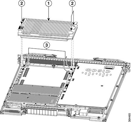
|
||||||||||
| Step 4 |
Place the removed Downstream PHY module in an antistatic bag. |
What to do next
Installing the Downstream PHY Module in the Interface Line Card
The Downstream PHY module is installed as a replacement or an upgrade from downstream D3.0 module to a downstream D3.1 module.
Caution |
Do not touch the cLGA connector. |
Before you begin
Prerequisites
-
Attach an ESD-preventive wrist strap to your wrist and connect the other end to the grounding lug connected to the chassis.
-
Be aware of the weight and size of the equipment. Handle it with care.
Restrictions
-
Ensure that the guide holes at the rear of the Downstream PHY module are aligned properly. If the Downstream PHY module alignment is reversed, the cLGA connector guide pins will damage the connecting surface of the Downstream PHY module.
Required Tools and Equipment
-
ESD-preventive wrist strap
-
T10 Torx-blade torque driver
-
Downstream PHY module (Refer to the FRU list and the ordering information for the correct module.)
Procedure
| Step 1 |
Grasp the Downstream PHY module by its sides. 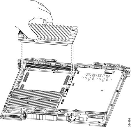 |
||
| Step 2 |
Align the front and rear guide holes of Downstream PHY module with the front and rear guide pins on the line card. |
||
| Step 3 |
Gently lower the Downstream PHY module on to the guide pins of the line card. |
||
| Step 4 |
Tighten the three retaining screws using a T10 Torx-blade torque screwdriver.
|
What to do next
-
After the Interface line card is installed and reloading it, verify that the downstream PHY module is upgraded from downstream D3.0 to downstream D3.1 module using the show inventory command. For more details on the verification, refer to Verifying the Downstream PHY Module Upgrade.
Removing the Upstream PHY Module in the Interface Line Card
The Upstream PHY module is removed for replacement or upgrade.
Before you begin
Prerequisites
-
Attach an ESD-preventive wrist strap to your wrist and connect its end to the grounding lug that is connected to the chassis.
-
Be aware if the weight and size of the equipment. Handle the equipment with care.
-
Remove the interface line card.
Restrictions
-
Ensure that a working Upstream PHY module is available for replacement.
-
Ensure that the interface line card removed for the Upstream PHY module replacement, is re-installed or replaced by another interface line card or a line card blank, within three minutes of removal.
Caution
The line card slot must not remain empty for more than three minutes, to avoid critical thermal alarms relating to overheating of individual components.
Required Tools and Equipment
- Upstream module extractor
tools:
- Extractor plunger assembly
- Extractor pull assembly
- ESD-preventive wrist strap
- T10 Torx-blade torque screwdriver
- 3/16" flat-blade torque screwdriver
- Configured replacement RF line card or line card blank
- Upstream D3.1 modules for upgrade
- Antistatic mat or bag
Procedure
| Step 1 |
Loosen all four T10 screws on the upstream module by turning the screws in counter clockwise direction using a T10 Torx screwdriver. Make sure that all four screws are disengaged properly. |
| Step 2 |
To attach the upstream module extractor plunger assembly, align the plunger assembly between the center heatsink fin separation and the last row of heatsink fins. |
| Step 3 |
Firmly press down the thumb rest on the flange of the plunger assembly and snap onto the heatsink. Do not press the plunger. |
| Step 4 |
To engage the extractor catch with the heatsink, press the extractor catch release button. |
| Step 5 |
To attach the extractor pull assembly, align the pull assembly between the center heatsink fin separation and the last row of heatsink fins. |
| Step 6 |
Firmly press down the thumb rest on the flange of the plunger assembly and snap onto the heatsink. |
| Step 7 |
Press the extractor catch release button to engage the extractor catch with the heatsink. |
| Step 8 |
Check whether all four T10 screws on the upstream module are completely loose. |
| Step 9 |
To disengage the connectors and release the upstream module, hold the two assemblies using the flange and then using your thumb firmly press down the plunger on the extractor plunger assembly and pull the upstream module up keeping the level straight. Place the upstream module on an antistatic mat. |
| Step 10 |
To remove the extractor assemblies from the upstream module, press the extractor catch release button on both the extractor assemblies and pull them up. |
What to do next
Installing the Upstream PHY Module in the Interface Line Card
The Upstream PHY module is installed as a replacement or an upgrade from downstream D3.0 module to a downstream D3.1 module.
Before you begin
Prerequisites
-
Attach an ESD-preventive wrist strap to your wrist and connect its end to the grounding lug that is connected to the chassis.
-
Be aware if the weight and size of the equipment. Handle the equipment with care.
Required Tools and Equipment
- ESD-preventive wrist strap
- T10 Torx-blade torque screwdriver
- 3/16" flat-blade torque screwdriver
- Configured replacement RF line card or line card blank
- Upstream D3.1 modules for upgrade
- Antistatic mat or bag
Procedure
| Step 1 |
Align the guide holes on the module with the alignment posts on the RF line card. |
| Step 2 |
Firmly press the module down to seat the connectors. Do not use excessive force. |
| Step 3 |
Tighten all the four T10 securing screws in clockwise direction to a torque of 8 pound inch. |
| Step 4 |
Snug-tighten all the screws in the clockwise direction in the same order as done in the previous step. |
What to do next
-
Remove the replacement RF line card or the line card blank from the chassis.
-
And then install the upgraded RF line card in the chassis.
-
Verify whether the version of the control FPGA is displayed as 00020009 using the show platform diag command.
-
Verify whether the PID of the upstream PHY module on the upgraded RF line card is displayed as CBR-D31-US-MOD using the show diag slot slot_number eeprom details command on the Supervisor.
 Feedback