Maintaining the Interface and PIC Cards in the Cisco cBR Chassis
 Note |
Any time a physical Online Insertion/Removal (OIR) is performed, the removed module must be left out 30-60 seconds before re-inserting it in the cBR-8 chassis. |
Maintaining the DOCSIS MAC/PHY Interface and PIC Card
Removing the DOCSIS MAC/PHY Interface Line Card from the Cisco cBR Chassis
It is not necessary to power down the chassis to remove an DOCSIS MAC/PHY interface line card.
Before you begin
-
Attach an ESD-preventive wrist strap to your wrist and connect the other end to the grounding lug connected to the chassis.
-
Be aware of the weight and size of the equipment. Handle it with care.
-
Before removing an interface line card, ensure that one of the following cards is available for immediate replacement in the chassis:
-
replacement DOCSIS MAC/PHY interface line card
-
line card blank

Caution
After removing a line card or a line card blank from an operational chassis, install the replacement line card or line card blank in the chassis within three minutes to avoid critical thermal alarms relating to overheating of individual components.
-
Required Tools and Equipments
- ESD-preventive wrist strap
- 3/16" flat-blade torque screwdriver
- Antistatic bag
Procedure
| Step 1 |
Loosen the captive screws on the appropriate slot using a 3/16" flat-blade torque screwdriver until the red bands are visible on the captive screws. |
||||
| Step 2 |
Pull the spring-loaded ejectors on the card until they release and are perpendicular to the faceplate. This disengages the card from the chassis. |
||||
| Step 3 |
Carefully slide the card out of its slot applying even pressure using both your hands. |
||||
| Step 4 |
Grasp the faceplate of the card with one hand and place your other hand under the card to support its weight, and remove the card from its slot. |
||||
| Step 5 |
Place the removed card in an antistatic bag.
|
What to do next
-
Replace the Interface Line Card or install a line card blank (as required).
Removing the UCH.8 Connectors from the RF PIC
Three UCH.8 connectors are connected to the RF Through PIC. To remove a PIC, the UCH.8 connectors connected to the PIC must be removed first. This procedure is used only for RF Through PICs. The following steps describe how to remove one UCH.8 connector. Repeat the procedure to remove all the three UCH.8 connectors.
Before you begin
-
Attach an ESD-preventive wrist strap to your wrist and connect the other end to the grounding lug connected to the chassis.
Required Tools and Equipment
- ESD-preventive wrist strap
- 3/16" flat-blade screwdriver
Procedure
| Step 1 |
Loosen the lead screw on the UCH.8 connector using a 3/16" flat-blade screwdriver. |
| Step 2 |
Loosen and pull the UCH.8 connector until it is disconnected from the port. |
What to do next
Remove the RF Through PIC (if required).
Removing the RF PIC from the Cisco cBR Chassis
Before you begin
-
Before removing an RF PIC, ensure that one of the following cards is available for immediate replacement in the chassis:
-
replacement RF Through PIC or RF Protect PIC
-
PIC Blank
Caution
After removing the PIC or a PIC Blank from an operational chassis, install the replacement PIC or blank PIC in the chassis within three minutes to avoid critical thermal alarms relating to overheating of individual components.
-
-
Attach an ESD-preventive wrist strap to your wrist and connect the other end to the grounding lug connected to the chassis.
-
Be aware of the weight and size of the equipment. Handle it with care.
- To remove an RF PIC, first remove the UCH.8 connectors.
Required Tools and Equipments
-
ESD-preventive wrist strap
-
3/16" flat-blade screwdriver
-
Antistatic bag
Procedure
| Step 1 |
Loosen the captive screws on the appropriate slot using a 3/16" flat-blade torque screwdriver until the red bands are visible on the captive screws. |
| Step 2 |
Pull the ejectors levers until the PIC is disengaged from the connectors on the midplane. Carefully slide the PIC out of the slot applying even pressure using both your hands. 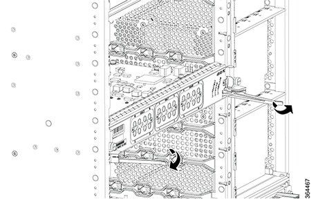  |
| Step 3 |
Place the removed card in an antistatic bag. |
What to do next
Removing the cLGA Connector from an Interface Line Card
The cLGA 10 X 22 Position .050 C/L Connector (cLGA connector) must be removed only in case of a failure or fault.
Before you begin
-
Attach an ESD-preventive wrist strap to your wrist and connect the other end to the grounding lug connected to the chassis.
-
Be aware of the weight and size of the equipment. Handle it with care.
-
Wear latex gloves while handling the cLGA connector, to prevent contamination of the connector surface.
Restrictions
-
Ensure that a replacement line card or line card blank is available for installation into the vacated line card slot.
-
Ensure that the replacement interface line card or line card blank is installed within three minutes of removal.
Caution
The line card slot must not remain empty for more than three minutes, to avoid shutdown of chassis due to overheating of the components.
Required Tools and Equipment
-
ESD-preventive wrist strap
-
Hex socket bit for 10830 cap-screw (used with a screwdriver with detachable bits)
Figure 5. Hex Socket Bit for 10830 Cap-Screw -
Replacement line card or line card blank (in case it is not possible to re-install the removed line card within three minutes)
-
Antistatic Bag
Procedure
| Step 1 |
Replace the protective cover on the cLGA connector by pinching the side clamps on the cover with your thumb and index finger and placing the cover in the cLGA connector and releasing the clamps. Ensure the clamp locks on the cLGA connector. |
| Step 2 |
Loosen and remove the two 10830 cap-screws that fasten the cLGA connector to the PCB. |
| Step 3 |
Hold the cLGA connector with protective cover using your thumb and index finger. Lift the cLGA connector up until the guide pins at the bottom of the cLGA connector are removed from the guide holes in the PCB. |
| Step 4 |
Place the cLGA connector in an antistatic bag. |
What to do next
Installing the cLGA Connector on the Line Card PCB
Note |
Do not remove the cap of the cLGA connector until the Downstream D3.0 Module is ready to be installed. |
The cLGA connector must be installed before installing the Downstream D3.0 Module, during replacement of the Downstream D3.0 Module, on the interface line card.
Before you begin
-
Attach an ESD-preventive wrist strap to your wrist and connect the other end to the grounding lug connected to the chassis.
-
Be aware of the weight and size of the equipment. Handle it with care.
-
Wear latex gloves while handling the cLGA connector, to prevent contamination of the connector surface.
Restrictions
- Install the interface line card in the slot corresponding to the RF Protect or RF Through PIC installed.
Required Tools and Equipment
- ESD-preventive wrist strap
-
cLGA Connector Installation kit consisting of the following:
- Hex socket bit for 10830 cap-screw (use with a screwdriver with detachable bits)
-
10830 cap-screws
Figure 7. 10830 Cap-screws - cLGA 10 X 22 Position .050 C/L Connector (cLGA connector)
Note
After installation, save the hex socket bit for future use. These will be required while removing the cLGA connector.
Procedure
| Step 1 |
Hold the cLGA connector by the sides of its protective cap, using your thumb and index finger.
|
||
| Step 2 |
Align the guide pins below the cLGA connector with the guide holes in the PCB and set the cLGA connector on the PCB. |
||
| Step 3 |
Insert the 10830 cap-screws into the and tighten using the hex socket driver with a torque of 4.4 lb-inch (0.5 Nm). |
What to do next
-
Remove the protective cover from the cLGA connector before the Downstream D3.0 Module is installed.
Figure 8. Removing the Protective Cover from the cLGA Connector
Maintaining the DOCSIS MAC Interface and PIC Card
Removing the DOCSIS MAC Interface Line Card from the Cisco cBR Chassis
It is not necessary to power down the chassis to remove an DOCSIS MAC interface line card.
Before you begin
-
Attach an ESD-preventive wrist strap to your wrist and connect the other end to the grounding lug connected to the chassis.
-
Be aware of the weight and size of the equipment. Handle it with care.
-
Before removing an interface line card, ensure that one of the following cards is available for immediate replacement in the chassis:
-
replacement DOCSIS MAC interface line card
-
line card blank
Caution
After removing a line card or a line card blank from an operational chassis, install the replacement line card or line card blank in the chassis within three minutes to avoid critical thermal alarms relating to overheating of individual components.
-
Required Tools and Equipments
-
ESD-preventive wrist strap
-
3/16" flat-blade torque screwdriver
-
Antistatic bag
Procedure
| Step 1 |
Loosen the captive screws on the appropriate slot using a 3/16" flat-blade torque screwdriver until the red bands are visible on the captive screws. |
||||
| Step 2 |
Pull the spring-loaded ejectors on the card until they release and are perpendicular to the faceplate. This disengages the card from the chassis. 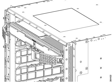 |
||||
| Step 3 |
Carefully slide the card out of its slot applying even pressure using both your hands. 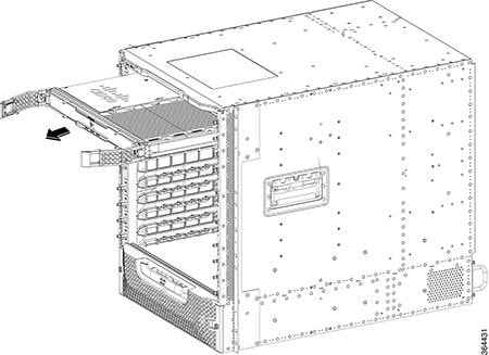 |
||||
| Step 4 |
Grasp the faceplate of the card with one hand and place your other hand under the card to support its weight, and remove the card from its slot. |
||||
| Step 5 |
Place the removed card in an antistatic bag.
|
What to do next
-
Replace the Interface Line Card or install a line card blank (as required).
Removing the Digital PIC from the Cisco cBR Chassis
Before you begin
-
Before removing an Digital PIC, ensure that one of the following cards is available for immediate replacement in the chassis:
-
replacement Digital Through PIC or Digital Protect PIC
-
PIC Blank
Caution
After removing the PIC or a PIC Blank from an operational chassis, install the replacement PIC or blank PIC in the chassis within three minutes to avoid critical thermal alarms relating to overheating of individual components.
-
-
Attach an ESD-preventive wrist strap to your wrist and connect the other end to the grounding lug connected to the chassis.
-
Be aware of the weight and size of the equipment. Handle it with care.
Required Tools and Equipments
-
ESD-preventive wrist strap
-
3/16" flat-blade screwdriver
-
Antistatic bag
Procedure
| Step 1 |
Loosen the captive screws on the appropriate slot using a 3/16" flat-blade torque screwdriver until the red bands are visible on the captive screws. |
| Step 2 |
Pull the ejectors levers until the PIC is disengaged from the connectors on the midplane. Carefully slide the PIC out of the slot applying even pressure using both your hands. |
| Step 3 |
Place the removed card in an antistatic bag. |
 Feedback