Loopback Tests for T1/56K Lines
Available Languages
Contents
Introduction
When a serial line does not come up as it must, the best way to troubleshoot the circuit is to perform loopback tests. Loopback tests allow you to isolate pieces of the circuit, and test them separately. Begin loopback tests on the customer premises with channel service unit/data service unit (CSU/DSU) loopback tests. Then proceed on to loopback tests that involve the telco or provider.
Prerequisites
Requirements
There are no specific requirements for this document.
Components Used
The information in this document is based on Cisco IOS® Software Release 12.0.
Conventions
Refer to Cisco Technical Tips Conventions for more information on document conventions.
Background Information
Two kinds of loopback tests can be used to isolate problems on the serial link: software loopbacks and hardware plug loopbacks. Whether it is an internal or external CSU/DSU, you can do both software and hardware loopbacks back towards the router.
-
Software local loopbacks are usually implemented with a Cisco IOS configuration command, or with a loopback button for some CSU/DSUs.
-
A loopback plug or cable inserted into the CSU/DSU can be used for hardware loopbacks.
If CSU/DSU loopback tests prove that the router equipment, CSU/DSU, and connecting cables are not faulty, conduct further tests with the telco or provider of the circuit.
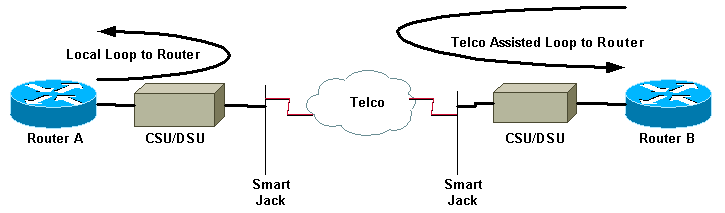
This diagram describes the various loopback tests you can do to isolate your serial line issue accurately.
 Warning: All loopback testing is intrusive to the circuit. Therefore, while you troubleshoot your circuit, you will be unable to pass traffic across that link.
Note: All loopback testing is done with High-Level Data Link Control (HDLC) encapsulation.
Perform Loopback Tests at the CSU/DSU
Note: Refer to the Local Loop to Router in the diagram above.
Although you can do both software and hardware loopback tests on a CSU/DSU, a loopback plug is more effective to isolate problems. A software loopback towards the router usually only loops the DSU functionality of a CSU/DSU. A hardware loopback is able to prove that the entire CSU/DSU is not at fault.
CSU/DSU Software Loopback
For an internal CSU/DSU, the software loopback is implemented with a Cisco IOS configuration command. For most platforms, the command takes the form loopback, loopback dte or loopback local. This loops the circuit from inside the CSU/DSU back towards the router, and therefore isolates that section of the circuit.
In order to run the loopback test on channelized T1s using Primary Rate Interface (PRI) or channel associated signaling (CAS), you need to use the channel-group T1 controller command. Use this command to create one or more serial interfaces mapped to a set of timeslots in the channelized T1.
Note: If the T1 is configured as a PRI, you need to remove the pri-group before you use the channel-group command.
If you wish to run a software loopback at the local CSU, configure loopback local in the controller. Here is an example that uses these commands:
Router#configure terminal

Enter configuration commands, one per line.  End with CNTL/Z.
Router(config)#controller t1 0
Router(config-controller)#no pri-group timeslots 1-24
Router(config-controller)#channel-group 0 timeslots 1-24 speed 64

!--- This automatically creates a single Serial0:0 interface.

Router(config-controller)#loopback local

!--- The loopback local command above is only necessary for software loopbacks.

Router(config-controller)#exit
Router(config)#interface serial 0:0
Router(config-if)#encapsulation hdlc

!--- Note: All loopback testing is done with hdlc encapsulation.
Note: This example creates a single Serial0:0 interface (where the first 0 stands for the controller and the second 0 represents the channel-group number), and uses all 24 timeslots for a total of 1.536Mbps bandwidth. If you use Super Frame (SF) framing type and alternate mark inversion (AMI) linecoding, use "speed 56" in the channel-group command. SF/AMI does not support clear-channel DS0s.
Please refer to the Diagnostic Tests while in Loopback section for information on what should be verified while in loopback.
CSU/DSU Hardware Loopback
The hardware loopback plug test is used to see if the router and the entire CSU/DSU has any faults. If a router passes a hardware loopback plug test, then the problem exists elsewhere on the line. Refer to the directions below for creating a loopback plug, and then insert the plug into the network (telco) side of the CSU/DSU.
For the hardware loopback test, first perform the steps described in the software loopback section, except for configuring loopback local on the controller. If you have configured loopback local on the controller, undo it through the no loopback local command before you proceed.
Please refer to the Diagnostic Tests while in Loopback section for information on what you must verify while in loopback.
Loopback Plugs
Note: The pins on an RJ-45 cable plug are numbered from 1 through 8. With the metal pins of the plug facing toward you, pin 1 is the leftmost pin.
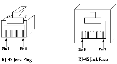
The T1 CSU/DSU has a pinout different from the four-wire 56K CSU/DSU. The connector for the T1 CSU/DSU is an RJ-48C. The connector for the four-wire 56k CSU/DSU is an RJ-48S. Both connectors are compatible with RJ-45 plugs.
-
Complete these steps to create a loopback plug for a T1 CSU/DSU:
-
Use wire cutters to create a working RJ-45 cable that is 5 inches long with an attached connector.
-
Strip the wires.
-
Twist the wires from pins 1 and 4 together.
-
Twist the wires from pins 2 and 5 together.
-
Leave the rest of the wires alone.
-
-
Complete these steps to create a loopback plug for a 56K CSU/DSU:
-
Use wire cutters to create a working RJ-45 cable that is 5 inches long with an attached connector.
-
Strip the wires.
-
Twist the wires from pins 1 and 7 together.
-
Twist the wires from pins 2 and 8 together.
-
Leave the rest of the wires alone.
-
Telco-Assisted Loopback Tests
Note: Refer to the Telco Assisted Loop to Router in the diagram above.
Use CSU/DSU tests to test the CSU/DSU, router, and cable that connects them (for an external CSU/DSU) on both sides of the circuit. If you can rule out a problem with them, involve the telco or provider. These loopback tests are done with the assistance of the telco, but are not done independently by the telco.
Note: These tests are not the same as the diagnostic or Bit Error Rate Test (BERT) testing on the line that the telco performs.
For these loopback tests, you must involve the telco since you are ask them to provide loopbacks towards your premises from the telco switches. Monitor the looped circuit from the router. In order to do this, you need to have the telco "split the circuit" at the telco switch closest to your router. For example, the telco must supply a loopback at the first telco switch that your circuit passes through, and loop that circuit back towards your router. In this way you can isolate the telco cloud of switches. You can then test only the portion of the circuit between the first telco switch and your CSU/DSU, SmartJack, and router.
Please refer to the Diagnostic Tests While in Loopback section for information on what you must verify while in loopback.
If you complete this "First Switch" testing, and prove it to run free of errors, perform the same procedure on the remote end of the circuit. The remote end is the router on the other side of the provider cloud. If the remote end is your Internet service provider (ISP), you must involve the ISP to help test this portion of the circuit.
Test the "First Switch" on both sides. If it is clean, you can use this information to indicate that the problem is within the telco cloud. The telco can investigate with their own testing of the circuit at this point. Alternatively the telco can continue the loopback testing with you. The telco can do this by backing off one switch at a time further into the telco cloud. At each switch, they should do a loopback towards the local router.
If "First Switch" tests indicate a problem in the circuit between the first telco switch and your router, the telco can help test that circuit portion. The telco can loop various equipment for diagnostic tests between the SmartJack that you connect your CSU/DSU to and the first telco switch. Bear in mind that, if you have an extended demarc, you should investigate it as a potential problem area. Extended demarcs, when done incorrectly, can produce errors on the line. Extended demarcs occur when the provider extends the original demarc point to a location closer to the customer equipment.
Diagnostic Tests While in Loopback
The best test to run while in any of the loopbacks described above is an extended ping. You should run this test and monitor the show interface serial command for errors on the interface.
Prepare for the Extended Ping Test
Complete these steps to prepare for the extended ping test:
-
Use the show interface serial command to verify that the router has HDLC encapsulation on the interface, and that the interface sees the loopback.
Here is an example of the first few lines of the output:
Router#show interface serial 0
Serial0 is up, line protocol is up (looped)
Hardware is HD64570
Internet address is 10.1.1.1, subnet mask is 255.255.255.0
MTU 1500 bytes, BW 1544 Kbit, DLY 20000 usec, rely 255/255, load 1/255
Encapsulation HDLC, loopback set, keepalive set (10 sec)
...
-
Use the show running-config command to see if the interface has a unique IP address that is not shared with any other interface.
If the serial interface above does not have an IP address of its own, obtain a unique address and assign it to the interface.
Router(config-if)#ip address 172.22.53.1 255.255.255.0
-
Use the clear counters command to clear the interface counters.
For example:
 Router#clear counters
 Clear "show interface" counters on all interfaces [confirm]
 Router#
-
Perform the extended ping test as described in the Perform Extended Ping Tests section.
Perform Extended Ping Tests
The ping command is a useful test available on Cisco internetworking devices as well as on many host systems. In TCP/IP, this diagnostic tool is also called an Internet Control Message Protocol (ICMP) Echo Request.
Note: The ping command is particularly useful when the show interfaces serial output registers high levels of input errors.
Cisco internetworking devices provide a mechanism to send many ping packets in sequence automatically.
Complete these steps to perform serial line extended ping tests:
-
Perform the extended ping test. To do so, complete these steps:
-
Type: ping ip
-
Target address = enter the IP address of the local interface to which IP address was just assigned
-
Repeat count = 50
-
Datagram size = 1500
-
Timeout = press ENTER
-
Extended cmds = yes
-
Source Address = press ENTER
-
Type of service = press ENTER
-
Set Df bit in ip header = press ENTER
-
Validate reply data = press ENTER
-
Data pattern: 0x0000
-
Press ENTER three times.
Notice that the ping packet size is 1500 bytes, and that we perform an all zeros ping (0x0000). Also, the ping count specification is set to 50. Therefore, in this case, fifty 1500 byte ping packets are sent out.
Here is a sample output:
Router#ping ip
Target IP address: 172.22.53.1
Repeat count [5]: 50
Datagram size [100]: 1500
Timeout in seconds [2]:
Extended commands [n]: yes
Source address or interface:
Type of service [0]:
Set DF bit in IP header? [no]:
Validate reply data? [no]:
Data pattern [0xABCD]: 0x0000
Loose, Strict, Record, Timestamp, Verbose[none]:
Sweep range of sizes [n]:
Type escape sequence to abort.
Sending 50, 1500-byte ICMP Echos to 172.22.53.1, timeout is 2 seconds:
Packet has data pattern 0x0000
!!!!!!!!!!!!!!!!!!!!!!!!!!!!!!!!!!!!!!!!!!!!!!!!!!
Success rate is 100 percent (50/50), round-trip min/avg/max = 4/4/8 ms
Router#
-
-
Perform additional extended ping tests with different data patterns.
For example:
Repeat step 1, but use a Data Pattern of 0x1111
Repeat step 1, but use a Data Pattern of 0xffff
Repeat step 1, but use a Data Pattern of 0xaaaa
-
Verify that all the extended ping tests were 100 percent successful.
-
Examine the show interface serial command output to determine whether input errors have increased.
If input errors have not increased, the local hardware (DSU, cable, router interface card) is probably in good condition. Also look for cyclic redundancy check (CRC), frame, or other errors. Look at the fifth and sixth line from the bottom of the show interface serial command output to verify this.
If all pings are 100 percent successful and input errors have not increased, the equipment in this portion of the circuit is probably in good condition. Move on to the next loopback test to be performed.
-
Remove the loopback from the interface. To do so, remove the loopback plug, the software loopback commands, or request the telco to remove their loopback. Then restore your router to the original setting.
Related Information
 Feedback
Contact Cisco
- Open a Support Case

- (Requires a Cisco Service Contract)