Architecting the Telco Data Center with Cisco NX-OS and NDFC
Available Languages
Bias-Free Language
The documentation set for this product strives to use bias-free language. For the purposes of this documentation set, bias-free is defined as language that does not imply discrimination based on age, disability, gender, racial identity, ethnic identity, sexual orientation, socioeconomic status, and intersectionality. Exceptions may be present in the documentation due to language that is hardcoded in the user interfaces of the product software, language used based on RFP documentation, or language that is used by a referenced third-party product. Learn more about how Cisco is using Inclusive Language.
Telecom service provider Data Center (DC) networks are going through a massive transformation. Open RANs (Radio Access Networks), distributed edge applications, and 5G core deployments are the three main drivers of these transitions.
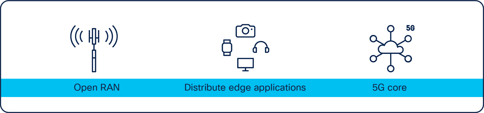
Key drivers for telco service provider data center network evolution
Open RAN (O-RAN) is on top of mind for most communication Service Providers (SPs). SPs are trying to move away from proprietary appliance-based systems to open multi-vendor RAN, where they can purchase components from different hardware and software vendors. SPs have traditionally been limited by vendor lock in which in turn has restricted their capability to negotiate cost and to innovate. With open RAN, they can buy servers from one vendor, virtualization or container platforms from a second vendor, and RAN software applications from a third. This opens a range of opportunities for communication service providers in terms of saving cost, better flexibility, openness, scale, and innovations they can use for both their own telco applications and enterprise applications in their data centers.
Service providers are increasingly positioning their own infrastructure like packet core (user plane function), caching, and service chaining at the Edge DC. By putting these data intensive applications at the edge, SPs save cost of transport network and provide better experience for their end customers. Additionally, they are also deploying latency sensitive enterprise applications from different industries such as health care, IoT, gaming, CDN etc in the Edge DC.
Edge data centers support low latency requirements for these applications by placing dense processing power at localized Points of Presence (PoPs) geographically close to end users and their devices, while also providing the necessary bandwidth to support rich, immersive experiences. All the above use cases are continually increasing the demand for edge DCs.
Telcos were previously deploying both physical and virtual packet core in central DCs. With 5G, there is a growing deployment of containerized packet core, which has impact on overall scale and convergence on the DC fabric. This document provides a lot of information about the specific features developed on Cisco Nexus® platform for 5G packet core deployment.
While there is tremendous opportunity in front of service providers with the O-RAN, distributed edge applications and 5G deployment, it brings a ton of challenges since applications are getting decomposed, virtualized, and deployed in a distributed fashion across multiple DCs. The following diagram shows the telco DC landscape with different applications deployed in different datacenters.
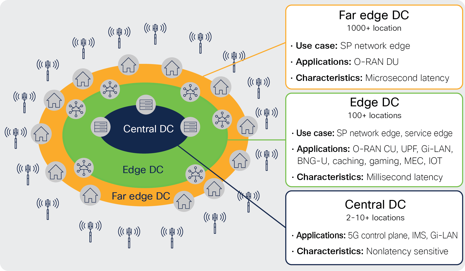
Telco DC landscape
In the Open-RAN deployment, there are three components. Open radio unit (O-RU), Open Distributed unit (O-DU), and Open Control unit (O-CU). Open Radio unit is typically a hardware appliance that is deployed on the cell site location. O-DU is deployed in a far edge location to meet strict latency requirements. For a typical Open-RAN deployment, customer would deploy thousands of far edge DCs to host O-DUs.
Latency-sensitive applications, such as O-CU, User Plane Function (UPF) of packet core, gaming, Mobile Edge Computing (MEC), and IoT, are deployed in edge DCs. These applications typically require millisecond latency and often require high bandwidth. Customers typically have hundreds of such edge DCs.
Typical non-latency sensitive applications, such as 5G control planes and voice applications such as IMS, are deployed in central DCs. In a typical deployment, customers would have 2 to 10+ such central DCs, depending on the operating country's geographical and population size.
From the telco DC landscape, it is clear that telecom operators need a solution to automate and operate distributed DCs at scale. This white paper explains how telco customers can deploy Cisco NX-OS and Nexus Dashboard Fabric Controller to deploy 5G, edge, and Open-RAN applications.
Telco data center architecture with Cisco NX-OS and NDFC
Cisco NX-OS, Cisco Nexus Dashboard Fabric Controller (NDFC), and Cisco Nexus Dashboard Orchestrator (NDO) provide a complete solution for telco providers to build high-performance, massive, scalable data centers distributed across geographical locations with centralized management and consistent policy. It powers use cases such as Open RAN, 5G packet core, IOT, CDN, and gaming, etc.
The Cisco NX-OS–based data-center design aligns with the distributed telco cloud model and 5G architecture to host a wide range of core and edge services in the telco data-center landscape. Figure 1 shows the Cisco NX-OS architecture for a distributed telco data-center fabric solution providing connectivity to various core services in the edge, regional, and central data centers.
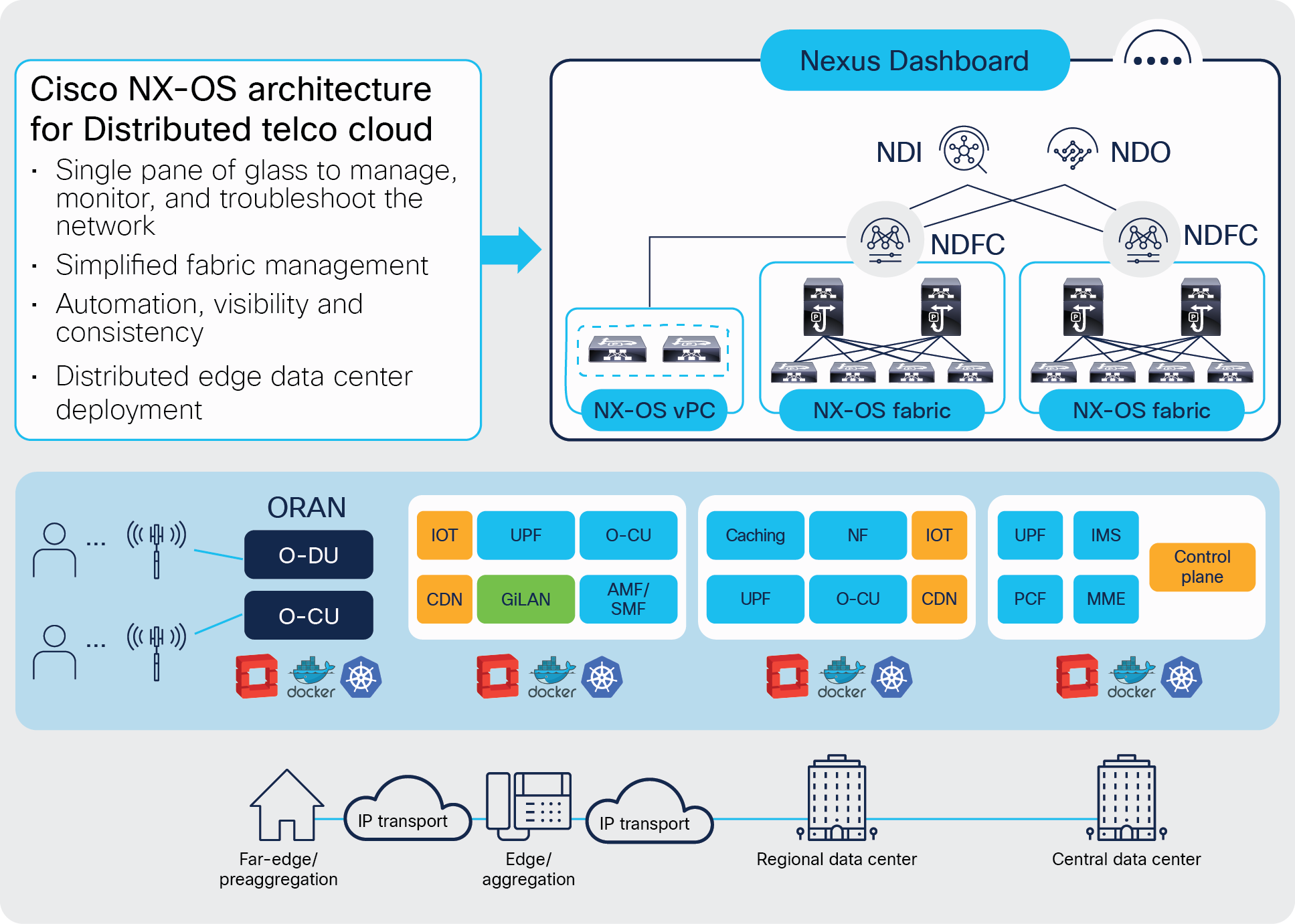
Cisco NX-OS architecture for distributed telco data centers
Building blocks of Cisco NX-OS telco data center
The next-generation Cisco NX-OS powered telco data center has the following key components:
● Fabric switches
● Cisco Nexus Dashboard
◦ Nexus Dashboard Fabric Controller
◦ Nexus Dashboard Orchestrator
◦ Nexus Dashboard Insights
The following section provides details on each of these components.
Fabric switches
The fabric is built with a rich portfolio of Cisco Nexus 9000 Series Switches in a spine-and-leaf CLOS architecture. It provides high-performance fabric switches with different port densities and speeds (from 100M to 400G) along with wire-rate security and telemetry.
With Cisco Nexus 9000 Series, the choices of switches for different layers include the following (please note that the choices are not limited to the examples given below):
● Leaf switches: Cisco Nexus 9300-GX2, Cisco Nexus 9300-GX, Cisco Nexus 9300-FX3, Cisco Nexus 9300-FX2, Cisco Nexus 9300-FX Series switches, etc.
● Spine switches: Cisco Nexus 9332C and 9364C fixed spine switches, Cisco Nexus 9500 Series modular switches with different line-card options, etc.
For O-RAN deployments, the recommended switch model is Cisco Nexus 9300-FX3. This switch supports standard PTP telecom profiles (PTP 8275.1 and PTP 8275.2) with SyncE and PTP boundary clock functionality for enabling telco data center edge environments.
For more information, please refer to the data sheets on Cisco Nexus 9000 Series Switches.
Cisco Nexus Dashboard
Cisco Nexus Dashboard (ND) is a powerful application-hosting platform that transforms data center operations by providing a single launchpad to help operate and manage the telco infrastructure. Based on a horizontal scale-out architecture, Cisco Nexus Dashboard can unify operations across the edge, regional, and central data centers built with Cisco NX-OS. The intuitive Cisco Nexus dashboard platform brings together services, namely Cisco Nexus Dashboard Fabric Controller (NDFC) and Cisco Nexus Dashboard Orchestrator (NDO), which enable automation and orchestration of the data center fabric. It additionally supports integration of services, namely Cisco Nexus Dashboard Insights and Cisco Nexus Dashboard Data Broker, that help with day-2 operations.
All these services run exclusively as applications on top of the Cisco Nexus Dashboard cluster. The Nexus Dashboard cluster uses Kubernetes at its core, with customized extensions, thereby realizing a secure and scaled-out platform for deployment of microservices-based applications. Nexus Dashboard Cluster (provisioned as active/active high availability) provides High Availability (HA) for all applications running on that cluster.
Nexus Dashboard framework and components provide a seamless and symmetric look and feel across all its hosted services.
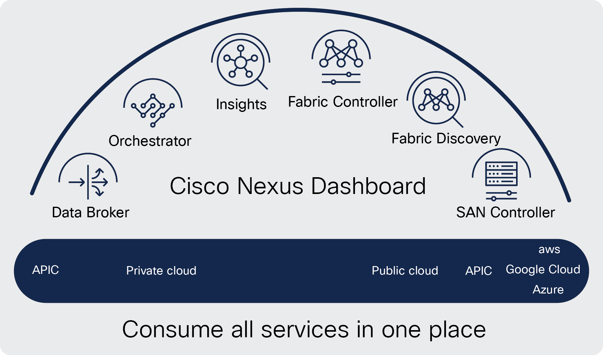
Cisco Nexus Dashboard
Cisco Nexus Dashboard Fabric Controller (NDFC)
Cisco Nexus Dashboard Fabric Controller (NDFC) (formerly Cisco Data Center Network Manager [DCNM]) is a comprehensive management and automation solution for Cisco NX-OS. NDFC can automate the configuration of the underlay network as well as automate the creation and extension of overlay networks and VRFs. Cisco NDFC also provides fabric inventory management, status of the fabric links, networks, and basic operations for the fabric.
Cisco Nexus Dashboard Orchestrator (NDO)
Because telco data centers are geographically distributed across sites, there is a need to simplify the creation of networks and VRFs and to ensure consistency across these sites. While NDFC manages multiple fabrics within a site, Nexus Dashboard Orchestrator (NDO) provides the operator a single point of access to define networks and VRFs that can then be extended within a site as well as across sites. NDO does this by communicating with all instances of NDFCs that are managing individual sites. To summarize, NDO for NDFC managed sites can be used to extend connectivity between sites, enable DCI automation, and act as a single point of management and consistent policy application across geographically dispersed sites for 5G distributed architecture.
Cisco Nexus Dashboard Insights
Cisco Nexus Dashboard Insights (NDI) is a microservices based modern application for network operations. It is hosted on Cisco Nexus Dashboard where Cisco NDFC sites are onboarded, and respective data from these sites is ingested and correlated by Nexus Dashboard Insights. Nexus Dashboard Insights helps with day-2 operations to provide visibility, proactively detecting anomalies with correlated network and application views. This in turn helps to proactively prevent outages as well as accelerate troubleshooting, thereafter remediating issues in these fabrics.
Benefits of using Cisco NX-OS for Telco data center deployments
Advanced technology features offered by the Cisco NX-OS based solution addresses the distinct and dynamic requirements for telco data centers. This section explores some of the key benefits of architecting a telco data center with Cisco NX-OS.
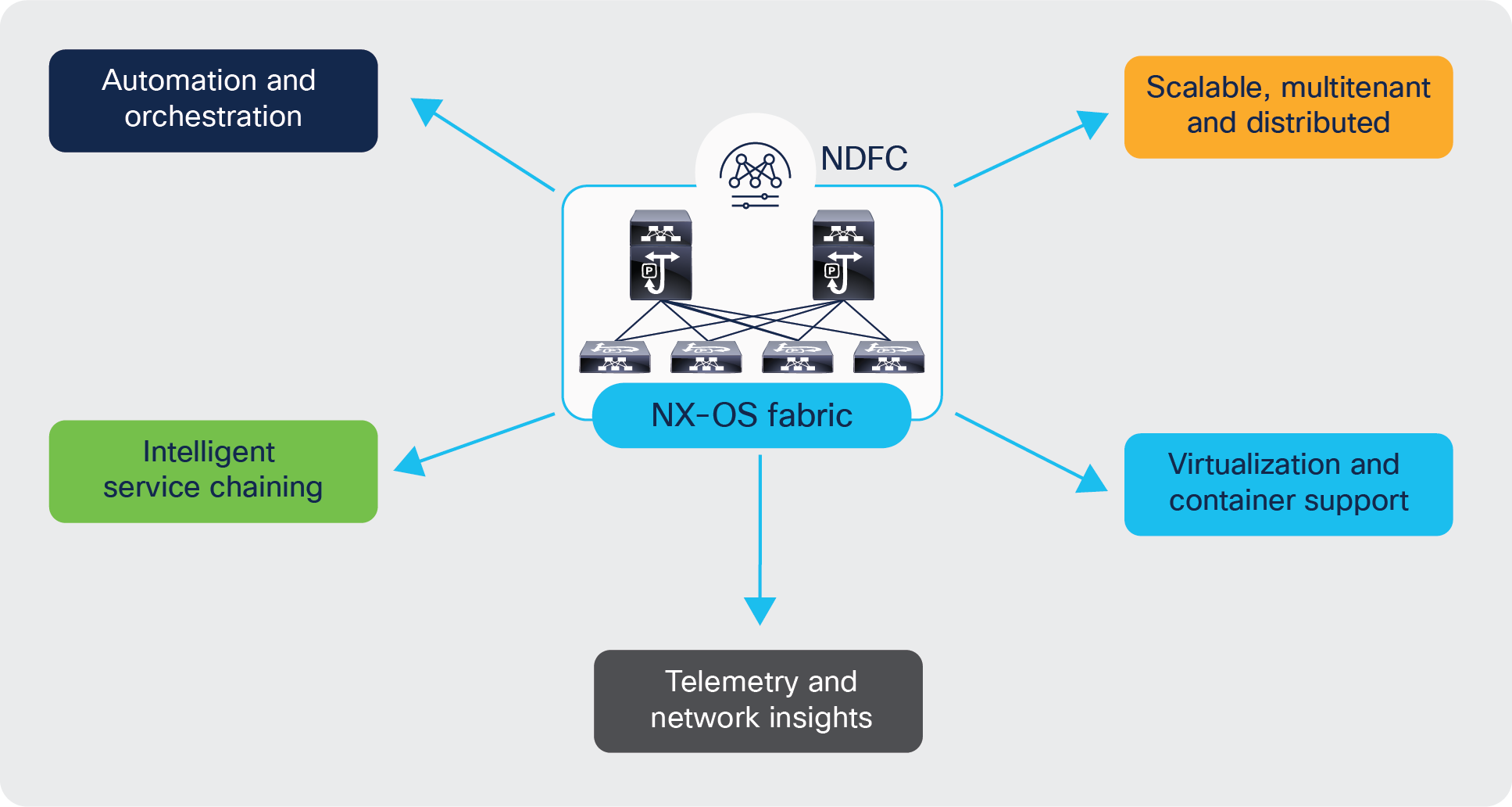
Cisco NX-OS fabric: Key benefits for telco data centers
Scalable, Multitenant, Distributed Telco data center fabrics
Any data center deployments must cater to high availability and high reliability with the capability to scale out. Cisco NX-OS fabrics built using VXLAN EVPN architecture, embodies all the above. VXLAN with BGP EVPN control-plane is a proven overlay for any data center deployment. VXLAN provides network slicing with VRFs, secure multitenancy with BGP EVPN control plane, and mobility with a distributed anycast gateway.
VXLAN with BGP EVPN also is an effective DCI solution to interconnect multiple fabrics within a site as well as across sites. This is enabled using the Cisco® VXLAN EVPN Multi-site solution. VXLAN Multi-site brings hierarchy to network deployment. It provides the ability to extend services across sites yet contains the fault domain within each site.
IPv4/IPv6/dual-stack support
The decision to go with an IPv4, IPv6, or dual-stack deployment in an NX-OS fabric is dependent on the packet core solution requirements. In order to make a network dual-stack, mobile subscribers need to get both IPv4 and IPv6 addresses. In addition, a mobile client source (IPv4/IPv6) needs to be able to reach both IPv4 and IPv6 internet address destinations, because there are websites on the internet that do not yet support IPv6.
The Cisco NX-OS fabric supports IPv4, IPv6, or dual-stack deployments. VXLAN BGP EVPN fabrics can be deployed with either IPv4 underlay or IPV6 underlay, and hosts in the overlay can be either IPv4 or IPv6.
NDFC:
Cisco Nexus Dashboard Fabric Controller (NDFC), our comprehensive data center automation tool, offers complete automation, extensive visibility, and consistent operations for your telco data center. NDFC accelerates fabric provisioning and bring-up from days to minutes and simplifies deployments from day zero through day N.
NDFC uses its enhanced “easy” fabric workflow for unified underlay and overlay provisioning of VXLAN BGP EVPN configurations on Cisco Nexus 9000 and 3000 series switches. The configuration of the fabric is achieved through a powerful, flexible, and customizable template-based framework.
NDFC powers day-0 operations by enabling device and configuration bootstrap based on switch roles in each fabric. Using minimal user inputs, and in a very short period of time, an entire fabric can be brought up with Cisco recommended best-practice configurations. NDFC also provides regular configuration compliance and remediation to keep the network state in sync.
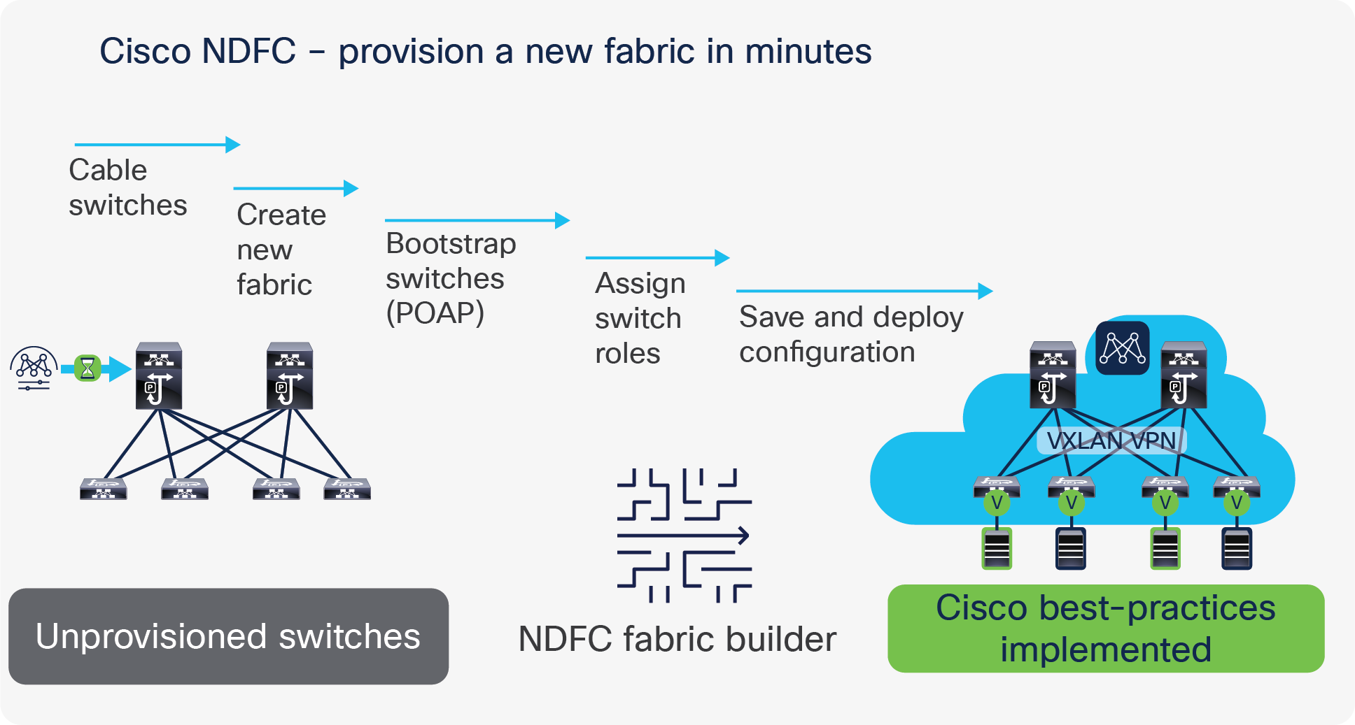
Provision a new fabric in minutes, with NDFC
Extensive Programmability
NDFC provides representational state transfer (RESTful) APIs that offer a simple approach to automate the network or application provisioning by integrating with existing automation tools in the telco data center. In addition to the NDFC GUI, the fabric can be fully manageable through the NDFC RESTful APIs using your preferred API management tools. The REST API documentation is packaged with the product and can be accessed through any browser.
Additionally, Ansible collections and HashiCorp Terraform providers published for NDFC enable infrastructure automation, help maintain network configuration as code, and embed the infrastructure configurations as part of the CI/CD pipeline for operational agility.
Cisco NDFC, with its rich set of open APIs, can easily fit into a service provider’s existing management and orchestration framework for end-to-end service-oriented automation.
For telco customers, network monitoring, auditing, capacity planning, and troubleshooting are particularly important aspects of day-to-day operations. Cisco Nexus 9000 Series Switches are equipped with rich software and hardware telemetry capabilities to fulfill these requirements.
Cisco NX-OS supports gRPC-based dial-out and gNMI-based dial-in streaming telemetry features to continuously stream data out of the network, providing near-real-time network monitoring. Both options support different encoding, transport, and data sources, including sources specific to Cisco such as DME (system model object), CLI/NX-API, and open standard sources, such as native YANG and OpenConfig.
Telco customers can additionally leverage Cisco’s turnkey application “Nexus Dashboard Insights (NDI)” to gain visibility into the network, to enable Proactive troubleshooting, and increase network availability / performance. NDI collects Telemetry data from various sources, ingests and processes the same to derive meaningful insights and recommended actions. Data center visibility use cases such as event analytics, resource utilization, flow analytics, Network health, Path and Latency measurement, Network performance etc., are provided thru the NDI dashboard. NDI also monitors all the devices in a network and provides complete network lifecycle management for datacenter operations.
One of the most important use cases in telco data centers is service chaining. Mobile traffic in a data center needs to go through a chain of service devices (such as Carrier-Grade Network Address Translation [CGNAT], Deep Packet Inspection [DPI], TCP optimizers, etc.) before it can be forwarded to the internet. The Cisco NX-OS feature Enhanced Policy-Based Redirect (ePBR) completely automates the service chaining capability by creating multiple policies and by enabling hop-by-hop traffic steering using policy-based routing/redirection policies. These policies enforce traffic redirection by monitoring service-element health and reachability.
Virtualization and container support
Telco data centers demand support for all types of workloads, including bare-metal, virtualized workloads and containers. This brings in an additional layer of virtual networking, offered by virtualized or cloud-native platforms, that introduces a siloed approach to manage networking in distinct environments.
Cisco NDFC provides a single pane of management and visibility into the virtual networking of these mixed environments. Through Virtual Machine Manager (VMM) integration, NDFC automates virtual network configurations and provides visibility of the endpoints deployed on multiple hypervisors and containers in a single view.
Mobile carriers are increasingly virtualizing packet-core functionality to reduce the dependency on specialized hardware and to meet the demands of network traffic driven by 5G. Virtualizing packet core also increases the speed of service delivery, on-demand scalability, and the ability to respond to real-time network conditions and user needs. The various packet-core functions, such as Mobility Management Entity (MME), Serving Gateway (SGW), and Packet data network Gateway (PGW), etc., are deployed as Networking Functions (NFs). These NFs participate in traffic-forwarding functions and peer with Cisco NX-OS fabrics over different interfaces.
This section focuses on some key requirements and network design considerations when connecting packet-core services to a Cisco NX-OS fabric and how they can be addressed and simplified using Cisco NX-OS for telco data center environments. It explains how we can go about interconnecting the NFs to the fabric along with traffic flow requirements and peering considerations for optimized flow of traffic.
Typically, packet core services deployments can include multiple virtualized or containerized instances and can spread across multiple racks, depending on capacity and throughput requirements.
Service loopback addresses and subscriber pool addresses configured on elements of packet core services are some of the key address types that require reachability from different places in a telco data center landscape.
In Packet Core, loopback interfaces are defined on elements of the Packet Core Services for each type of service interface (S1-MME, S1U, etc.) that it hosts. These loopback addresses are also called service loopback addresses. These interfaces are used for carrying various control and data plane traffic; therefore, the underlying network infrastructure must ensure reachability to these addresses or prefixes. Routing protocols employed in this solution need to ensure reachability of the service loopback addresses, especially between the eNodeBs/gNodeBs in radio access networks and packet core services in a telco data center.
Mobile subscribers attaching to an LTE network are assigned IPv4/IPv6/dual stack addresses from the subscriber pool range. The user-endpoint uses the IP address for accessing internet data; therefore, the underlying network infrastructure must ensure reachability to the address range from the perimeter internet layer for the return traffic along the path toward the user.
Packet core traffic forwarding requirements
● The following are some key requirements of NFs specific to telco workloads:
● Packet core NFs distributed across multiple racks and leaf nodes
● Flexibility to deploy NFs based on capacity in racks, servers, etc.
● ECMP support within the NX-OS fabric toward leaf switches connected to NFs
● ECMP from each leaf to all NFs hosted across multiple racks. ECMP must be supported, not just to directly connected NFs, but also to NFs that are reachable through the Layer- 3 fabric. If ECMP is only supported to directly connected NFs, then all leaf switches must have an equal number of NFs connected to it (ECMP); otherwise, NFs will receive unequal amounts of traffic, resulting in packet loss. Connecting equal amounts of NFs to all leaf switches may not be possible for many service providers; also, doing so is against the basic principle of allowing any NFs to be placed anywhere.
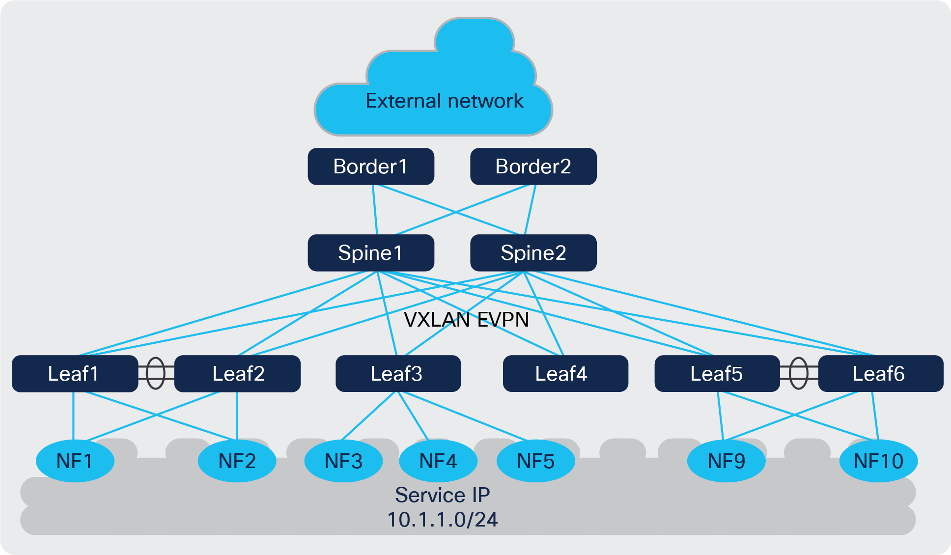
NFs deployed in a packet core with distributed service IP
● Load-balancing proportional to connected NFs: A widely distributed service IP or service subnet with a need for better per-NF load distribution. In Figure 8, Leaf1 and Leaf2 host one NF respectively, whereas Leaf3 hosts three NFs. There needs to be a way to indicate the presence of more NF instances attached to Leaf3, so that we can expect 1x the traffic load to go toward Leaf1 and Leaf2, and 3x the traffic load toward Leaf3.
● Routing and Bidirectional Forwarding Detection (BFD) over the NX-OS fabric, since each NF needs to do peering, not just with the leaf switches that are connected to it, but with other leaf switches as well. This peering across the fabric is required to support ECMP, faster convergence, and the capability to move NFs across the fabric.
NF deployment - Network design considerations
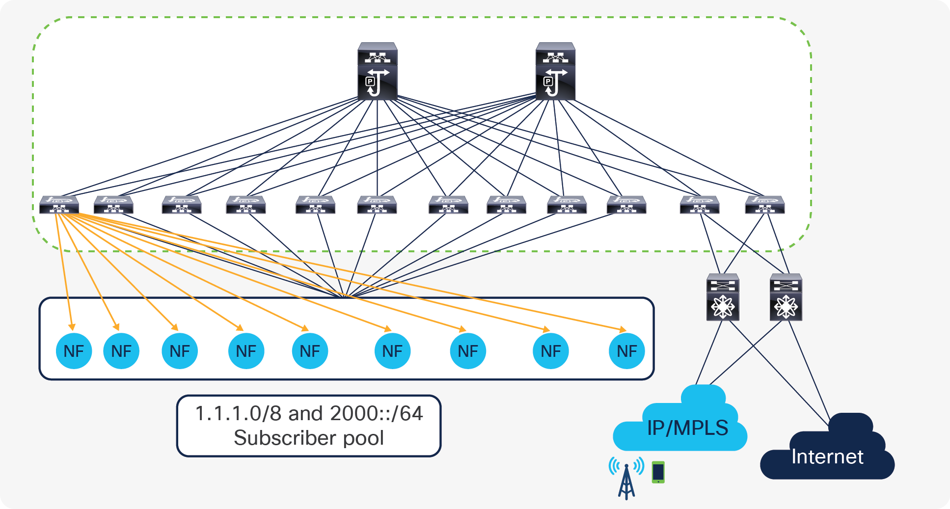
NFs that form the packet core can be peered with fabric switches using centralized route peering. As a best practice, it is always recommended to peer using vPC switches to provide better redundancy.
Centralized Routing Peering
With centralized route peering, all the NF nodes peer with one or a pair of switches (called anchor leaf switches). This simplifies the configuration of the physical network greatly because:
● BGP peering configuration is only needed on anchor nodes.
● The BGP peer configuration on all NF nodes is identical because they all peer with the same remote addresses.
Centralized route peering
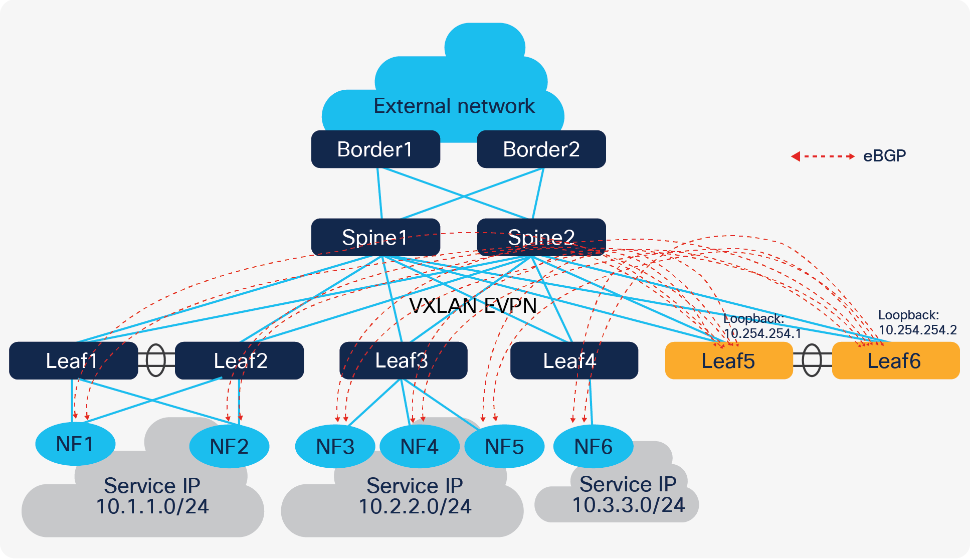
In Figure 9, Leaf5 and Leaf6 are the anchor nodes; all control plane connections are established between these two leaf switches and NF nodes. It is much easier to maintain this configuration; however, it does come with two challenges:
● Number of BGP neighbors supported by a single switch is limited.
● North-South (N-S) traffic is not optimized.
Most Cisco Nexus fixed switches support 1024 BGP neighbors, and modular switches support up to 2000 BGP neighbors. The number of nodes in most NF clusters is in this range, so in most cases, this first challenge is not really a problem. Also, distributing BGP peering between different anchor nodes is another option to help ease the situation.
Coming to the second challenge, since eBGP is used to form neighbors between NF and anchor nodes, the next hop address of routes learned on NF node is always the anycast gateway. The anycast gateway exists on all leaf switches that have an NF node connected to them. So, the N-S traffic from an NF is always routed by local switches. However, the traffic coming in from external sources will potentially “trombone” through the anchor nodes.
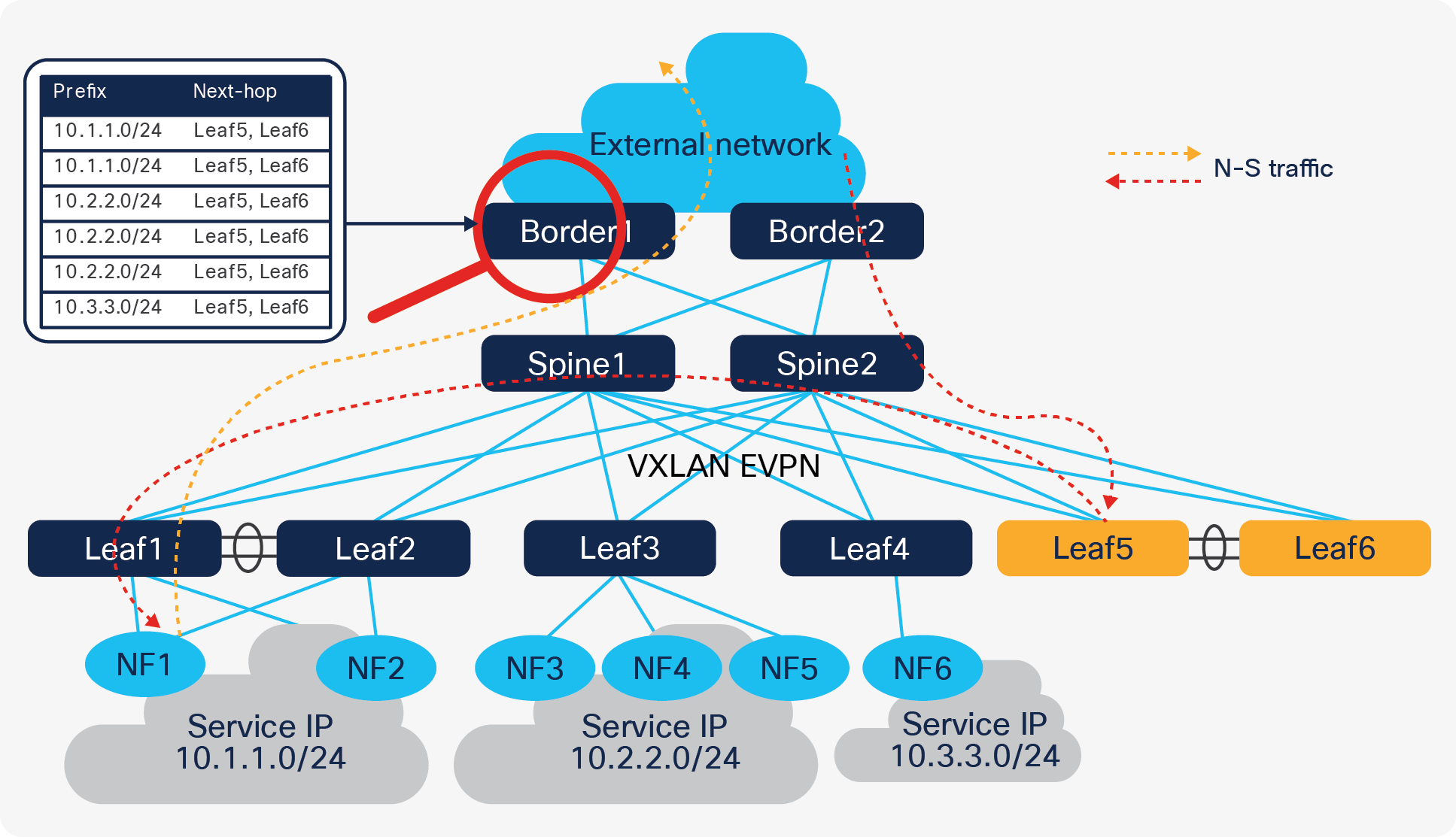
Problem with centralized routing peering
In the following section we discuss how Cisco VXLAN EVPN overcomes these challenges and optimizes traffic forwarding without tromboning, keeping the centralized BGP peering approach with the anchor leaf switches.
NF forwarding optimization:
Cisco NX-OS provides several tuning operations on the anchor leaf switches, spine switches, and the border switches to overcome the deficient routing tromboning while also achieving finer grained load-balancing. By enabling the extension of EVPN routes with additional information, we can flatten the “Service IP” routes from per leaf to per NF. The export-gateway-ip option introduced in Cisco NX-OS Release 9.3(5) adds an additional attribute called gateway address into EVPN type-5 advertisements. The gateway IP address is the origin of the prefix, and in case of a NF scenario, the gateway address will be filled in with the NF’s IP address. Hence by enabling this option, we are not just advertising the service IP to the border leaf, but alongside giving the gateway IP that gives information on how to get to the gateway IP.
Generally, this command adds the gateway address for all prefixes imported into the EVPN address family. If need be, to restrict the number of prefixes learned, we could use a route map to filter only the necessary prefixes that are learned from the NF nodes.
Example:
ip prefix-list vnf-subnet seq 10 permit <> le 32
ip prefix-list vnf-subnet seq 20 permit <> le 24
!
route-map export-gateway-ip permit 10
match ip address prefix-list vnf-subnet
set evpn gateway-ip use-nexthop
!
vrf context vnf_cluster
vni 50008
rd auto
address-family ipv4 unicast
route-target both auto
route-target both auto evpn
export map export-gateway-ip
Commands in the above example must be configured on all anchor leafs. Once a border receives the EVPN type-5 advertisement with the gateway address set, it picks up the gateway address as next-hop instead of origin, to update the RIB. The switch performs a recursive lookup to find the node’s correct VTEP to forward the packet.
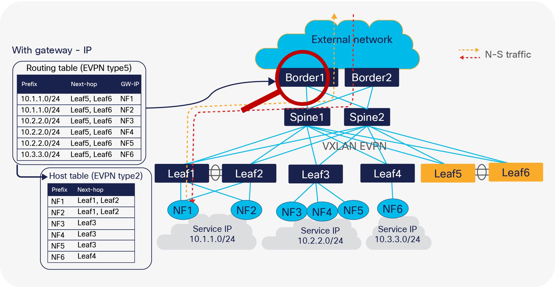
Optimized forwarding with recursive routing
Generally, the service subnet or IP is advertised from multiple nodes at the same time. As these advertisements look identical from an anchor leaf switch perspective when advertising to the EVPN address family, only one of the paths is selected by default. BGP does not evaluate the gateway IP address for a multipath decision. With proportional multipath, which was introduced in Cisco NX-OS Release 9.3(5), this problem is solved. The proportional multipath feature enables advertising of all the available next hops in the service network; this feature enables the switches to consider the gateway address of EVPN type-5 routes for ECMP and allows the traffic to be forwarded using all the available links stretched across multiple TOR switches.
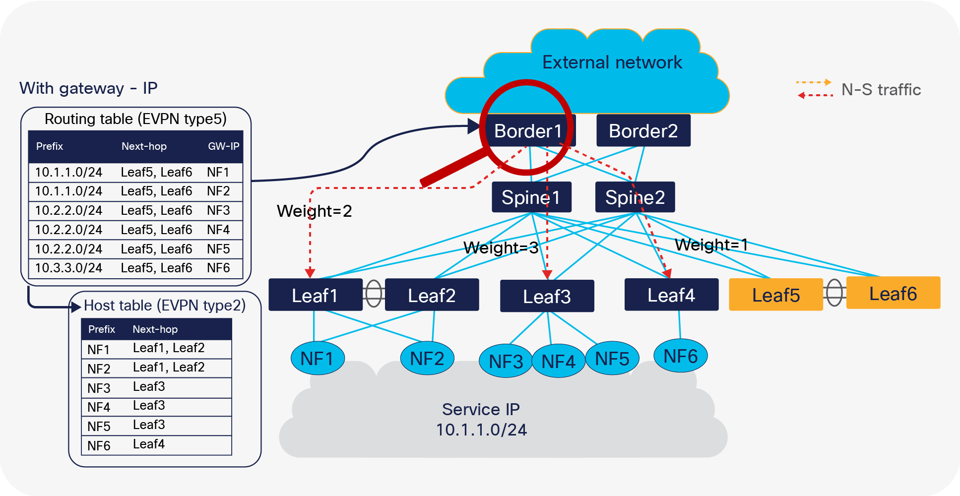
Proportional multipath for north-south traffic routing
In Figure 12, North-South traffic that enters the VXLAN EVPN fabric at border leaf is forwarded across all available NF nodes proportionately, based on the number of NF nodes connected to each of the leaf switches. This provides the most optimal load distribution by the VXLAN EVPN fabric extended with the proportional load balancing and export-gateway-ip functionality.
Additionally, mobility is not a problem if NF moves from leaf1/leaf2 to leaf3. A new type2 route update is sent, so subsequently the corresponding traffic follows the NF on the new leaf.
Here is an example of the configurations that must be applied to selected switches:
| Spine switches |
Anchor nodes and border |
| route-map add-path permit 10 set path-selection all advertise route-map extcon-rmap-filter deny 10 ! router bgp 65000 address-family l2vpn evpn maximum-paths ibgp 16 additional-paths send additional-paths receive additional-paths selection route-map add-path |
route-map add-path permit 10 set path-selection all advertise route-map extcon-rmap-filter deny 10 ! router bgp 65000 address-family l2vpn evpn maximum-paths ibgp 16 additional-paths send additional-paths receive additional-paths selection route-map add-path vrf vnf_cluster address-family ipv4 unicast export-gateway-ip advertise l2vpn evpn maximum-paths 16 maximum-paths ibgp 16 additional-paths send additional-paths receive additional-paths selection route-map add-path |
Example: Proportional multipath configurations
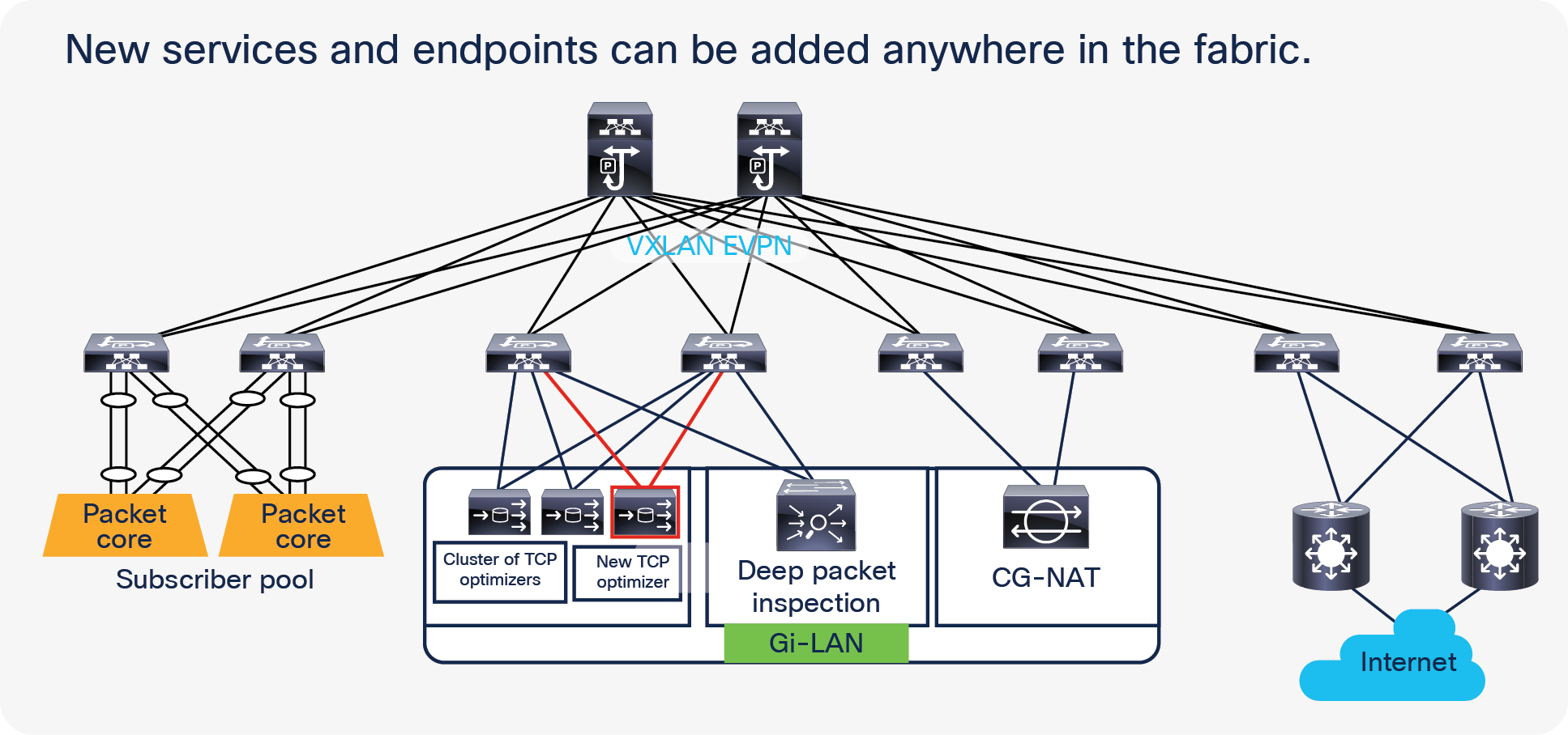
The Gi-LAN services block in the telco data center architecture offers enhanced security and value-added services for internet data traffic from mobile subscribers. Service functions such as Carrier-Grade Network Address Translation (CGNAT), firewall, parental control, URL filtering, Deep Packet Inspection (DPI), content optimization, etc., are leveraged to deliver a high-quality and secure data-service experience for subscribers.
Service chaining is a very common use case in Gi-LAN services block of telco data centers or telco cloud. Packets from telco servers such as PGWs need to be stitched or chained across multiple services such as TCP optimizers, Deep Packet Inspection (DPI), and Carrier-Grade NAT (CG-NAT) devices before they leave the data center.
Figure 13 shows a sample Gi-LAN services traffic flow.
The figure illustrates traffic steering through different service node types based on traffic type.
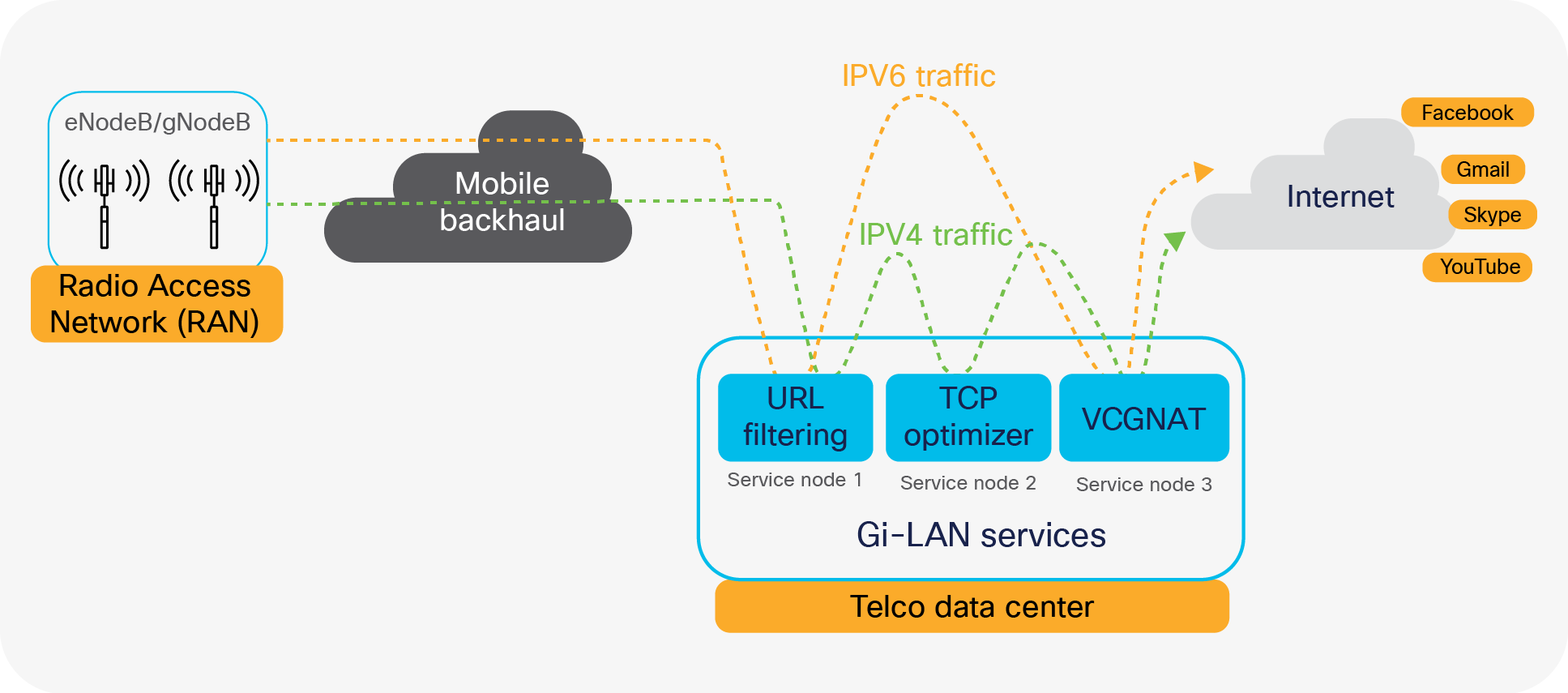
Gi-LAN services traffic flow
Enhanced Policy-Based Redirect (ePBR) overview
Enhanced Policy-Based Redirect (ePBR) service chaining and load-balancing capabilities together enable mobile network operators to flexibly insert and scale various network services in mobile packet core. With the introduction of ePBR, the entire service onboarding, service appliance monitoring using advanced probing mechanisms, selective traffic redirection, and load balancing are made flexible and easy to deploy. Listed below are some of the key benefits of ePBR:
● Simplified service appliance onboarding and service chain creation
● Optimized utilization of services through selective traffic redirection
● Ability to scale with symmetric load balancing capabilities
● Flexible health monitoring of service appliances and failover mechanisms
● Line-rate traffic forwarding with no impact on throughput and performance
Service chaining across the Telco data center
ePBR uses a combination of Policy-Based Routing (PBR) with customized, bucket-based load sharing to achieve its load-balancing and traffic-steering capabilities. Once the user defines a policy with service chaining and load-balancing rules, ePBR automatically creates multiple PBR policies and applies them on the service interface belonging to the service nodes, and also creates IP SLA–based probes to monitor the health of the service nodes.
Symmetry of traffic is a common need for services devices. The traffic from and into a data center should always go through the same node. ePBR ensures that symmetry is maintained for a given flow by making sure that traffic in both forward and reverse directions is redirected to the same service endpoint in the cluster.
End-to-end packet flow:
This section explains end-to-end packet flow for both forward and return traffic. Figure 14 shows how traffic from the subscriber pool is steered and distributed across service nodes before reaching the internet. The traffic is load-balanced first across a cluster of TCP optimizers and then service chained to DPI and CG-NAT devices, using ePBR.
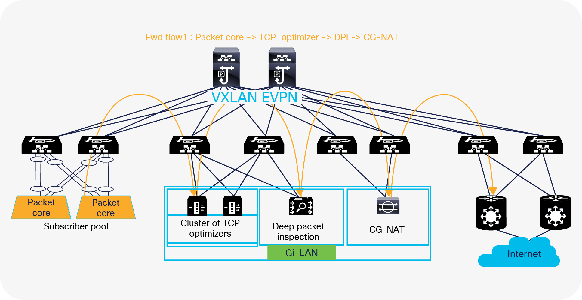
Forward flow - multinode service chain with NX-OS ePBR
Following is the packet flow sequence from NX-OS fabric to the internet:
1. ePBR policy on NX-OS matches with the source traffic received from the subscriber pool behind the packet gateway and the destination as the internet address.
2. Since a route-map with redirection rules is pre-programmed by ePBR, a match triggers a redirect action toward PBR node 1 (TCP optimizer cluster in this example).
3. Traffic is redirected to a specific service endpoint in the TCP optimizer cluster. ePBR load balances by using a bucket-based load-sharing algorithm with source or destination IP address. In the load-balance command, we provide the flexibility to the end user to specify the number of buckets, which allows the user to specify at what rate of granularity the traffic should be distributed.
4. After traffic is serviced by node 1, ePBR chains the traffic from node 1 to node 2 (DPI in this example) and consecutively toward the node 3 (CG-NAT) device.
5. CG-NAT instances do a source-NAT and forwards the traffic to the NX-OS fabric where traffic is permitted and forwarded to the internet.
Figure 15 shows an example of how the return traffic from the internet is steered and distributed across multiple service nodes before reaching its destination user-endpoints. On enabling the reverse policy, ePBR autogenerates reverse rules for return traffic. It reverses the order in which the traffic traverses the chain and reverses the Access Control List (ACL) matching the traffic.
Following is the packet flow sequence from the internet through an NX-OS fabric:
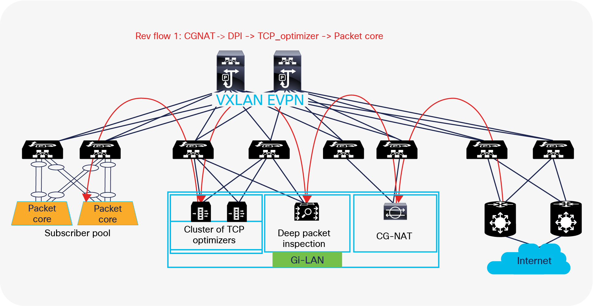
Reverse flow – multinode service chain with NX-OS ePBR
1. In the reverse path, traffic from the internet is routed directly to the CG-NAT instances by the NX-OS fabric, where the destination NAT translation happens and traffic is forwarded to the original user-endpoint address on to the NX-OS fabric.
2. Now ePBR policy matches the source as the internet address and the destination as the subscriber pool user endpoint address behind the packet gateway.
3. The ePBR policy match triggers a redirect action toward the Node-2 (the DPI device in this example).
4. Traffic after being serviced by the DPI device, once again matches the ePBR policy and is redirected toward node-1 (cluster of TCP optimizers) in this example.
5. Traffic is redirected to a specific service endpoint in the TCP optimizer cluster. Note that the traffic is served by the same TCP optimizer endpoint that serviced the forward packet for the flow, thereby maintaining traffic symmetry.
6. Finally, traffic, after being serviced by the TCP optimizer cluster, is permitted from there on and forwarded to the user endpoint.
Configuration example:
| Step 1: Onboard the appliances
epbr service tcp_optimizers vrf vrf_a ! traffic will be load-balanced between the optimizers ! optimizer1 service-end-point ip 110.1.1.2 interface Vlan110 probe icmp source-interface loopback0 reverse ip 150.1.1.2 interface Vlan150 probe icmp source-interface loopback1 ! optimizer2 service-end-point ip 110.1.1.3 interface Vlan110 probe icmp source-interface loopback0 reverse ip 150.1.1.3 interface Vlan150 probe icmp source-interface loopback1
epbr service DPI vrf vrf_a service-end-point ip 111.1.1.4 interface Vlan111 probe icmp source-interface loopback0 reverse ip 151.1.1.4 interface Vlan151 probe icmp source-interface loopback1
epbr service cg_nat vrf vrf_a service-interface Vlan20 probe http get index.html service-end-point ip 20.1.1.2 reverse ip 20.1.1.3
Step 2: Create traffic selection rules
ip access-list web 10 permit tcp 172.16.10.0/24 any eq www 20 permit tcp 192.168.20.0/24 any eq www IP access list exclude_traffic 10 permit tcp 172.16.10.10/32 any 20 permit tcp 172.16.10.11/32 any |
| Step3: Define ePBR traffic redirect policy In the policy defined below, Traffic destined to web-based application (filtered through ‘web’ ACL), will be service chained. Additionally, we exclude certain traffic flows from the service chain (filtered by ‘exclude_traffic’ ACL). In the event of TCP_optimizer cluster failure, the traffic is bypassed and is forwarded to the next element in the chain. In the event of DPI or CG_NAT service node failure, traffic is dropped.
epbr policy servicechain_and_loadbalance statistics match ip address exclude_traffic exclude match ip address web ! TCP optimizerDPIcg_nat chain 10 set service tcp_optimizers fail-action bypass 20 set service DPI fail-action drop 30 set service cg_nat fail-action drop
Step4: Apply the ePBR Policy on ingress interface connecting to the Packet gateway for forward traffic and apply policy with reverse keyword on egress interfaces connecting to the internet
interface Vlan30 ! Forward policy applied to ingress interface facing classifier no shutdown ip address 30.1.1.1/24 ipv6 address 2030::1/24 vrf member vrf_a epbr ip policy servicechain_and_loadbalance
interface Vlan40 ! Reverse policy applied to egress interface facing WAN for reverse flow no shutdown vrf member vrf_a ip address 40.1.1.1/24 ipv6 address 2040::1/24 epbr ip policy servicechain_and_loadbalance reverse
interface vlan100 ! L3vni interface on service leafs ip forward no ip redirect vrf member tenant_a epbr ip policy servicechain_and_loadbalance epbr ip policy servicechain_and_loadbalance reverse |
Health monitoring, flexible failover, and resilient hashing
ePBR provides a variety of probes (such as ICMP, TCP, UDP, HTTP, DNS, and user-defined custom probes) with flexible timers to periodically monitor the health of the service appliances.
In the case of a service reachability failure, ePBR provides the following fail-action mechanisms that can be leveraged to decide how traffic going to the failed service node needs to be handled.
a. Forward: default option where traffic should use the regular routing tables
b. Drop: traffic is dropped when service becomes unreachable.
c. Bypass: traffic is redirected to the next service sequence when there is a failure of the current sequence.
Additionally, ePBR also supports resilient hashing by revectoring the flows that were going to the failed service-endpoint to get re-hashed to the other active service endpoints in that service.
Figure 16 below illustrates how ePBR can bypass the TCP optimizer cluster in the event of a failure (ePBR detects the failure of a service node, using probes) and redirects the traffic to the next element in the chain, which is a DPI.
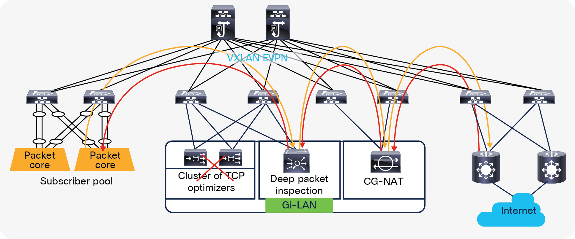
ePBR bypass service node capability
ePBR sessions enable users to make modifications to ePBR policy non-disruptively. Using this capability, we are able to onboard new service nodes efficiently and make modifications to existing service chains with minimal traffic disruption.
For example, if the TCP optimizer exceeds its capacity, customers can spawn a new TCP optimizer service in a scalable manner. Supporting this capability would just require the customer to onboard the new service endpoint onto ePBR, and all the redirection rules required for distributing the traffic will be automatically created, with zero-touch rebalancing.
ePBR simplified service node addition
Configuration example:
epbr session
! Add a new tcp_optimizer endpoint to the cluster
epbr service tcp_optimizers
service-end-point ip 130.1.1.2 interface Vlan130
probe icmp source-interface loopback0
reverse ip 160.1.1.2 interface Vlan160
probe icmp source-interface loopback1
commit
Distributed edge data center architecture
The current trend in telco data centers is to separate the user plane and the control plane. The control plane remains in central data centers, while the user plane is moving to edge data centers that are closer to subscribers. There are other services such as OTT caching and Gi-LAN that are moving to edge data centers, due to this trend in data center distribution.
Since telecom data centers are becoming distributed, there is a demand to have centralized management and consistent policy across any location. The Cisco NX-OS vision aligns with distributed telco data centers.
Cisco Nexus 9000 Series Switches with NX-OS enable telco operators to architect a distributed data center for edge, regional, and central data-center deployments. Leveraging VXLAN and BGP EVPN operators can build scalable fabrics, and using NDFC and NDO, operators can deploy services in any location in a distributed telco landscape and have them managed centrally with consistent policy control.
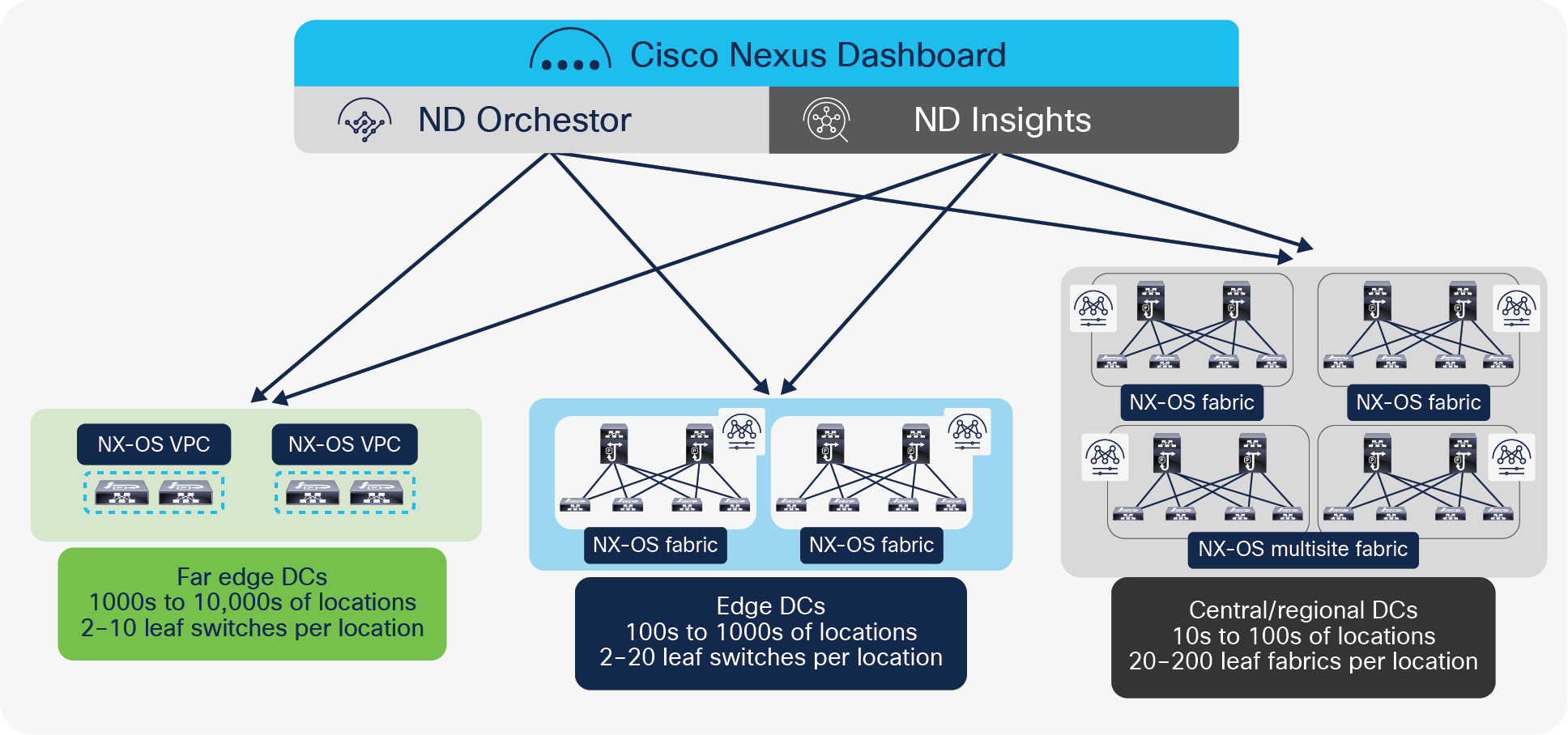
Edge, central, and regional data centers with NX-OS
Edge data center
The typical deployment of an edge data center consists of a pair of Cisco Nexus 9000 Series Switches configured as a vPC VTEP. vPC provides dual homing and offers redundancy.
Regional and central data centers
Regional and central data centers can host multiple services at scale. This requires an architecture to provide fault tolerance as well as the ability to horizontally scale.
Using VXLAN with BGP EVPN control plane, operators can build one or many fabrics within a site and multiple fabrics within a site can be managed by the same NDFC controller. Because operators want to have the ability to establish flexible inter-site network communications without jeopardizing change and fault domain isolations between those locations, NDFC acts as a controller for a given site, allowing customers to deploy and extend networks and VRFs across fabrics in that site (that is, they are enabled by placing all fabrics within a site in a specific NDFC Multi-site domain).
Cisco NX-OS border leafs connect to the perimeter transport network to the service provider core for routing to and from the edge and other locations in the telco landscape. For deployments involving multitenant networks, VRF-lite can be used to extend various VRF contexts between border leafs and the DC-PE core routers, as shown in Figure 18. Each VRF can use a dedicated physical or logical interface and routing protocol session to peer with the DC-PE routers.
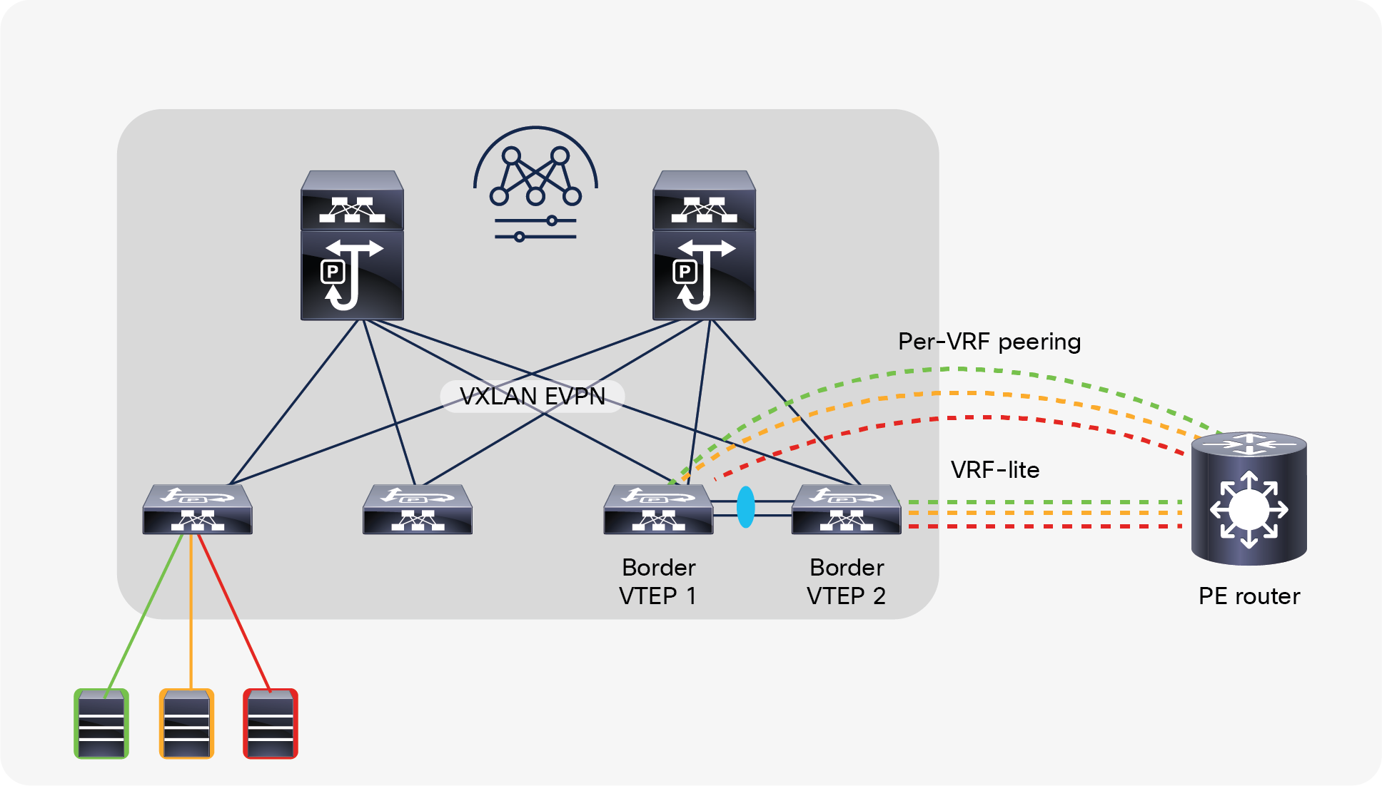
External Layer-3 connectivity – VRF-lite
NDFC automates the VRF-lite handoff workflow by providing an auto-configuration process that will configure automatically the VRF-lite on a border leaf node toward an external Layer-3 network. In NX-OS, VRF-lite is supported on border devices with the role of either border leaf node, border spine node, or border gateway node.
NX-OS SR-MPLS handoff
For large-scale deployments involving several VRFs extending to the core transport, configurations and operations become cumbersome, especially using VRF-lite with a large number of routing sessions. With the data center established on VXLAN EVPN and the core network requiring multitenant capable transport, there is a natural necessity for unified integration and handoff. To provide this seamless integration between different control-plane protocols and encapsulations (in this case from VXLAN to an MPLS-based core network), the Cisco Nexus 9000 Series Switch provides the border provider edge (border PE) capability by interfacing the data-center fabric and the core routers (provider routers or provider edge-routers).
The underlay routing protocol to connect a border device to an external fabric is ISIS or OSPF, and the overlay protocol is eBGP. The N-S traffic between the VXLAN fabric and the external fabric running SR-MPLS or MPLS LDP is supported. Additionally, instead of having per-VRF sessions between NX-OS and the core network, a single control-plane session (MP-BGP EVPN) is used for all VRFs.
The VXLAN to SR-MPLS handoff feature comprises the following configurations:
● Base SR-MPLS feature configuration
● Underlay configuration between the DCI handoff device and the device in the external fabric for the underlay connectivity. NDFC supports ISIS or OSPF as the routing protocol for the underlay connectivity.
● Overlay configuration between a DCI handoff device and a core or edge router in the external fabric, or another border device in another fabric. The connectivity is established through eBGP.
● VRF profile
Cisco NDFC supports the fully automatic deployment of this architecture with template policies, border versioning checks, and configuration profiles, which, to a large extent, simplifies and unifies the NX-OS-to-core transport connectivity design.
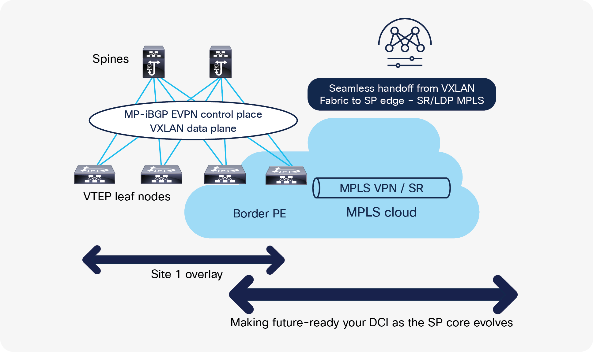
Seamless handoff from VXLAN to SP Edge
Operational simplification with NDFC and NDI
Scale and complexity in data centers are growing. To simplify operations, Cisco NDFC has multiple tools that help users to proactively find faults, troubleshoot, and perform regular operations on the network. When combined with Cisco’s Nexus Dashboard Insights (NDI), customers can complement their solution with advanced support for day-2 operations.
The reader can refer to the sections below to get more details about the operational benefits of using Cisco NDFC and NDI.
With a multilayer topology view, NDFC stitches together various multitude of information to enable a real-time topology view of the network, health checking, and operations in a single window. It shows us a combination of physical and logical network topologies with information on the protocol states running between devices. Furthermore, a network operator can view and compare a fabric based on operation health and configuration compliance.
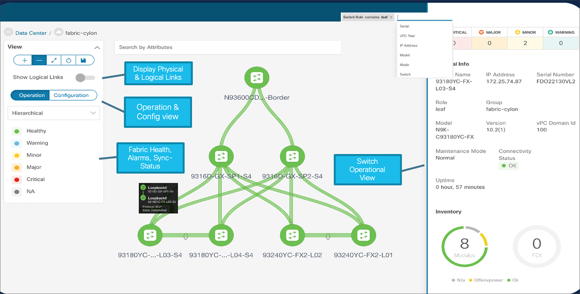
Real-time network view with NDFC
The real-time network view maximizes details about individual switches such as hardware type, software version, existing and past alarms, device roles, connectivity status, etc. NDFC enables Real-time topology searches based on dynamic attributes. Accordingly, using the match criteria, NDFC displays the dynamic topology.
Configuration Compliance (CC) functionality ensures that the intended configurations as expressed by those CLIs are present on the switches and if they are removed or if there is a mismatch, then CC flags it and indicates that the device is Out-of-Sync. Configuration compliance marks a specific switch as out-of-sync when the intent does not match running configuration.
If a specific fabric is out of sync according to configuration management, it will be flagged in red in the topology view. A healthy fabric is indicated in green. CC is performed by default by NDFC every 60 minutes.
CC checks can also be user driven, with the following options:
● Recalculate and deploy
● Preview and deploy
● Resync
If an out-of-compliance condition is detected in the underlay (VTEP), overlay (network), or access layer, the system sends alerts and builds a diff-set to restore compliance with the current policy settings. Remediation can be applied when necessary. Currently, auto-remediation is not supported, since this can cause problems for customers who apply manual configuration on the box temporarily during troubleshooting.
The applied policy can be changed for the whole fabric if required or the specific diff-set can be deployed to restore consistency (compliance).
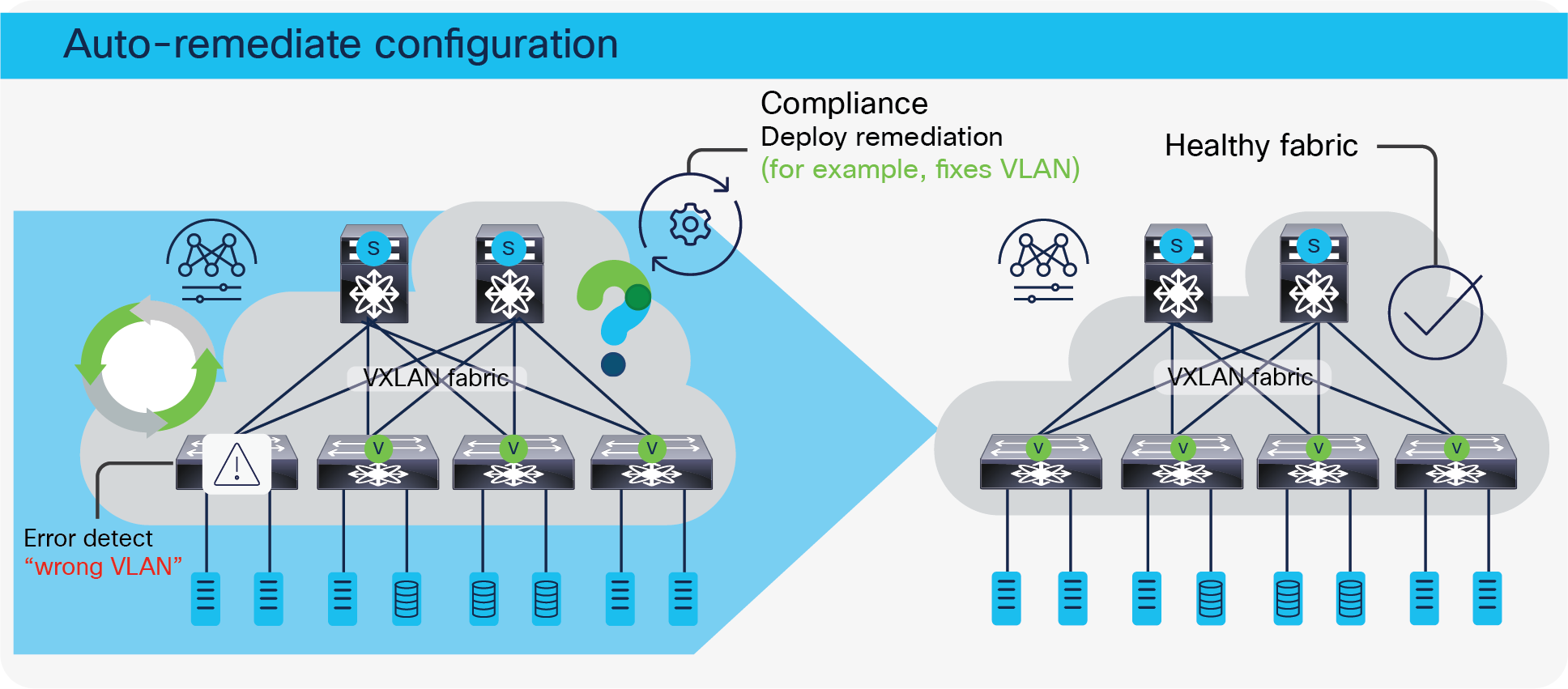
NDFC configuration compliance
Virtual Machine Manager visualizer
Along with physical network infrastructure, NDFC provides full visibility into virtual infrastructure with VMM integration. Operators can visualize complete topology from virtual machines to physical uplink switches.
This feature allows the following functionalities:
● Discover the network objects in the VMware vCenter
● Discover the connectivity between servers (vSwitches/DVS’s) and Cisco Nexus switches imported into NDFC
● Obtain details on VMs, providing visibility into guest OS’s, specifications, uplink vNICs, vSwitches, ESXi hosts, and connections to the rest of the physical network
● Search filters using port group names, vSwitches, host names, connectivity status, and many more terms are also provided.
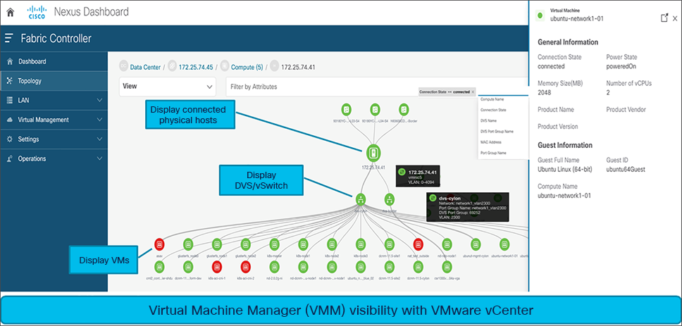
NDFC Virtual Machine Manager
Additionally, NDFC also supports Kubernetes (K8s) visualization. It displays the topology including the pods running in name spaces for VM-based Kubernetes clusters managed by vCenter and Kubernetes installed on bare-metal directly connected to the switch.
The Kubernetes overview provides summarized data such as vCenter IP address, status of vCenter, fabric associated with the cluster, switch name, switch IP, switch Port, VPC ID, compute node, and physical NIC. Each Kubernetes cluster node additionally displays the associated Kubernetes cluster resources, such as compute nodes and pods.
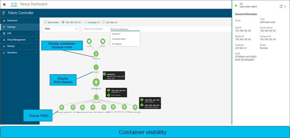
NDFC container visibility
Endpoint Location monitoring across multiple fabrics
The Endpoint Locator (EPL) feature allows real-time tracking of endpoints within a data center. The tracking includes tracing the network life history of an endpoint and getting insights into the trends that are associated with endpoint additions, removals, moves, and so on. An endpoint is anything with at least one IP address (IPv4 and\or IPv6) and MAC address.
EPL relies on BGP updates to track endpoint information and NX-API to provide additional information about endpoints. Hence, typically the NDFC needs to peer with the BGP Route-Reflector (RR) to get these updates. For this purpose, IP reachability from the NDFC to the RR is required. This can be achieved over in-band network connection to the NDFC eth2 interface.
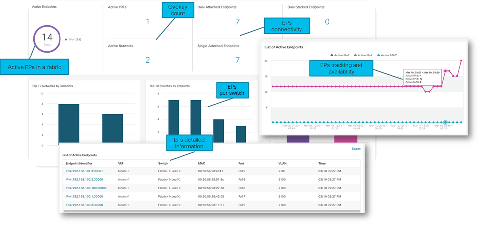
NDFC endpoint locator
NDFC EPL supports real-time and historical search for all endpoints across various search filters, such as VRF, network, Layer-2 VNI, Layer-3 VNI, switch, IP, MAC, port, VLAN, and so on. Additionally, NDFC EPL also supports real-time and historical dashboards for insights such as endpoint lifetime, network, endpoint, VRF daily views, and operational heat map.
Simplified Cisco NX-OS Software upgrades using NDFC
With simplified Cisco NX-OS Software upgrades powered through NDFC, an operator can perform 80 percent of tasks prior to a maintenance window by decoupling pre-upgrade steps such as staging and validating images prior to the actual upgrade window. Later on, image policy can be applied to a set of switches for upgrades or downgrades, application of RPM patches, EPLD image upgrades, Software Maintenance Updates (SMUs), and more.
During initiation of the upgrade process, NDFC automatically isolates the concerned switch from the network using Graceful Insertion and Removal (GIR), so network traffic is not attracted towards the isolated switch during upgrade process.
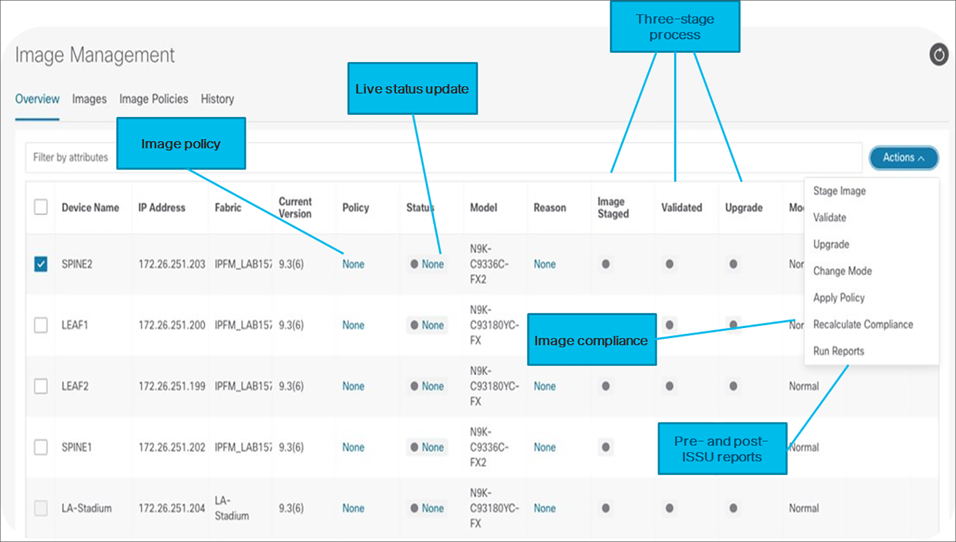
NDFC image management
Operators can compare pre- and post-ISSU programmable reports on upgrades to visualize current and future network and operational states during a maintenance window. The Automatic image compliance policy maintains the switches to be compliant and in sync with the image policies applied in the fabric.
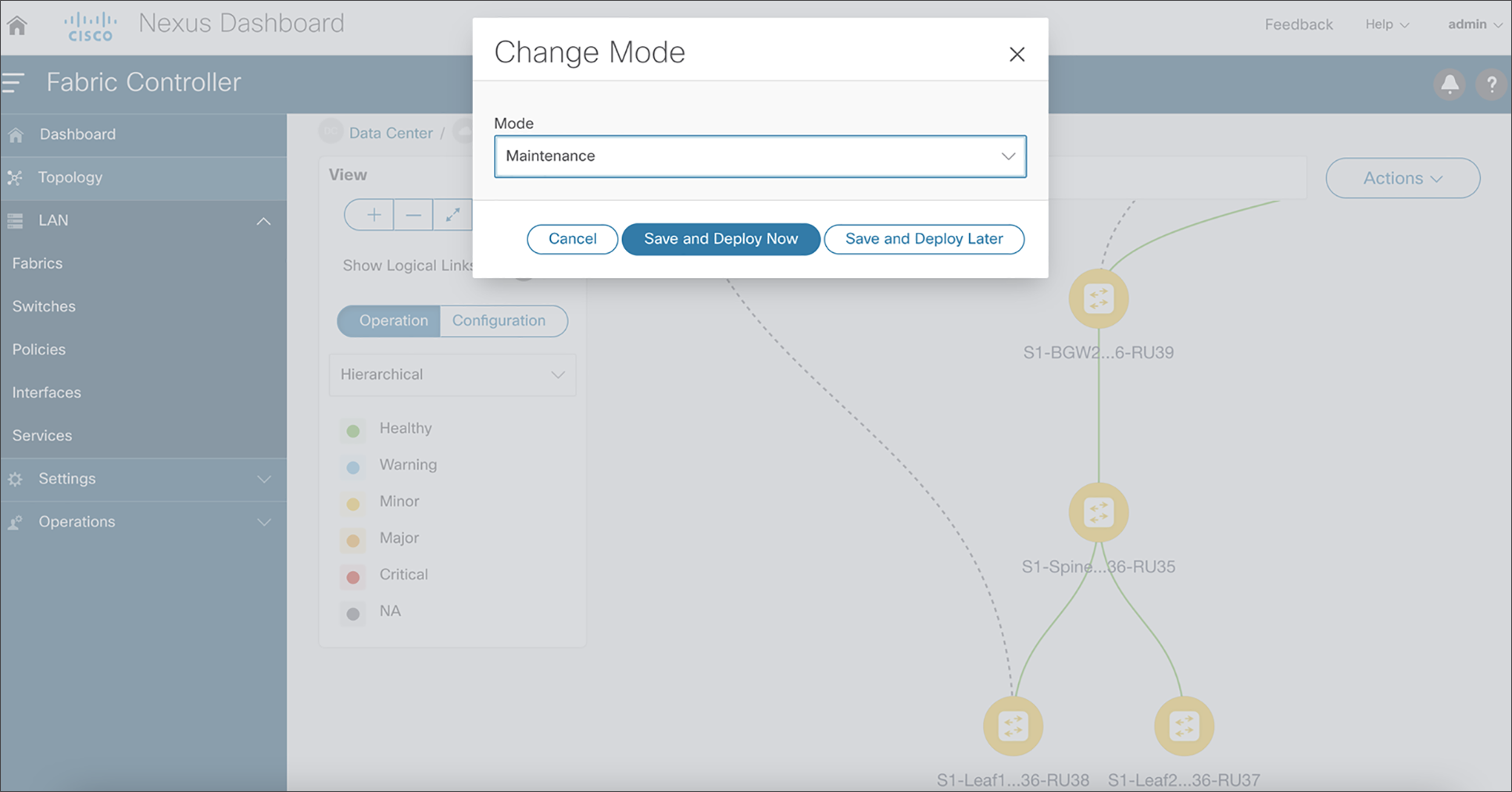
NDFC supports consistent porting of underlay and overlay configurations to a new switch when the RMA workflow is triggered for a faulty switch. A complicated process such as a switch RMA and replacement requires only a few clicks (with no manual configuration changes), as listed below. The following steps elaborate on the actual RMA workflow from NDFC.
7. Put the device in maintenance mode.
8. Physically replace the device in the network.
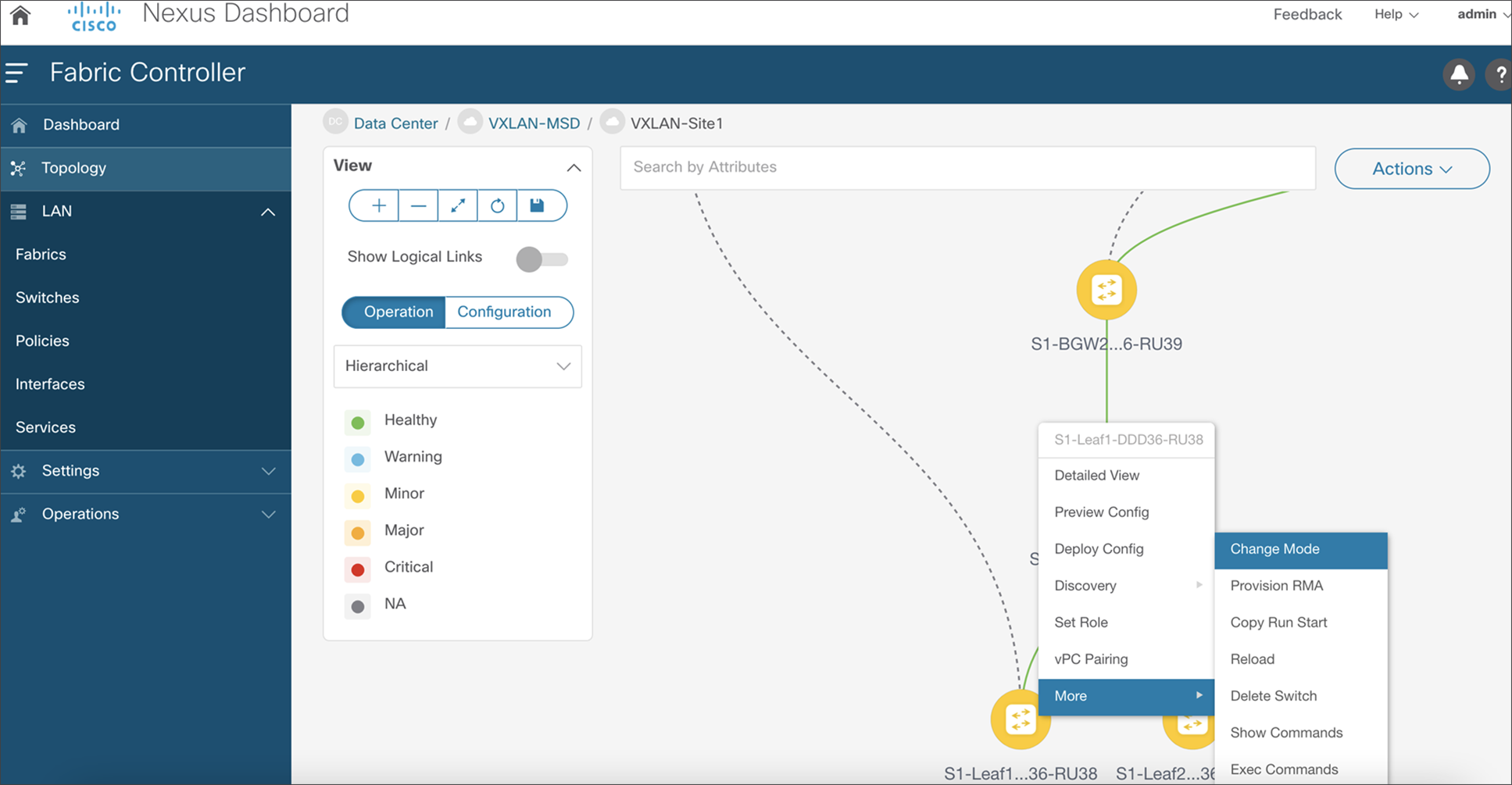
NDFC RMA workflow
9. Choose the Provision RMA option and select the replacement device.
10. NDFC will automatically perform Power-On Auto Provisioning (POAP) on the device with the expected configuration for the node.
11. Once the new device is online, move the device back into Normal Mode.
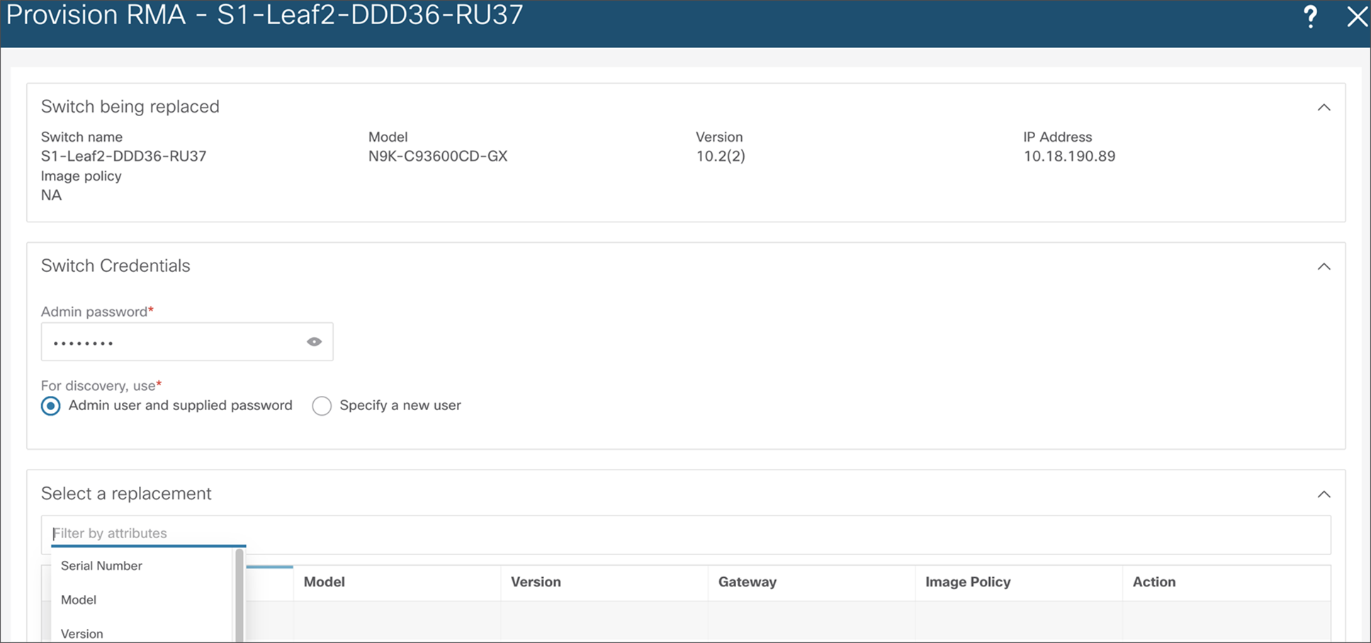
NDFC RMA workflow – replace a switch
The VXLAN OAM tools (namely ping, pathtrace, and traceroute) provide reachability information to the various hosts and VTEPs in a VXLAN network. VXLAN OAM can be enabled from NDFC to show the details such as reachability and actual path of flows in a VXLAN EVPN–based fabric. The following use cases are supported through NDFC for VXLAN OAM:
● The switch-to-switch option provides the VXLAN OAM ping and traceroute test results for the VTEP-to-VTEP use-case.
● The host-to-host option provides the VXLAN OAM pathtrace results for the exact path that is taken by a given flow from the VTEP or switch that is connected to the source host to the VTEP or switch that is connected to the destination host.
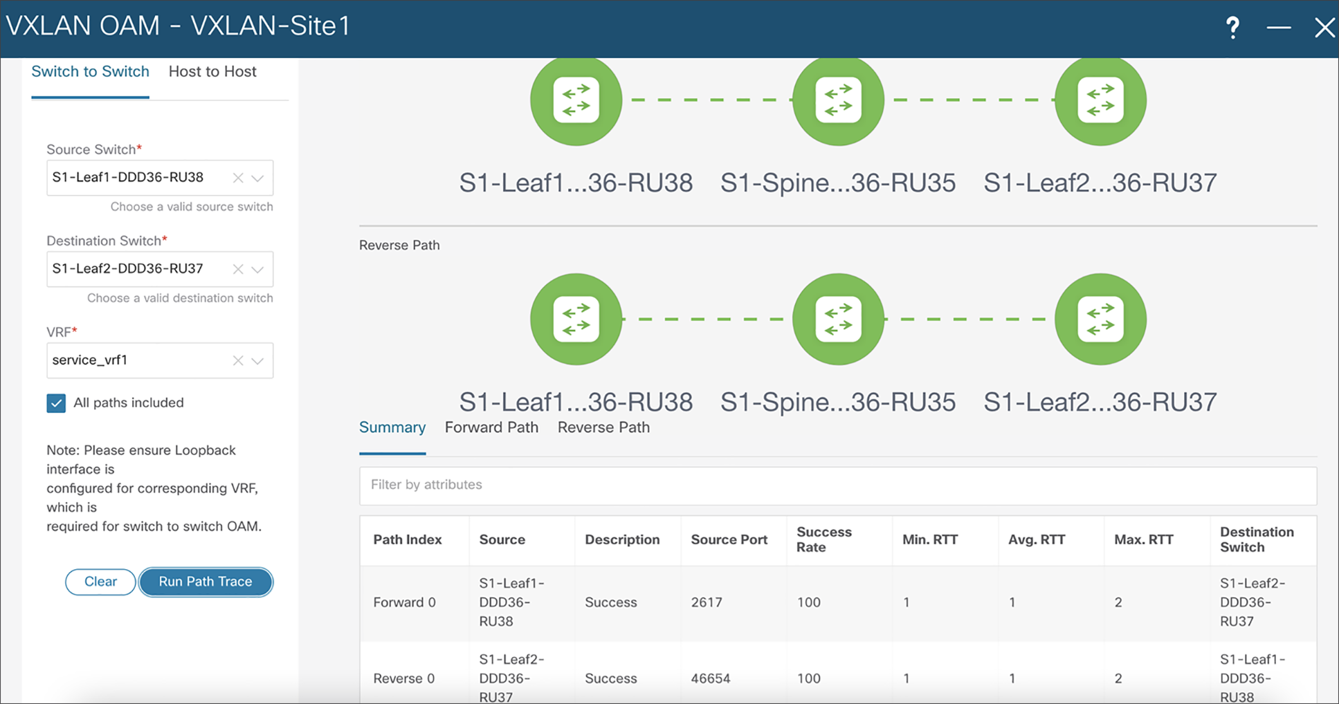
NDFC VXLAN OAM tool
Day-2 operations with Cisco Nexus Dashboard Insights
Cisco Nexus Dashboard Insights (NDI) is a unified monitoring and analytics tool that helps with day-2 operations for NDFC network sites hosted on Cisco Nexus Dashboard. NDI provides deeper visibility and insights into both the network and application layers by providing comprehensive visibility into the infrastructure. NDI uses flow telemetry data (flow records and respective counters) from NX-OS switches and correlates this data over a time period to provide end-to-end flow path and latency. The NX-OS ASICs that are used have the capability to support hardware telemetry information by capturing full data-plane packet information at line rates, which NDI, in turn, leverages to provide meaningful insights.
Cisco NDI provides the following operational benefits in a 5G-powered, telco data center:
● NDI increases network availability and prevents outages for businesses with proactive notifications covering security advisories, critical bugs, end-of-life and end-of-support announcements, recommended software and hardware upgrades based on platforms, deployed software, and other features.
● NDI shortens the Mean Time To Resolution (MTTR) of network issues for telco operators and saves operational costs through automated root-cause analysis of data-plane anomalies, such as packet drops, latency, workload movements, routing issues, ACL drops, etc.
● NDI increases speed and agility for capacity planning by highlighting various components that exceed capacity and thresholds, and helps network operators plan for resizing, restructuring, and repurposing.
● NDI enables faster troubleshooting by collecting logs that can be attached to a Cisco Technical Assistance Center (TAC) case.
Listed below are sample NF use cases relevant in a telco data center.
Anomalies for BGP flaps and route advertisement
Figure 30 shows how NDI can identify and flag anomalies when BGP received prefix count from a NF decreased from its original value. Similarly, any BGP session state changes peering with the NFs are identified and flagged as anomalies.
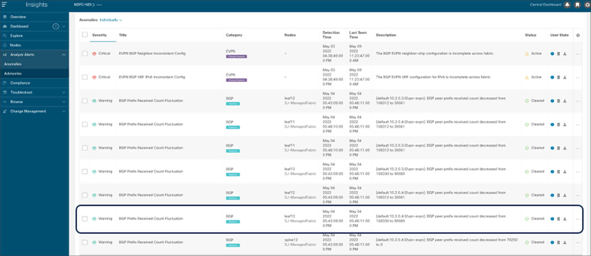
NDI BGP prefix received count fluctuation anomaly
Packet drop notifications
For specific flows of traffic in our data center, NDI identifies packet drops and flags them as anomalies in the NDI dashboard.
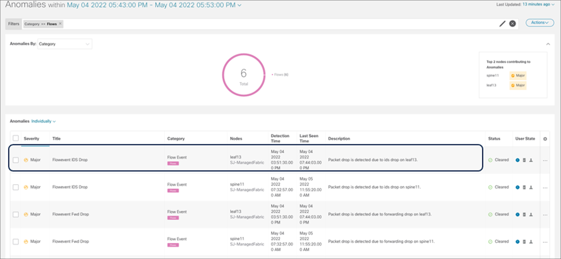
NDI flow event packet drop anomaly
Event correlations:
Additionally, NDI correlates different events to provide meaningful insights. For example, the packet drop anomaly is root caused below by NDI due to the BGP prefix count fluctuation.
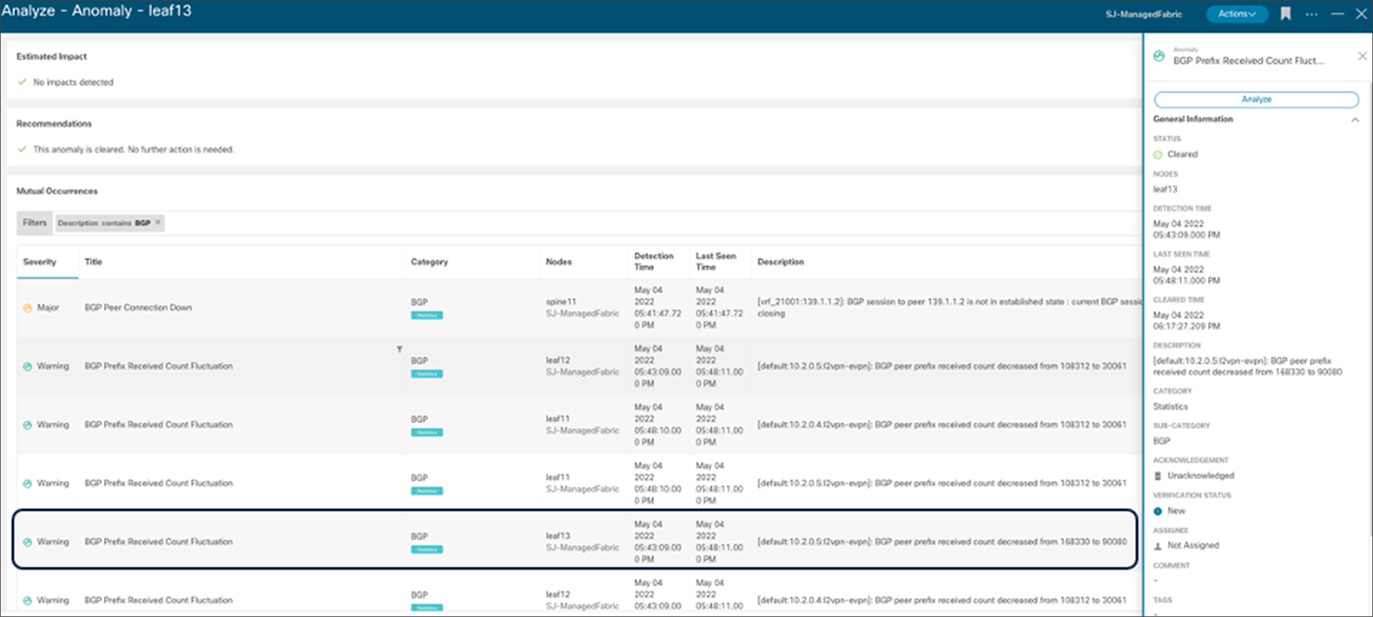
NDI Analyze Anomaly - mutual occurrences
Cisco NX-OS with NDFC provides a great solution for building a distributed telecom data center that provides consistent policy, automation, and operations for all data centers, including edge, regional, and central data centers. Specific capabilities, such as connectivity to packet core, service chaining, and SR/MPLS handoffs, make Cisco NX-OS a perfect choice to build a 5G-ready telco data center. Cisco NDFC along with NDI provides E2E service automation, orchestration, and day-2 operations for 5G service providers looking to simplify operations. Cisco NX-OS and NDFC together, help to architect agile, flexible, and efficient data centers, enabling service providers to develop and deploy new services easily and effectively.
NDFC configuration guide: https://www.cisco.com/c/en/us/td/docs/dcn/ndfc/1201/configuration/fabric-controller/cisco-ndfc-fabric-controller-configuration-guide-1201.html
VXLAN EVPN configuration guide: https://www.cisco.com/c/en/us/td/docs/dcn/nx-os/nexus9000/102x/configuration/vxlan/cisco-nexus-9000-series-nx-os-vxlan-configuration-guide-release-102x/m-configuring-seamless-integration-of-evpn-with-l3vpn-srv6-93x.html
Proportional multipath feature reference: https://www.cisco.com/c/en/us/td/docs/dcn/nx-os/nexus9000/102x/configuration/vxlan/cisco-nexus-9000-series-nx-os-vxlan-configuration-guide-release-102x/m_configuring_proportional_multipath_for_vnf.html
ePBR for service chaining White Paper: https://www.cisco.com/c/en/us/products/collateral/switches/nexus-9000-series-switches/layer4-layer7-service-redir-ply-based-redir-wp.html
NDFC Border Provisioning: https://www.cisco.com/c/en/us/td/docs/switches/datacenter/sw/11_3_1/config_guide/lanfabric/b_dcnm_fabric_lan/border-provisioning-mpls.pdf
NDFC NDI integration guide: https://www.cisco.com/c/en/us/td/docs/dcn/whitepapers/getting-ndfc-network-sites-ready-for-nexus-dashboard-insights.html
Container networking: https://www.cisco.com/c/en/us/td/docs/dcn/whitepapers/cisco-nx-os-calico-network-design.html
NDO NDFC design guide: https://www.cisco.com/c/en/us/td/docs/dcn/whitepapers/automating-data-center-architecture-with-ndo-and-ndfc.html