Overview
The Cisco VG248 Analog Phone Gateway (VG248) enables you to connect analog telephones, modems, and fax machines to the Cisco CallManager IP telephony system.
These sections provide an overview of the VG248:
Introduction
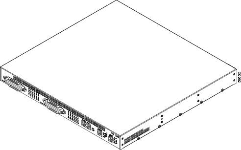
The VG248 is a 19-inch rack-mountable hardware device. It includes 48 FXS port interfaces to connect directly to standard analog telephones, modems, or fax machines. The analog devices connected through the FXS port behave as if they are connected to a normal central office (CO) or PBX line, supporting features such as call waiting, caller ID, call transfer, and call transfer.
The VG248 also includes a 10/100 Mbps Ethernet port interface to connect to the Ethernet network for connectivity to Cisco CallManager and the IP telephony network.
Figure 1-1 provides an overview of the entire device.
Figure 1-1 VG248 Overview
These sections provide additional detail about the VG248 and its interfaces:
Front Panel
Figure 1-2 provides an overview of the interfaces and LED displays on the front panel of the VG248.
Figure 1-2 VG248 Front Panel
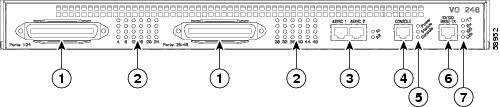
FXS Telco Connectors
The FXS interface consists of two telco (RJ-21) connectors featuring these characteristics:
•![]() On-premise connections only—analog phones must be physically located in the same building as the VG248.
On-premise connections only—analog phones must be physically located in the same building as the VG248.
•![]() Maximum supported line length—5000 feet or 415 Ohms.
Maximum supported line length—5000 feet or 415 Ohms.
•![]() Loop start support
Loop start support
•![]() Support for disconnect supervision
Support for disconnect supervision
•![]() DTMF dialing
DTMF dialing
•![]() Maximum ringer equivalency number (REN) load—3 per line, and only two phones per line can be off-hook at any one time
Maximum ringer equivalency number (REN) load—3 per line, and only two phones per line can be off-hook at any one time
•![]() Voice activity detection
Voice activity detection
•![]() Supported codecs—G.711 and G.729a codecs; the same codec must be used for both directions.
Supported codecs—G.711 and G.729a codecs; the same codec must be used for both directions.
Table 1-1 describes the FXS connector pinouts for ports 1-24.
Table 1-2 describes the FXS connector pinouts for ports 25-48.
Status Indicators
Three sets of status indicator LEDs on the front panel display the VG248 status:
Table 1-3 includes descriptions of the LED states of these status indicators.
Console Port
Use the console port to connect the VG248 to a console terminal for configuration and management tasks. Table 1-4 describes the console port connector pinouts.
|
|
|
|---|---|
1, 8 |
Connected to each other |
2 |
DTR |
3 |
TxD |
4,5 |
Ground |
6 |
RxD |
7 |
DSR |
Ethernet Port
Use the Ethernet port to connect the VG 248 to the IP network to access Cisco CallManager. Table 1-5 describes the Ethernet port connector pinouts.
|
|
|
|---|---|
1 |
TD+ |
2 |
TD- |
3 |
RD+ |
4 |
— |
5 |
— |
6 |
RD- |
7 |
— |
8 |
— |
Rear Panel
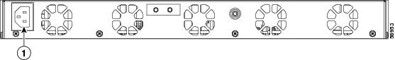
The rear panel of the VG248 includes the power connector (see Figure 1-3). The VG248 has a single AC inlet requiring 100- 240 VAC, 50-60 Hz. The VG248 draws approximately 176W at 100v in its maximum load condition.
Figure 1-3 VG248 Rear Panel
|
|
Power connector |
 Feedback