-
Cisco Unified Wireless IP Phone 7920 Administration Guide for Cisco Unified CallManager Releases 4.2 and 5.0 (SCCP)
-
Preface
-
An Overview of the Cisco Unified Wireless IP Phone 7920
-
An Overview of the Wireless Network
-
Setting Up Cisco Unified Wireless IP Phones
-
Using the Cisco 7920 Configuration Utility
-
Configuring Network Profiles on the Cisco Unified Wireless IP Phone 7920
-
Verifying the Wireless Network Configuration on the Cisco Unified Wireless IP Phone
-
Configuring Features, Templates, Services, and Users
-
Viewing Status, Statistics, and Firmware Information on the Cisco Unified Wireless IP Phone 7920
-
Monitoring the Cisco Unified Wireless IP Phone Remotely
-
Troubleshooting the Cisco Unified Wireless IP Phone 7920
-
Providing Information to Users By Using a Website
-
Supporting International Users
-
Physical and Operating Environment Specifications
-
Index
-
 Feedback
Table Of Contents
Setting Up Cisco Unified Wireless IP Phones
Methods for Adding Phones to Cisco Unified CallManager
Adding Phones with Auto-Registration
Adding Phones with Auto-Registration and TAPS
Adding Phones with Cisco Unified CallManager Administration
Installing the Cisco Unified Wireless IP Phone 7920
Providing Power to the Cisco Unified IP Phone
Installing or Removing the Phone Battery
Powering On the Wireless IP Phone 7920
Active and Standby Phone Modes
Startup Settings for a Network Without DHCP
Audio Quality Subjective to the User
Configuring the Ring Tone to the Headset
Using External Devices with Your Cisco Unified IP Phone
Setting Up Cisco Unified Wireless IP Phones
This chapter includes the following topics, which help you install and configure the Cisco Unified Wireless IP Phone 7920 on an IP telephony network:
•
Installing the Cisco Unified Wireless IP Phone 7920
Before You Begin
Before installing a Cisco Unified Wireless IP Phone 7920, review the requirements in these sections:
•
Network Requirements
For the Cisco Unified Wireless IP Phone 7920 to successfully operate as a Cisco Unified IP Phone endpoint, your network must meet the following requirements:
•
–
–
•
•
–
–
Note
Related Topics
•
•
•
Methods for Adding Phones to Cisco Unified CallManager
Before installing the Cisco Unified Wireless IP Phone, you must choose a method for adding phones to the Cisco Unified CallManager database. Some methods require entering the media access control (MAC) address of the phone. Table 3-1 provides an overview of these methods.
The following sections describe these methods:
•
•
•
Adding Phones with Auto-Registration
You can use auto-registration to quickly enter phones into the Cisco Unified CallManager database without first gathering MAC addresses from the phones.
When auto-registration is enabled, Cisco Unified CallManager begins the automatic startup process to obtain a directory number. During auto-registration, Cisco Unified CallManager automatically assigns the next available sequential directory number to new phones as they register with Cisco Unified CallManager.
After registering phones with Cisco Unified CallManager, you can modify any settings, such as the directory numbers, by using Cisco Unified CallManager Administration. Additionally, you can move auto-registered phones to new locations and assign them to different device pools without affecting their directory numbers.
Auto-registration is disabled by default in Cisco Unified CallManager. You must enable and properly configure auto-registration before connecting any Cisco Unified IP Phone to the network. For information about enabling and configuring auto-registration, refer to Cisco Unified CallManager Administration Guide.
Adding Phones with Auto-Registration and TAPS
You can add a group of phones quickly by using auto-registration and TAPS. First, use the Bulk Administration Tool (BAT) to add phones to the Cisco Unified CallManager database with dummy MAC addresses. Then use TAPS to update MAC addresses and download pre-defined configurations for the phones.
To implement TAPS, you or the end-users dial a TAPS directory number and follow voice prompts. When the process is complete, the phone has downloaded its directory number and other settings. The correct MAC address for the phone is updated in Cisco Unified CallManager Administration.
You must make sure that auto-registration is enabled in Cisco Unified CallManager Administration for TAPS to function.
Refer to Bulk Administration Tool User Guide for Cisco Unified CallManager for detailed instructions about BAT and about TAPS.
Related Topics
•
•
Adding Phones with BAT
When you must add several phones at the same time to the Cisco Unified CallManager database, you can use BAT. This plug-in application for Cisco Unified CallManager enables you to perform batch operations, including registration, on multiple phones.
To add phones using BAT only (not in conjunction with TAPS), you first must obtain the appropriate MAC address for each phone.
Determining the MAC Address of a Cisco Unified IP Phone
When adding phones to the Cisco Unified CallManager database using Cisco Unified CallManager Administration or using BAT, you must enter the media access control (MAC) address of the phone. Table 3-2 describes how to determine the MAC address of the Cisco Unified Wireless IP Phone.
Table 3-2 Determining the MAC Address of the Phone
Choose Menu > Network Config > MAC Address and look at the MAC Address field
See Chapter 5 "Configuring Network Profiles on the Cisco Unified Wireless IP Phone 7920"
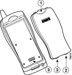
Remove the battery and look on the back of the phone.
For detailed instructions about using BAT, refer to Cisco Unified CallManager Administration Guide and to Bulk Administration Tool Guide for Cisco Unified CallManager.
Note
Related Topics
•
•
•
Adding Phones with Cisco Unified CallManager Administration
You can add phones individually to the Cisco Unified CallManager database using Cisco Unified CallManager Administration. To do so, you first must obtain the MAC address for each phone. See the "Methods for Adding Phones to Cisco Unified CallManager" section for instructions.
After you have collected MAC addresses, choose Device > Add a New Device in Cisco Unified CallManager Administration to begin.
For additional instructions and conceptual information about Cisco Unified CallManager, refer to Cisco Unified CallManager Administration Guide and to Cisco Unified CallManager System Guide.
Related Topics
•
•
Safety Information
Review the following warnings before installing the Cisco Unified IP Phone. To see translations of these warnings, refer to the Regulatory Compliance and Safety Information for the Cisco Unified Wireless IP Phone 7920 document that accompanied this device.
Warning
Warning
Warning
WarningBattery Safety Notices
These battery safety notices apply to the batteries that are approved by the Cisco Unified Wireless IP Phone 7920 manufacturer.
Warning
Caution
Caution
Caution
Caution
Caution
Caution
Caution
To obtain a replacement battery, contact your local dealer. Use only the batteries that have a Cisco part number.
Standard battery—CP-BATT-7920-STD
Extended battery—CP-BATT-7920-EXT
Caution
North America—CP-PWR-7920-NA
Central Europe—CP-PWR-7920-CE
United Kingdom—CP-PWR-7920-UK
China—CP-PWR-7920-CN
Japan—CP-PWR-7920-JP
To see translations of the warnings that appear in this publication, refer to the Regulatory Compliance and Safety Information for the Cisco Unified Wireless IP Phone 7920 document that accompanied this product.
Related Topics
•
Installing the Cisco Unified Wireless IP Phone 7920
After setting up the wireless network to support voice communications and configuring the Cisco Unified Wireless IP Phones in Cisco Unified CallManager, you are ready to install the phones. This section includes the following installation information.
•
•
Providing Power to the Cisco Unified IP Phone
The Cisco Unified Wireless IP Phone 7920 uses a battery for power. Table 3-3 describes the types of batteries available for the Cisco Unified Wireless IP Phone and the maximum talk and standby times.
Table 3-3 Batteries Available for the Cisco Unified Wireless IP Phone 7920
Standard
Lithium-ion
3.5 hr
21 hr
Extended
Lithium-ion
4.25 hr
30 hr
The following sections provide information about the battery:
•
Installing or Removing the Phone Battery
To install the battery in the Cisco Unified Wireless IP Phone, follow these steps. See Figure 3-1 for a graphical overview of these steps.
Procedure
Step 1
Step 2
Step 3
Figure 3-1 Cisco Unified Wireless IP Phone 7920 Battery Installation
Note
Charging the Battery
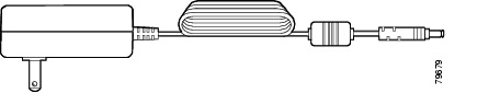
To charge your battery quickly, use the AC adapter shown in Figure 3-2. Plug the AC adapter into a wall outlet, and insert the connector into the base of your Cisco Unified Wireless IP Phone 7920 or to the back of the desktop charger. You can use the phone while the battery is being charged.
Figure 3-2 Power Supply
Table 3-4 shows the charging time for the two types of batteries. Check the charging status on the phone display or on the front of the desktop charger. You can stop charging the battery when the battery is fully charged, and you can leave the batteries in the charger for extended time periods with no ill effects. Lithium ion batteries can be partially charged without shortening the battery life, because they have no memory. Batteries should handle up to 4000 recharges.
Table 3-4 Charging Time Information
Connected to PhoneStandard
3.5 hr
6 hr
Extended
4.5 hr
8.5 hr
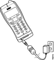
To charge the Lithium ion battery, follow these steps:
Procedure
Step 1
Step 2
If the phone is turned off, the screen displays the message, "Battery Charging." When the battery is charged, "Battery Full" displays.
If the phone is turned on, the battery indicator bar blinks, displaying the current power level. When the battery is charged, the indicator bar stops blinking, and "Charging Complete" displays.
Step 3
Figure 3-3 Charging the Phone Battery
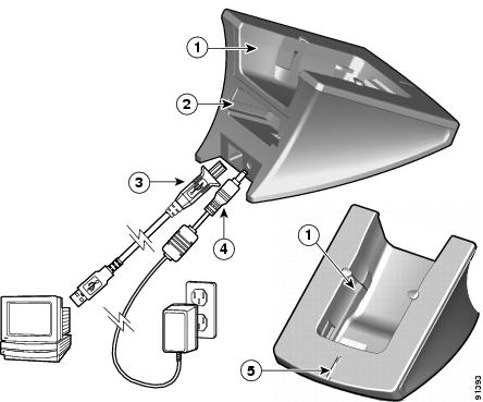
Using the Desktop Charger
The desktop charger, shown in Figure 3-4, can charge both the phone battery installed in the phone and an extra battery at the same time.
Figure 3-4 Desktop Charger
Note
You must enable the USB port on the Cisco Unified Wireless IP Phone. For more information, see the "Activating the USB Port on the Phone" section.
To use the desktop charger, see Figure 3-4 and follow these steps:
Procedure
Step 1
Step 2
Step 3
Note
The LED indicator (5) turns red when the battery is charging. The indicator turns green when the battery charging is complete. Batteries will stop charging after they are fully charged. You can leave the phone or batteries in the charger for extended periods of time with no problems.
Table 3-5 gives the battery charging time information. Check the LED indicator for the charging status. You can stop charging the battery when the battery is fully charged.
Related Topics
•
•
Powering On the Wireless IP Phone 7920
After charging the battery and configuring the Cisco Unified Wireless IP Phone, you are ready to power on the phone. Use the following sections for more information about starting up the phone.
•
•
To power on the Cisco Unified Wireless IP Phone 7920, press and hold the Power On button until the phone begins its startup process by cycling through these steps:
Note
1.
2.
•
•
•
•
•
•
3.
•
•
•
•
When the phone passes through these stages with no errors, the phone started up properly. Now the phone is in standby mode and is ready to place or receive calls.
The signal icon in the upper right corner shows the strength of the signal between the wireless access point and the phone. The phone must have an adequate signal to successfully place or receive calls. If the signal icon displays fewer than three bars, the weak signal will cause problems with phone performance.
Note
If the phone does not complete these steps successfully, see the "Resolving Startup and Connectivity Problems" section.
Related Topics
•
•
•
Active and Standby Phone Modes
When the Cisco Unified Wireless IP Phone 7920 is powered on, it can be in one of these two modes:
•
•
Active mode—The phone is in active mode when the phone is performing one of the following actions:
•
•
•
•
•
As long as there is an active RTP stream, the phone remains in active mode and consumes power. The standard battery provides up to 3 hours of talk time in active mode and the extended battery provides up to 4.25 hours of talk time.
Standby mode—The phone goes into standby mode two seconds after a scan is complete. The standard battery provides up to 21 hours of standby time and the extended battery provides up to 30 hours of standby time.
The phone will awake from standby mode in response to these events:
•
•
•
•
•
•
Related Topics
•
•
Startup Settings for a Network Without DHCP
If you are not using DHCP in your network, you must configure these network settings on the Cisco Unified Wireless IP Phone 7920:
•
•
•
•
•
Collect this information and follow the procedures defined in Chapter 5 "Configuring Network Profiles on the Cisco Unified Wireless IP Phone 7920."
Related Topics
•
•
Using a Headset
Although Cisco Systems performs some internal testing of third-party headsets for use with the Cisco Unified IP Phones, Cisco does not certify or support products from headset or handset vendors. Because of the inherent environmental and hardware inconsistencies in the locations where Cisco Unified IP Phones are deployed, there is not a single "best" solution that is optimal for all environments. Cisco recommends that customers test the headsets that work best in their environment before deploying a large number of units in their network.
In some instances, the mechanics or electronics of various headsets can cause remote parties to hear an echo of their own voice when they speak to Cisco Unified IP Phone users.
Cisco Systems recommends the use of good quality external devices, like headsets that are screened against unwanted radio frequency (RF) and audio frequency (AF) signals. Depending on the quality of these devices and their proximity to other devices such as cell phones and two-way radios, some audio noise may still occur. See the "Using External Devices with Your Cisco Unified IP Phone" section for more information.
The primary reason that support of a headset would be inappropriate for an installation is the potential for an audible hum. This hum can either be heard by the remote party or by both the remote party and the Cisco Unified IP Phone user. Some potential humming or buzzing sounds can be caused by a range of outside sources, for example, electric lights, being near electric motors, large PC monitors. In some cases, a hum experienced by a user may be reduced or eliminated by using a local power cube (CP-PWR-CUBE-3). See the "Safety Information" section for more information.
Audio Quality Subjective to the User
Beyond the physical, mechanical and technical performance, the audio portion of a headset must sound good to the user and the party on the far end. Sound is subjective and Cisco cannot guarantee the performance of any headsets or handsets, but some of the headsets and handsets on the sites listed below have been reported to perform well on Cisco Unified IP Phones.
Nevertheless, it is ultimately still the customer's responsibility to test this equipment in their own environment to determine suitable performance. For information about headsets, see:
Connecting a Headset
To connect a headset to the Cisco Unified IP Phone, plug it into the Headset port on the back of the phone.
You can use the headset with all of the features on the Cisco Unified IP Phone, including the Volume and Mute buttons. Use these buttons to adjust the ear piece volume and to mute the speech path from the headset microphone.
Configuring the Ring Tone to the Headset
To send the phone ring tone to the headset, follow these steps:
Step 1
Step 2
The output is set to speaker by default.
Step 3
Disabling a Headset
You can disable the headset through the Cisco Unified CallManager Administration application. If you do so, you also will disable the speakerphone.
To disable the headset from Cisco Unified CallManager Administration, choose Device > Phone and locate the phone that you want to modify. In the Phone Configuration web page for the phone, check the Disable Speakerphone and Headset check box.
Using External Devices with Your Cisco Unified IP Phone
The following information applies when you use external devices with the Cisco Unified IP Phone:
Cisco recommends the use of good quality external devices (speakers, microphones, and headsets) that are shielded (screened) against unwanted radio frequency (RF) and audio frequency (AF) signals.
Depending on the quality of these devices and their proximity to other devices such as mobile phones or two-way radios, some audio noise may still occur. In these cases, Cisco recommends that you take one or more of the following actions:
•
•
•
•
•
Cisco cannot guarantee the performance of the system because Cisco has no control over the quality of external devices, cables, and connectors. The system will perform adequately when suitable devices are attached using good quality cables and connectors.
Caution