Table Of Contents
Catalyst 2960 Switch 24- and 48-Port Switches
Catalyst 2960-24-S, 2960-24TC-S, and 2960-48TC-S Switches
Catalyst 2960-24PC-L 2960-24TC-L, 2960-48TC-L, 2960 -24LT-L, 2960-24TT-L, and 2960-48TT-L Switches
Catalyst 2960G-24TC-L and Catalyst 2960G-48TC-L Switches
Catalyst 2960 Switch 8-Port Switches
Catalyst 2960-8TC-L Catalyst 2960G-8TC -L Switches
Power Input Port (Catalyst 2960PD-8TT-L Switch)
Cable Guard for the Catalyst 2960-8TC-L, 2960G-8TC-L, and 2960PD-8TT-L Switches
Internal Power Supply Connector
Product Overview
The Catalyst 2960 switch—also referred to as the switch—is an Ethernet switch to which you can connect devices such as workstations, Cisco Wireless Access Points, Cisco IP Phones, and other network devices including servers, routers, and other switches. This chapter provides a functional overview of the Catalyst 2960 switch. These topics are included:
Features
You can deploy the 24- and 48-port Catalyst 2960 switches as backbone switches, aggregating 10BASE-T, 100BASE-TX, and 1000BASE-T Ethernet traffic from other network devices. The 8-port Catalyst 2960 compact switches provide the same Ethernet connectivity, but you can deploy these switches outside of the traditional wiring closet environment, such as in office workspaces and classrooms. See the switch software configuration guide for deployment examples.
Table 1-1 describes the switch model features.
The Catalyst 2960-8TC-L, Catalyst 2960G-8TC-L, and Catalyst 2960PD-8TT-L switches are smaller than the other Catalyst 2960 switches. They can be mounted with a magnet, have security lock slots, and do not have a fan. See Chapter 3, "Switch Installation (8-Port Switches)," for more information.
The Catalyst 2960-24PC-L and Catalyst 2960-24LT-L PoE switches comply with Cisco prestandard PoE and IEEE 802.3af.
The switches support these SFP modules:
•
1000BASE-CWDM
•
•
•
•
•
•
•
•
The Catalyst 2960-24TC-S and Catalyst 2960-48TC-S switches support only 1000BASE-LX/LH, 1000BASE-SX, and 100BASE-FX SFP modules.
For specific information about which SFP modules are supported on specific switches, see the Cisco Gigabit Ethernet Transceiver Modules Compatibility Matrix at this Cisco.com URL:
The 1000BASE-T SFP modules can operate at 10, 100, or 1000 Mb/s in full-duplex mode or at 10 or 100 Mb/s in half-duplex mode when you install them in Catalyst 2960 switches. The 10/100 and 10/100/1000 ports autonegotiate speed and support full-duplex or half-duplex mode.
The Catalyst 2960-8TC-L and Catalyst 2960G-8TC-L switches do not support the 1000BASE-T or GLC-GE-100FX SFP modules.
Some Catalyst 2960 switches have a redundant power system (RPS) connector for an optional Cisco RPS 2300 or Cisco RPS 675 redundant power system that operates on AC input and supplies backup DC power to the switch. See the compatibility matrix documents for the RPS systems on Cisco.com for more information about switch support for the RPS models.
These models do not have an RPS connector:
•
•
•
•
•
•
Front Panel Description
These sections describe the switch front panels:
•
•
•
•
•
Catalyst 2960 Switch 24- and 48-Port Switches
These sections describe the Catalyst 2960 24- and 48-port switches:
•
•
•
Catalyst 2960-24-S, 2960-24TC-S, and 2960-48TC-S Switches
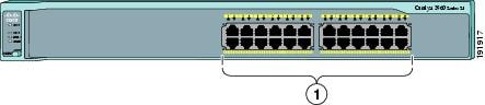
The 10/100 ports on the Catalyst 2960-24-S switch are numbered as follows: The first member of the pair (port 1) is above the second member (port 2), port 3 is above port 4, and so on. See Figure 1-1.
Figure 1-1 Catalyst 2960-24-S Switch Front Panel
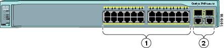
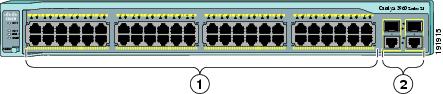
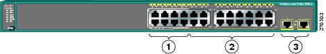
The 10/100 ports on the Catalyst 2960-24TC-S and Catalyst 2960-48TC-S switches are numbered in the same way as the Catalyst 2960-24T-S switch. These switches have dual-purpose ports, that is, 10/100/1000 ports 1 and 2 can use either the SFP module or the RJ-45 connector for that port, but not both at the same time. Use the software to set the connector type for these ports. For more information about the dual-purpose port, see the "Dual-Purpose Port" section. See Figure 1-2 and Figure 1-3.
Figure 1-2 Catalyst 2960-24TC-S Switch Front Panel
Figure 1-3 Catalyst 2960-48TC-S Switch Front Panel
Catalyst 2960-24PC-L 2960-24TC-L, 2960-48TC-L, 2960 -24LT-L, 2960-24TT-L, and 2960-48TT-L Switches
The 10/100 ports on the Catalyst 2960-24PC-L, 2960-24TC-L, 2960-48TC-L, 2960-24LT-L, 2960-24TT-L, and 2960-48TT-L switches are grouped in pairs. The first member of the pair (port 1) is above the second member (port 2), port 3 is above port 4, and so on.
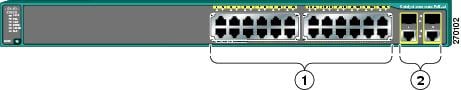
The 24 Catalyst 2960-24PC-L switch 10/100 ports are PoE ports. See Figure 1-4.
Figure 1-4 Catalyst 2960-24PC-L Switch Front Panel
The Catalyst 2960-24TC-L and Catalyst 2960-48TC-L switches have dual-purpose ports, that is, 10/100/1000 ports 1 and 2 can use either the SFP module or the RJ-45 connector for that port, but not both. Use the software to set the connector type for these ports. For more information about the dual-purpose port, see the "Dual-Purpose Port" section. See Figure 1-5 and Figure 1-6.
Figure 1-5 Catalyst 2960-24TC-L Switch Front Panel
Figure 1-6 Catalyst 2960-48TC-L Switch Front Panel
The Catalyst 2960-24LT-L, Catalyst 2960-24TT-L, and Catalyst 2960-48TT-L switches have two 10/100/1000 uplink ports, numbered 1 and 2. Ports 1 to 8 on the Catalyst 2960-24LT-L switch are PoE ports. See Figure 1-7, Figure 1-8, and Figure 1-9.
Figure 1-7 Catalyst 2960-24LT-L Switch Front Panel
Figure 1-8 Catalyst 2960-24TT-L Switch Front Panel
Figure 1-9 Catalyst 2960-48TT-L Switch Front Panel
Catalyst 2960G-24TC-L and Catalyst 2960G-48TC-L Switches
The 10/100/1000 ports on the Catalyst 2960G-24TC-L and Catalyst 2960G-48TC-L switches are grouped in pairs. The first member of the pair (port 1) is above the second member (port 2), port 3 is above port 4, and so on. The SFP module slots are numbered 21 to 24 on the Catalyst 2960G-24TC-L switch and 45 to 48 on the Catalyst 2960G-48TC-L switch. See Figure 1-10 and Figure 1-11.
The Catalyst 2960G-24TC-L and Catalyst 2960G-48TC-L switches have dual-purpose ports, meaning ports 21 to 24 or 45 to 48 can use either the SFP module or the RJ-45 connector for that port, but not both. Use the software to set the connector type for these ports. For more information about the dual-purpose port, see the "Dual-Purpose Port" section.
Figure 1-10 Catalyst 2960G-24TC-L Switch Front Panel
Figure 1-11 Catalyst 2960G-48TC-L Switch Front Panel
Catalyst 2960 Switch 8-Port Switches
These sections describe the Catalyst 2960 8-port switches:
•
Catalyst 2960PD-8TT-L Switch
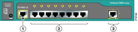
The Catalyst 2960PD-8TT-L (Figure 1-12) switch front panel has a console port, eight 10/100 ports, and a 10/100/1000 uplink port that can receive power from an upstream PoE switch. The switch can also receive power from an AC power adapter that is connected through the rear panel.
Figure 1-12 Catalyst 2960PD-8TT-L Switch Front Panel
Catalyst 2960-8TC-L Catalyst 2960G-8TC -L Switches
The console ports for the Catalyst 2960-8TC-L and Catalyst 2960G-8TC-L switches (Figure 1-13 and Figure 1-14) are on the front panels. The switches also have a dual-purpose port that can use either an RJ-45 connector or an SFP module, but not both. Use the software to set the connector type for these ports.
For more information on the dual-purpose port, see the "Dual-Purpose Port" section. For more information on the console port, see the "Console Port" section.
Figure 1-13 Catalyst 2960-8TC-L Switch Front Panel
Figure 1-14 Catalyst 2960G-8TC-L Switch Front Panel
10/100 Ports
You can set the 10/100 ports to operate at 10 or 100 Mb/s in full-duplex or half-duplex mode. You can also set these ports for speed and duplex autonegotiation. The default setting is autonegotiate. When the port is set to autonegotiate, it senses the speed and duplex settings of the attached device and advertises its own capabilities. If the connected device also supports autonegotiation, the switch port negotiates the best connection (that is, the fastest line speed that both devices support and full-duplex transmission if the attached device supports it) and configures itself accordingly. In all cases, the attached device must be within 328 feet (100 meters).
100BASE-TX traffic requires a Category 5 or higher cable. 10BASE-T traffic can use Category 3 or Category 4 cables.
When you connect the switch to workstations, servers, routers, and Cisco IP Phones, be sure that the cable is a straight-through cable. When you connect the switch to switches or hubs, use a crossover cable. Pinouts for the cables are described in Appendix A, "Connector and Cable Specifications."
You can use the mdix auto interface configuration command in the command-line interface (CLI) to enable the auto-MDIX feature. When the auto-MDIX feature is enabled, the switch detects the required cable type for copper Ethernet connections and configures the interfaces accordingly. Therefore, you can use either a crossover or a straight-through cable for connections to a copper 10/100/1000 or 1000BASE-T SFP module port on the switch, regardless of the type of device on the other end of the connection. For configuration information for this feature, see the switch software configuration guide or the switch command reference.
10/100/1000 Ports
You can set the 10/100/1000 ports to operate at 10, 100, or 1000 Mb/s in full-duplex or half-duplex mode. You can also set these ports for speed and duplex autonegotiation. (The default setting is autonegotiate.) When you set the port for autonegotiation, it senses the speed and duplex settings of the attached device and advertises its own capabilities. If the connected device also supports autonegotiation, the switch port negotiates the best connection (that is, the fastest line speed that both devices support and full-duplex transmission if the attached device supports it) and configures itself accordingly. In all cases, the attached device must be within 328 feet (100 meters).
100BASE-TX and 1000BASE-T traffic requires a Category 5 or higher cable. 10BASE-T traffic can use Category 3 or Category 4 cables.
When you connect the switch to workstations, servers, routers, and Cisco IP Phones, be sure that the cable is a straight-through cable. When you connect the switch to switches or hubs, use a crossover cable. When using a straight-through or crossover cable for 1000BASE-T connections, be sure to use a twisted four-pair, Category 5 or higher cable for proper operation. Pinouts for the cables are described in Appendix A, "Connector and Cable Specifications."
You can use the mdix auto interface configuration command in the CLI to enable the automatic medium-dependent interface crossover (auto-MDIX) feature. When the auto-MDIX feature is enabled, the switch detects the required cable type for copper Ethernet connections and configures the interfaces accordingly. Therefore, you can use either a crossover or a straight-through cable for connections to a copper 10/100/1000 or 1000BASE-T SFP module port on the switch, regardless of the type of device on the other end of the connection. For configuration information for this feature, see the switch software configuration guide or the switch command reference.
PoE Ports
This section applies only to the Catalyst 2960-24PC-L and Catalyst 2960 24LT-L switches.
Warning
The 10/100 ports on the Catalyst 2960-24PC-L and ports 1 to 8 of the 10/100 ports on the Catalyst 2960-24LT-L switches provide PoE support for devices that are compliant with IEEE 802.3af. The Cisco prestandard PoE is also supported for Cisco IP Phones and Cisco Aironet Access Points.
Each of the Catalyst 2960-24PC-L switch 10/100 ports and ports 1 to 8 on the Catalyst 2960-24LT-L switch deliver 15.4 W of PoE.
On a per-port basis, you can control whether Catalyst 2960 PoE port automatically provides power when you connect an IP phone or an access point. The device manager, Network Assistant, and the CLI provide two PoE settings for each 10/100 PoE port: Auto and Never.
When you select the Auto setting, the port provides power only if a valid powered device, such as an IEEE 802.3af-compliant powered device, a Cisco pre-standard IP phone, or a Cisco pre-standard Cisco access point, is connected to it. The Auto setting is the default. However, when you select the Never setting, the port does not provide power even if a Cisco IP phone or an access point is connected to it.
Cisco enhanced power negotiation allows some powered devices, such as the Cisco 7970G IP Phone, to operate in high-power mode on Catalyst 2960 PoE switches. The powered device and the switch negotiate through power-negotiation Cisco Discovery Protocol (CDP) messages for an agreed-upon power-consumption level. The negotiation allows a high-power Cisco powered device that consumes more than 7 W to operate at its highest power mode. The powered device first boots up in low-power mode, consumes less than 7 W, and negotiates to obtain enough power to operate in high-power mode. The device changes to high-power mode only when it receives confirmation from the switch. High-power devices can operate in low-power mode on switches that do not support power-negotiation CDP.
For information about configuring and monitoring PoE ports, see the switch software configuration guide.
You also can connect a Cisco IP Phone or Cisco Aironet Access Point to a Catalyst 2960 PoE switch 10/100 port and to an AC power source for redundant power. The powered device might switch to the AC power source as its primary power source upon being connected to it. In that case, the PoE port becomes the backup power source for the powered device.
If the primary source fails, the second power source becomes the primary power source to the powered device. During the power transfer, an IP phone might reboot or reestablish link with the switch.
For information about Cisco IP Phones and Cisco Aironet Access Points, see the documentation that came with your IP phone or access point.
Many legacy powered devices, including older Cisco IP phones and access points that do not fully support IEEE 802.3af, might not support PoE when connected to the switches by a crossover cable.
SFP Module Slots
The Catalyst 2960 switches (other than those listed) use Gigabit Ethernet SFP modules for Gigabit uplink connections and 100-Megabit SFP modules for 100-Megabit connections to establish fiber-optic connections. These Catalyst 2960 switches do not have an SFP module slot:
•
•
•
•
•
The transceiver modules are field-replaceable, providing the uplink interfaces when you insert an SFP module. You can use the SFP modules for Gigabit uplink connections to other switches. You use fiber-optic cables with LC connectors to connect to a fiber-optic SFP module. You use Category 5 or higher cable with RJ-45 connectors to connect to a copper SFP module.
For more information about these SFP modules, see your SFP module documentation or the release notes for your switch software. For more information about cabling requirements, see Appendix A, "Connector and Cable Specifications."
Dual-Purpose Port
You can configure a dual-purpose port as either a 10/100/1000 port or as an SFP module port.
Only one port can be active at a time. If both ports are connected, the SFP module port has priority. You cannot configure the priority setting.
You can set the 10/100/1000 ports to autonegotiate. You can also configure them as fixed 10, 100, or 1000 Mb/s (Gigabit) Ethernet ports. You can configure the duplex setting. See the software configuration for more information.
Power Input Port (Catalyst 2960PD-8TT-L Switch)
The Catalyst 2960PD-8TT-L can receive power from these sources:
1.
2.
Figure 1-15 Connecting Through a 10/100/1000 Port
Figure 1-16 Connecting Through an External AC Power Adapter
LEDs
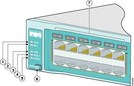
You can use the switch LEDs to monitor switch activity and its performance. Figure 1-17 shows and example of the switch LEDs and the Mode button that you use to select one of the port modes.
All LEDs are visible through the GUI management applications—Network Assistant for multiple switches and the device manager for a single switch. The switch software configuration guide describes how to use the CLI to configure and to monitor individual switches and switch clusters.
The Catalyst 2960-24PC-L and Catalyst 2960-24LT-L switches have a PoE LED.
The Catalyst 2960-8TC-L, 2960G-8TC-L, 2960PD-8TT-L, 2960-24-S, 2960-24TC-S, and 2960-48TC-S switches do not have an RPS LED.
Figure 1-17 Catalyst 2960 Switch LEDs
System LED
The System LED shows whether the system is receiving power and is functioning properly. Table 1-2 lists the LED colors and their meanings.
Table 1-2 System LED
Off
System is not powered on.
Green
System is operating normally.
Amber
System is receiving power but is not functioning properly.
RPS LED
The RPS LED shows the RPS status. Table 1-3 lists the LED colors and their meanings.
Note
For more information about the Cisco RPS 2300 or the Cisco RPS 675, see the related hardware installation guide for that power system.
Port LEDs and Modes
Each RJ-45 port and SFP module slot has a port LED. These port LEDs, as a group or individually, display information about the switch and about the individual ports. The port modes determine the type of information displayed through the port LEDs. Table 1-4 lists the mode LEDs and their associated port mode and meaning.
To select or change a mode, press the Mode button until the desired mode is highlighted. When you change port modes, the meanings of the port LED colors also change. Table 1-5 explains how to interpret the port LED colors in different port modes.
Even if PoE mode is not selected, the PoE LED still shows PoE problems when they are detected.
Table 1-6 lists the PoE mode LED colors and their meanings. The PoE LED applies only to Catalyst 2960 switches that support PoE.
To select or change a mode, press the Mode button until the desired mode is highlighted. When you change port modes, the meanings of the port LED colors also change. Table 1-7 explains how to interpret the port LED colors in different port modes.
Dual-Purpose Port LEDs
The LEDs on a dual-purpose port show whether an RJ-45 connector is connected to the port, or if an SFP module is installed in the slot. See the example in Figure 1-18. You can configure each port as either a 10/100/1000 port through the RJ-45 connector or as an SFP module, but not both at the same time. The LEDs show how the port is being used (Ethernet or SFP module).
The LED colors have the same meanings as described in Table 1-4 and Table 1-5.
Figure 1-18 Dual-Purpose Port LEDs
Cable Guard for the Catalyst 2960-8TC-L, 2960G-8TC-L, and 2960PD-8TT-L Switches
You can order an optional cable guard to secure cables to the front of the Catalyst 2960-8TC-L, 2960G-8TC-L, and 2960PD-8TT-L switches and to prevent them from being accidentally removed.
To order a cable guard, contact your Cisco representative using these part numbers:
•
•
Rear Panel Description
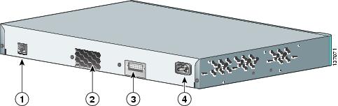
The rear panels on the Catalyst 2960 switches have all or some of these features: an RJ-45 console port, a fan exhaust, an RPS connector, and an AC power connector (see Figure 1-19.) These are the exceptions:
•
•
•
Figure 1-19 Catalyst 2960 Switch Rear Panel
Power Supplies
All switches other than the Catalyst 2960PD-8TT-L are powered through their internal power supply (see "Power Input Port (Catalyst 2960PD-8TT-L Switch)" section).
These sections describe the power connection options:
•
Internal Power Supply Connector
The internal power supply is an autoranging unit that supports input voltages between 100 and 240 VAC. Use the supplied AC power cord to connect the AC power connector to an AC power outlet.
Cisco RPS Connectors
You can connect the Cisco RPS 2300 or the Cisco RPS 675 to provide backup power if the switch internal power supply fails on those switches that have an RPS power connector.
Note
Connect the switch and the Cisco RPS 2300 or the Cisco RPS 675 to the same AC power source. See the Cisco redundant power systems (RPS) compatibility matrix documents on Cisco.com for more information about which RPS are supported on each of the Catalyst 2960 switches.
Use the supplied RPS connector cable to connect the RPS to the switch. For information about power requirements for the remote power system that you are connecting, see the hardware installation guide for that power system.
Warning
PWR-RPS2300, PWR675-AC-RPS-N1=. Statement 370
For more information about the Cisco RPS 675, see the Cisco RPS 675 Redundant Power System Hardware Installation Guide on Cisco.com.
Cisco RPS 2300 Connector
The Catalyst 2960-24PC-L and 2960-24LT-L switches support only the Cisco RPS 2300. This is a redundant power system that can support six network switches and provide power to one or two failed switches at a time. It automatically senses when the power supply of a connected switch fails and provides power to the failed switch, preventing loss of network traffic.
The Cisco RPS 2300 has two output levels: -52 V and 12 V. The total maximum output power depends on the installed power-supply modules.
The six ports on the RPS 2300 provide the power and management communication signals to the Catalyst 2960 switches. The RPS 2300 communicates with the Catalyst 2960-24PC-L and Catalyst 2960-24LT-L switches through the 22-pin cable (CAB-RPS2300-E=). All other Catalyst 2960 switches connect to the RPS 2300 through a 14-pin connector cable (CAB-RPS2300=).
All connected switches can simultaneously communicate with the RPS 2300. You can configure these RPS 2300 features through the switch software:
•
•
•
•
•
•
For more information about the RPS 2300, see the Cisco Redundant Power System 2300 Hardware Installation Guide on Cisco.com at this location:
http://www.cisco.com/en/US/products/ps7148/products_installation_guide_book09186a008075e608.html
Also see the switch software configuration guide on Cisco.com.
Console Port
You can connect the switch to a PC by means of the console port and the supplied RJ-45-to-DB-9 female cable. If you want to connect the switch console port to a terminal, you need to provide an RJ-45-to-DB-25 female DTE adapter. You can order a kit (part number ACS-DSBUASYN=) containing that adapter from Cisco. For console port and adapter pinout information, see the "Connector and Cable Specifications" section on page A-1.
Security Slots
The Catalyst 2960-8TC-L, 2960G-8TC-L, and 2960PD-8TT-L switches have security slots on the left and right side panels. You can install an optional cable lock, such as the type that is used to secure a laptop computer, to secure either or both sides of the switch.
Figure 1-20 shows the slot on a left-side panel.
Figure 1-20 Switch Left Panel
Management Options
The Catalyst 2960 switches offer several management options:
•
Network Assistant is a PC-based network management GUI application optimized for LANs of small and medium-sized businesses. Network Assistant offers centralized management of Cisco switches ranging from the Catalyst 2950 switch to the Catalyst 4506 switch. Through the GUI, you can configure and manage switch clusters or standalone switches.
Network Assistant is available at no cost and can be downloaded from this URL:
http://www.cisco.com/go/networkassistant
For information on starting Network Assistant, see the Getting Started with Cisco Network Assistant guide on Cisco.com.
•
You can use the device manager, which is in the switch memory, to manage individual and standalone switches. Device manager is a web interface that offers quick configuration and monitoring. You can access the device manager from anywhere in your network through a web browser. For more information, see the device manager online help.
•
The switch CLI is based on Cisco IOS software and is enhanced to support desktop-switching features. You can fully configure and monitor the switch and switch cluster members from the CLI. You can access the CLI either by connecting your management station directly to the switch console port or by using Telnet from a remote management station. See the Catalyst 2960 Switch Command Reference on Cisco.com for more information.
For setup instructions that use the CLI, go to Appendix C, "Configuring the Switch with the CLI-Based Setup Program."
•
The CiscoView device-management application displays the switch image that you can use to set configuration parameters and to view switch status and performance information. The CiscoView application, which you purchase separately, can be a standalone application or part of a Simple Network Management Protocol (SNMP) platform. See the CiscoView documentation for more information.
•
You can use SNMP management applications such as CiscoWorks LAN Management Solution (LMS) and HP OpenView to configure and manage the switch. You also can manage it from an SNMP-compatible workstation that is running platforms such as HP OpenView or SunNet Manager.
The Cisco Configuration Engine is a network management device that works with embedded CNS agents in the switch software. You can use Cisco Configuration Engine to automate initial configurations and configuration updates on the switch.
Network Configurations
See the switch software configuration guide on Cisco.com for an explanation of network configuration concepts. The software configuration guide also provides examples of network configurations that use the switch to create dedicated network segments that are interconnected through Gigabit Ethernet connections.