Table Of Contents
Switch Installation (8-Port Switches)
Statement 371—Power Cable and AC Adapter
Desk- or Shelf-Mounting (without Mounting Screws)
Desk- or Shelf-Mounting (with Mounting Screws)
Under the Desk- or Shelf-Mounting (with Mounting Screws)
Wall-Mounting (with Mounting Screws)
Attaching Brackets to the Switch
Mounting the Switch in a 19-Inch Rack
Wall-Mounting (with Rack-Mount Brackets)
Switch Installation (8-Port Switches)
This chapter describes how to start your switch and how to interpret the power-on self-test (POST) that ensures proper operation. It also describes how to install the switch. The installation information in this chapter is specific to the Catalyst 2960-8TC-L, Catalyst 2960G-8TC-L, and Catalyst 2960PD-8TT-L switches. For installation information applicable to the other Catalyst 2960 switches, see Chapter 2, "Switch Installation (24- and 48-Port Switches)."
Read the topics and perform the procedures in this order:
For information about connecting to the switch, see Chapter 2, "Switch Installation (24- and 48-Port Switches)."
Preparing for Installation
This section covers these topics:
Warnings
These warnings are translated into several languages in the Regulatory Compliance and Safety Information for the Catalyst 2960 Switch document that shipped with the switch.
Warning
To prevent the switch from overheating, do not operate it in an area that exceeds the maximum recommended ambient temperature of 113°F (45°C). To prevent airflow restriction, allow at least 3 inches (7.6 cm) of clearance around the ventilation openings. Statement 17B
Warning
Warning
Warning
Note
Warning
Statement 371—Power Cable and AC Adapter
Warning
Warning
Warning
Warning
Warning
Warning
Warning
Warning
Warning
Warning
Installation Guidelines
This section is specific to the Catalyst 2960 8-port switches. For information applicable to the other Catalyst 2960 switches, see Chapter 2, "Switch Installation (24- and 48-Port Switches)."
When you determine where to place the switch, be sure to observe these requirements:
•
•
We strongly recommend that you allow at least 3 inches (7.6 cm) of clearance around the ventilation openings.
•
If the switch is installed in a closed environment or in a multirack assembly, the temperature around it might be greater than normal room temperature.
•
•
•
•
•
•
•
•
–
–
–
•
•
•
When you use shorter lengths of single-mode fiber-optic cable, you might need to insert an inline optical attenuator in the link to avoid overloading the receiver.
When the fiber-optic cable span is less than 15.43 miles (25 km), you should insert a 5-decibel (dB) or 10-dB inline optical attenuator between the fiber-optic cable plant and the receiving port on the 1000BASE-ZX SFP module at each end of the link.
Equipment That You Supply
This section is specific to the Catalyst 2960 8-port switches. For information applicable to the other Catalyst 2960 switches, see Chapter 2, "Switch Installation (24- and 48-Port Switches)."
You need this equipment to install the switch:
•
•
You can order an optional cable guard to secure cables to the front of the switch and prevent them from being accidentally removed. To order a cable guard, contact your Cisco representative and use these part numbers:
•
•
The cable guard is a different part than the cable guide, which you can use to manage a large number of cables in a rack on switches other than the Catalyst 2960-8TC-L and Catalyst 2960G-8TC-L switches.
The switch has security slots in the left and right side panels. You can install an optional cable lock, such as the type that is used to secure a laptop computer, to secure either or both sides of the switch. Cable locks are available from most computer accessory suppliers.
Installing the Catalyst 2960 8-port switches in a 19-inch rack requires an optional bracket kit that is not included with the switch. You can order a kit containing the 19-inch rack-mounting brackets and hardware from Cisco. The kit part number is RCKMNT-19-CMPCT=.
If you want to connect a terminal to the switch console port, you need to provide an RJ-45-to-DB-25 female DTE adapter. You can order a kit (part number ACS-DSBUASYN=) with that adapter from Cisco.
Verifying Package Contents
This section is specific to the Catalyst 2960 8-port switches. For information that applies to all other Catalyst 2960 switches, see Chapter 2, "Switch Installation (24- and 48-Port Switches)."
Note
The switch is shipped with these items:
•
•
•
•
•
–
–
–
–
Verifying Switch Operation
Before installing the switch in a rack, or on a desk, a shelf, or a wall, you should power on the switch and verify that it passes POST.
To power on the switch, connect one end of the AC power cord to the AC power connector on the switch, and connect the other end of the power cord to an AC power outlet.
You can power the Catalyst 2960PD-8TT-L switch through a 10/100/1000 uplink port, which can receive power from an upstream PoE switch. You can also connect the switch to an AC power adapter on the rear panel. See the "Power Input Port (Catalyst 2960PD-8TT-L Switch)" section on page 1-11 for more information.
As the switch powers on, it begins the POST, a series of tests that runs automatically to ensure that the switch functions properly. LEDs can blink during the test. POST lasts approximately 1 minute. When the switch begins POST, the System, Status, Duplex, and Speed LEDs turn green. The System LED blinks green, and the other LEDs remain solid green.
When the POST completes successfully, the System LED remains green. The other LEDs turn off and then reflect the switch operating status. If a switch fails POST, the System LED turns amber.
POST failures are usually fatal. Call Cisco technical support representative if your switch fails POST.
After a successful POST, disconnect the power cord from the switch. Install the switch in a rack, or on a desk, a shelf, or a wall, as described in the "Installing the Switch" section.
Installing the Switch
This section is specific to the Catalyst 2960 8-port switches. For information applicable to the other Catalyst 2960 switches, see Chapter 2, "Switch Installation (24- and 48-Port Switches)."
This section describes these installation procedures:
•
•
•
•
•
Desk- or Shelf-Mounting (without Mounting Screws)
This section is specific to the Catalyst 2960 8-port switches. For information applicable to the other Catalyst 2960 switches, see Chapter 2, "Switch Installation (24- and 48-Port Switches)."
The switch can be installed on top of a desk or shelf with or without mounting screws. If you do not want to use the mounting screws, follow these steps:
Step 1
Step 2
Note
Step 3
Note
Do not stack switches or place switches side-by-side unless they are separated on all sides by at least 3 inches (7.6 cm) of clearance from each other.
Do not place any items on the top of the switch.After the switch is mounted on the desk or shelf, do these tasks to complete the installation:
1.
2.
3.
For configuration instructions about using the command-line interface (CLI) setup program, go to Appendix C, "Configuring the Switch with the CLI-Based Setup Program."
Desk- or Shelf-Mounting (with Mounting Screws)
This section is specific to the Catalyst 2960 8-port switches. For information applicable to the other Catalyst 2960 switches, see Chapter 2, "Switch Installation (24- and 48-Port Switches)."
The switch can be secured to a desk or shelf with mounting screws. Follow these steps:
Step 1
Step 2
Note
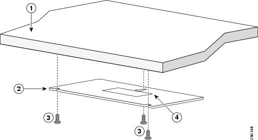
Figure 3-1 Installing the Mounting Screws on Top of a Desk or Shelf
Step 3
Step 4
Step 5
Step 6
Step 7
Note
Do not stack switches or place switches side-by-side unless they are separated on all sides with at least 3 inches (7.6 cm) of clearance from each other.
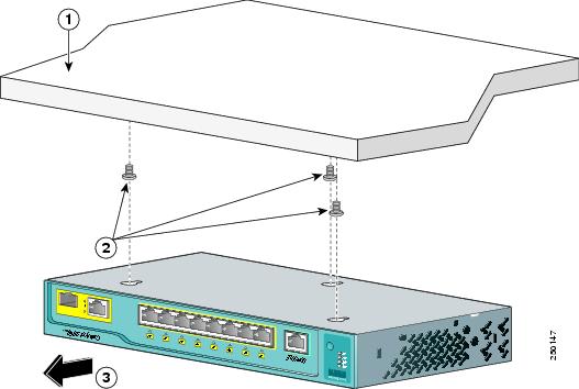
Do not place any items on the top of the switch.Figure 3-2 Mounting the Switch on Top of a Desk or Shelf
After the switch is mounted on the desk or shelf, do these tasks to complete the installation:
1.
2.
3.
For configuration instructions about using the CLI setup program, go to Appendix C, "Configuring the Switch with the CLI-Based Setup Program."
Under the Desk- or Shelf-Mounting (with Mounting Screws)
This section is specific to the Catalyst 2960 8-port switches. For information applicable to the other Catalyst 2960 switches, see Chapter 2, "Switch Installation (24- and 48-Port Switches)."
Follow these steps to install the switch under a desk or shelf:
Step 1
Step 2
Step 3
Figure 3-3 Installing the Mounting Screws Under a Desk or Shelf
Step 4
Step 5
Step 6
Step 7
Note
Figure 3-4 Mounting the Switch Under a Desk or Shelf
After the switch is mounted under the desk or shelf, do these tasks to complete the installation:
1.
2.
3.
For configuration instructions about using the CLI setup program, go to Appendix C, "Configuring the Switch with the CLI-Based Setup Program."
Wall-Mounting (with Mounting Screws)
This section is specific to the Catalyst 2960 8-port switches. For information applicable to the other Catalyst 2960 switches, see Chapter 2, "Switch Installation (24- and 48-Port Switches)."
The steps in this section show how to mount the switch with the front panel facing down (as shown in Figure 3-5 and Figure 3-6.)
Note
Follow the steps in this section to install the switch to a wall:
Step 1
Step 2
For the best support of the switch and cables, make sure that you attach the switch securely to a wall stud or to a firmly attached plywood mounting backboard.
Step 3
Figure 3-5 Installing the Mounting Screws on a Wall
Step 4
Step 5
Step 6
Step 7
Step 8
Figure 3-6 Installing the Switch On a Wall
After the switch is mounted on the wall, do these tasks to complete the installation:
1.
2.
3.
For configuration instructions about using the CLI setup program, go to Appendix C, "Configuring the Switch with the CLI-Based Setup Program."
Magnet Mounting
This section is specific to the Catalyst 2960 8-port switches. For information applicable to the other Catalyst 2960 switches, see Chapter 2, "Switch Installation (24- and 48-Port Switches)."
To mount a switch by using the magnet, follow these steps:
Step 1
Figure 3-7 Mounting the Switch with a Magnet
Step 2
After the switch is attached to the mounting magnet, do these tasks to complete the installation:
1.
2.
3.
For configuration instructions about using the CLI setup program, go to Appendix C, "Configuring the Switch with the CLI-Based Setup Program."
Rack-Mounting
This section is specific to the Catalyst 2960 8-port switches. For information applicable to the other Catalyst 2960 switches, see Chapter 2, "Switch Installation (24- and 48-Port Switches)."
Installing the Catalyst 2960 8-port switches in a 19-inch rack requires an optional bracket kit that is not included with the switch. You can order a kit containing the 19-inch rack-mounting brackets and hardware from Cisco. The kit part number is RCKMNT-19-CMPCT=.
To install the switch in a 19-inch rack, follow the instructions described in these sections:
•
•
Attaching Brackets to the Switch
Figure 3-8 shows how to attach a 19-inch bracket to one side of the switch. Follow the same steps to attach the second bracket to the opposite side.
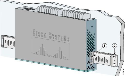
Figure 3-8 Attaching the 19-inch Brackets for Rack-Mounting
Mounting the Switch in a 19-Inch Rack
After the brackets are attached to the switch, insert the switch into the 19-inch rack, and align the bracket in the rack. Use either the 10-32 pan-head screws or the 12-24 pan-slotted screws to secure the switch in the rack, as shown in Figure 3-9.
Note
Figure 3-9 Mounting the Switch in a 19-Inch Rack
After the switch is mounted in the rack, do these tasks to complete the installation:
1.
2.
3.
For configuration instructions about using the CLI setup program, go to Appendix C, "Configuring the Switch with the CLI-Based Setup Program."
Wall-Mounting (with Rack-Mount Brackets)
To install the Catalyst 2960 8-port switches in a 19-inch rack requires an optional bracket kit that is not included with the switch. You can order a kit containing the 19-inch rack-mounting brackets and hardware from Cisco. The kit part number is RCKMNT-19-CMPCT=.
This section is specific to the Catalyst 2960 8-port switches. For information applicable to the other Catalyst 2960 switches, see Chapter 2, "Switch Installation (24- and 48-Port Switches)."
To mount the switch with brackets on a wall, follow these steps:
Step 1
Step 2
For the best support of the switch and cables, make sure the switch is attached securely to wall studs or to a firmly attached plywood mounting backboard.
Do not wall-mount the switch with its front panel facing up or sideways according to safety regulations. Wall-mount the switch with its front panel facing down to prevent airflow restriction and to provide easier access to the cables.
Figure 3-10 Mounting the Switch on a Wall
After the switch is mounted on the wall, do these tasks to complete the installation:
1.
2.
3.
For configuration instructions about using the CLI setup program, go to Appendix C, "Configuring the Switch with the CLI-Based Setup Program."
Where to Go Next
If the default configuration is satisfactory, the switch needs no further configuration. You can use any of these management options to change the default configuration:
•
•
•
•