Table Of Contents
Connector and Cable Specifications
Connecting to 10BASE-T- and 100BASE-TX-Compatible Devices
Connecting to 1000BASE-T Devices
Cable and Adapter Specifications
SFP Module Cable Specifications
Two Twisted-Pair Cable Pinouts
Four Twisted-Pair Cable Pinouts for 1000BASE-T Ports
Crossover Cable and Adapter Pinouts
Connector and Cable Specifications
This appendix describes the Catalyst 2960 switch ports and the cables and adapters that you use to connect the switch to other devices and includes these sections:
•
Cable and Adapter Specifications
Connector Specifications
These sections describe the connectors used with the Catalyst 2960 switch:
10/100/1000 Ports
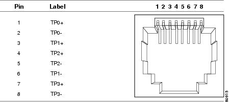
The 10/100/1000 Ethernet ports on the Catalyst 2960 switch use standard RJ-45 connectors. Figure A-1 shows the pinout.
Note
Connecting to 10BASE-T- and 100BASE-TX-Compatible Devices
When connecting the ports to 10BASE-T- and 100BASE-TX-compatible devices, such as servers, workstations, and routers, you can use a two or four twisted-pair, straight-through cable wired for 10BASE-T and 100BASE-TX. Figure A-5 shows the two twisted-pair, straight-through cable schematics. Figure A-7 shows the four twisted-pair, straight-through cable schematics.
When connecting the ports to 10BASE-T- and 100BASE-TX-compatible devices, such as switches or repeaters, you can use a two or four twisted-pair, crossover cable. Figure A-6 shows the two twisted-pair, crossover cable schematics. Figure A-8 shows the four twisted-pair, crossover cable schematics.
You can use Category 3, 4, or 5 cabling when connecting to 10BASE-T-compatible devices. You must use Category 5 cabling when connecting to 100BASE-TX-compatible devices.
Connecting to 1000BASE-T Devices
When connecting the ports to 1000BASE-T devices, such as servers, workstations, and routers, you must use a four twisted-pair, Category 5, straight-through cable wired for 10BASE-T, 100BASE-TX, and 1000BASE-T. Figure A-7 shows the straight-through cable schematics.
When connecting the ports to other devices, such as switches or repeaters, you must use a four twisted-pair, Category 5 or higher crossover cable. Figure A-8 shows the crossover cable schematics.
Note
Note
Figure A-1 10/100/1000 Port Pinouts
SFP Module Ports
The Catalyst 2960 switch uses SFP modules for fiber-optic and copper uplink ports. See the Catalyst 2960 switch release notes for a list of supported SFP modules.
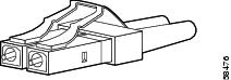
Figure A-2 Fiber-Optic SFP Module LC Connector
Warning
Figure A-3 Copper SFP Module RJ-45 Connector
Dual-Purpose Ports
The Ethernet port on a dual-purpose port uses standard RJ-45 connectors. Figure A-4 shows the pinouts.
The SFP module slot on a dual-purpose port uses SFP modules for fiber-optic and copper uplink ports. See the Catalyst 2960 switch release notes for a list of supported SFP modules.
Note
Figure A-4 10/100/1000 Port Pinouts
Console Port
The console port uses an 8-pin RJ-45 connector, which is described in Table A-2 and Table A-3. The supplied RJ-45-to-DB-9 adapter cable is used to connect the console port of the switch to a console PC. You need to provide a RJ-45-to-DB-25 female DTE adapter if you want to connect the switch console port to a terminal. You can order a kit (part number ACS-DSBUASYN=) containing that adapter from Cisco. For console port and adapter pinout information, see Table A-2 and Table A-3.
Cable and Adapter Specifications
These sections describe the cables and adapters used with Catalyst 2960 switches:
•
•
•
•
SFP Module Cable Specifications
Table A-1 lists the cable specifications for the fiber-optic SFP module connections. Each port must match the wave-length specifications on the other end of the cable, and for reliable communications, the cable must not exceed the required cable length. Copper 1000BASE-T SFP transceivers use standard four twisted-pair, Category 5 or greater cable at lengths up to 328 feet (100 meters).
Table A-1 Fiber-Optic SFP Module Port Cabling Specifications
100BASE-BX (GLC-FE-100BX-D
GLC-FE-100BX-U)1310 TX
1550 RXSMF
G.6522
—
32,810 feet (10 km)
100BASE-FX (GLC-GE-100FX)
1310
MMF
50/125
62.5/125500
5006,562 feet (2 km)
6,562 feet (2 km)100BASE-FX (GLC-FE-100FX)
1310
MMF
50/125
62.5/125500
5006,562 feet (2 km)
6,562 feet (2 km)100BASE-LX (100BASE-LX10)
1310
SMF
G.6522
—
32,810 feet (10 km)
1000BASE-BX10-D
(GLC-BX-D)1490 TX
1310 RXSMF
G.6522
—
32,810 feet (10 km)
1000BASE-BX10-U
(GLC-BX-U)1310 TX
1490 RXSMF
G.6522
—
32,810 feet (10 km)
1000BASE-SX
(GLC-SX-MM)850
MMF
62.5/125
62.5/125
50/125
50/125160
200
400
500722 feet (220 m)
902 feet (275 m)
1640 feet (500 m)
1804 feet (550 m)1000BASE-LX/LH
(GLC-LH-SM)1310
MMF3
SMF62.5/125
50/125
50/125
G.6522500
400
500
—1804 feet (550 m)
1804 feet (550 m)
1804 feet (550 m)
32,810 feet (10 km)1000BASE-ZX
(GLC-ZX-SM1550
SMF
G.6522
—
43.4 to 62 miles
(70 to 100 km)4CWDM
1470, 1490, 1510, 1530, 1550, 1570, 1590, 1610
SMF
G.6522
—
62 miles (100 km)
1 Modal bandwidth applies only to multimode fiber.
2 A mode-field diameter/cladding diameter = 9 micrometers/125 micrometers
3 A mode-conditioning patch cord is required. Using an ordinary patch cord with MMF, 1000BASE-LX/LH SFP modules, and a short link distance can cause transceiver saturation, resulting in an elevated bit error rate (BER). When using the LX/LH SFP module with 62.5-micron diameter MMF, you must also install a mode-conditioning patch cord between the SFP module and the MMF cable on both the sending and receiving ends of the link. The mode-conditioning patch cord is required for link distances greater than 984 feet (300 m).
4 1000BASE-ZX SFP modules can send data up to 62 miles (100 km) by using dispersion-shifted SMF or low-attenuation SMF; the distance depends on the fiber quality, the number of splices, and the connectors.
Two Twisted-Pair Cable Pinouts
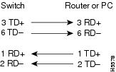
Figure A-5 and Figure A-6 show the schematics of two twisted-pair cables for connecting to 10BASE-T- and 100BASE-TX-compatible devices.
Figure A-5 Two Twisted-Pair Straight-Through Cable Schematic
Figure A-6 Two Twisted-Pair Crossover Cable Schematic
Four Twisted-Pair Cable Pinouts for 1000BASE-T Ports
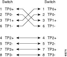
Figure A-7 and Figure A-8 show the schematics of four twisted-pair cables for 10/100/1000 ports on Catalyst 2960 switches.
Figure A-7 Four Twisted-Pair Straight-Through Cable Schematic for 10/100/1000 Ports
Figure A-8 Four Twisted-Pair Crossover Cable Schematics for 10/100/1000 Ports
Crossover Cable and Adapter Pinouts
This section describes how to identify a crossover cable and also describes the adapter pinouts.
Identifying a Crossover Cable
To identify a crossover cable, compare the two modular ends of the cable. Hold the cable ends side-by-side, with the tab at the back. The wire connected to the pin on the outside of the left plug should be a different color from the wire connected to the pin on the inside of the right plug. (See Figure A-9.)
Figure A-9 Identifying a Crossover Cable
Adapter Pinouts
Table A-2 lists the pinouts for the console port, the RJ-45-to-DB-9 adapter cable, and the console device.
Table A-3 lists the pinouts for the console port, RJ-45-to-DB-25 female DTE adapter, and the console device.
Note