-
Cisco MDS 9000 Family Switch-to-Switch Interoperability Configuration Guide
-
Index
-
Preface
-
Interoperability Overview
-
Interoperability Limitations
-
MDS 9000 Core with Brocade Edge Topology (Interop Mode 1)
-
MDS 9000 Core with Brocade and McData Edge Topology (Interop Mode 1)
-
MDS 9000 Switch and McData Dual Core Topology (Interop Mode 1)
-
MDS 9000 Core with Brocade 3900/12000 Edge Toplogy
-
MDS 9000 Legacy Switch Interop Mode 2
-
MDS 9000 Legacy Switch Interop Mode 3
-
MDS 9000 Legacy Switch Interop Mode 4
-
MDS 9020 Switch Interoperability
-
Interoperability with Inter-VSAN Routing
-
IBM BladeCenter
-
Standards Perspectives
-
Caveats
-
 Feedback
Table Of Contents
MDS 9000 Switch and McData Dual Core Topology (Interop Mode 1)
Configuring the McData 6064 Switch
Configuring the MDS 9000 Switch
Verifying the McData 6064 Switch
MDS 9000 Switch and McData Dual Core Topology (Interop Mode 1)
This chapter describes how to set up a basic dual-core topology with an MDS 9000 switch configured for interop mode 1 and a McData 6064 switch. Devices are connected to both core switches and all traffic must flow through both cores to reach its destination.
This chapter includes the following sections:
Specifications
The following switches and code levels were used for this example configuration:
•
MDS 9509 running SAN-OS Release 1.0(1)
•
Figure 5-1 shows the topology used for this example configuration.
Figure 5-1 MDS 9509 Switch and McData Switch Dual Core Topology
Note
Expected Topology Behavior
This section covers the Fibre Channel services and features that act differently in this topology (Figure 5-1) as compared to a homogeneous, single-vendor implementation.
It contains the following topics:
•
Zoning
In the core-core topology, zone members are all pWWNs, because the McData domain/port nomenclature is not a valid form according to the FC standard. When a zone set activation is made at one core switch, the zone set activation is sent to the other core switch. Either core switch may make zoning changes and have them be propagated to the other core switch.
Both core switches provide all of the zone security for the device attached ports because the MDS 9000 switch and the McData switches do not check the source and destination of the frame when traversing E ports. The MDS 9000 switch only provides hardware enforced security on the ingress ports to the fabric, while the McData switch only provides soft zoning.
Note
FSPF
All links within the topology show the link cost of 1000, because the McData 6064 switch used in this example only supports 1Gbps.
The McData switches load balance their routes using source/destination; the ingress edge switch uses the same ISL for all traffic that has the same source/destination pair. If the McData switch can load balance using source/destination/ox-id, then it can choose either of the ISLs for the route through the fabric. The MDS switch continues to load balance across ISLs using source/destination/ox-id of the frame.
Trunking and PortChannels
The lack of MDS 9000 switch-to-MDS 9000-switch connections prohibits the topology from containing TE ports or PortChannels. Only standard E ports are used for the ISLs.
Domain IDs
The domain IDs are limited to the 97 to 127 range due to a restriction imposed by McData's inability to handle IDs outside of that range. While the MDS 9000 switch can handle domain IDs outside of this range in its normal mode of operation, the implementation of interoperability mode includes this limitation.
Domain ID modifications can be handled in two ways, disruptively or nondisruptively:
•
•
Configuration
This section describes the configuration process and includes the following topics:
•
•
Configuring the McData 6064 Switch
In this example, the McData 6064 switch is configured for interop mode using Telnet and the CLI. The switch is placed in an offline state, the default zone is set to deny, the domain ID is set to 0x61 (97), and timers are altered to match the fabric.
Follow these steps to configure the McData 6064 switch.
Step 1
Root> show switchSwitch InformationState: OnlineBB Credit: 16R_A_TOV: 100 <==== must match other fabric switchesE_D_TOV: 20 <==== must match other fabric switchesPreferred Domain ID: 2Switch Priority: DefaultSpeed: 1 Gb/secRerouting Delay: DisabledOperating Mode: Open SystemsInterop Mode: Open Fabric 1.0 <==== non interop modeActive Domain ID: 2World Wide Name: 10:00:08:00:88:20:80:43Insistent Domain ID: DisabledDomain RSCN: DisabledStep 2
Root> config switchConfig.Switch>.. - Move back one levelbbCredit - Set the buffer to buffer credit value for the switchcommadelim - Toggle comma-delimited display modedomainRSCN - Set the Domain RSCN state for the switchedTOV - Set the E_D_TOV for the switchinsistDomainId - Set the Insistent Domain ID state for the switchinteropMode - Set the Interoperability mode for the switchlogin - Login to CLI under different access rightslogout - Logout of CLIprefDomainId - Set the preferred domain id for the switchpriority - Set the switch priorityraTOV - Set the R_A_TOV for the switchrerouteDelay - Enable or disable the reroute delayroot - Move back to root levelshow - Display the switch configurationspeed - Set the switch operating speedStep 3
Config.Switch> interopmode openError 45: Not Allowed While Switch Online
Note
Root> maintMaint> systemMaint.System> setOnlineState 0Maint.System> .Maint> .Root> show switchSwitch InformationState: Offline <==== switch is now offlineBB Credit: 16R_A_TOV: 100E_D_TOV: 20Preferred Domain ID: 1Switch Priority: DefaultSpeed: 1 Gb/secRerouting Delay: DisabledOperating Mode: Open SystemsInterop Mode: McDATA Fabric 1.0Active Domain ID: 1World Wide Name: 10:00:08:00:88:20:80:43Insistent Domain ID: DisabledDomain RSCN: DisabledStep 4
Root> config switchConfig.Switch> interopmode openError 81: Default Zone EnabledRoot> config zoningConfig.Zoning> setDefZoneState 0Config.Zoning> ..Config> switchConfig.Switch> interopmode openConfig.Switch> ..Config> ..Root> show switchSwitch InformationState: Offline <==== still offlineBB Credit: 16R_A_TOV: 100E_D_TOV: 20Preferred Domain ID: 1Switch Priority: DefaultSpeed: 1 Gb/secRerouting Delay: DisabledOperating Mode: Open SystemsInterop Mode: Open Fabric 1.0 <==== now in interop modeActive Domain ID: 1World Wide Name: 10:00:08:00:88:20:80:43Insistent Domain ID: DisabledDomain RSCN: DisabledStep 5
Root> config switchConfig.Switch> prefDomainId 1Config.Switch> ..Config> ..Root> maintMaint> systemMaint.System> setonlinestate 1Maint.System> ..Maint> ..Root> show switchSwitch InformationState: Online <==== onlineBB Credit: 16R_A_TOV: 100E_D_TOV: 20Preferred Domain ID: 1Switch Priority: DefaultSpeed: 1 Gb/secRerouting Delay: DisabledOperating Mode: Open SystemsInterop Mode: Open Fabric 1.0 <=== interop modeActive Domain ID: 0World Wide Name: 10:00:08:00:88:20:80:43Insistent Domain ID: DisabledDomain RSCN: Disabled
Configuring the MDS 9000 Switch
See "MDS 9000 Core with Brocade Edge Topology (Interop Mode 1)," for examples of how to set the MDS 9000 switch to interop mode.
Verification
This section highlights the commands used to verify that the fabric is up and running in interoperability mode. It includes the following topics:
•
•
Verifying the McData 6064 Switch
The following examples show the commands used to verify the configuration of the McData 6064 switch.
Root> show switchSwitch InformationState: OnlineBB Credit: 16R_A_TOV: 100E_D_TOV: 20Preferred Domain ID: 1Switch Priority: DefaultSpeed: 1 Gb/secRerouting Delay: DisabledOperating Mode: Open SystemsInterop Mode: Open Fabric 1.0Active Domain ID: 1World Wide Name: 10:00:08:00:88:20:80:43Insistent Domain ID: DisabledDomain RSCN: DisabledRoot> show systemSystem InformationName: 6064-01Description: FC Director Class SwitchContact:Location: LabDate/Time: 12/17/2002 12:50:18Serial Number: -Type Number: ED6064Model Number: 64EC Level: -Firmware Version: 04.01.00 12Beaconing: DisabledIssue the show port status command to verify that the correct ports are online, and are type E port or F port.
Root> show port statusPort State Type Attached WWN Beaconing---- ------------------ ----- ----------------------- ---------0 No Light gPort 00:00:00:00:00:00:00:00 Off1 No Light gPort 00:00:00:00:00:00:00:00 Off2 No Light gPort 00:00:00:00:00:00:00:00 Off3 Online fPort 21:00:00:E0:8B:07:A4:36 Off4 Not Installed gPort 00:00:00:00:00:00:00:00 Off5 Not Installed gPort 00:00:00:00:00:00:00:00 Off6 Not Installed gPort 00:00:00:00:00:00:00:00 Off7 Not Installed gPort 00:00:00:00:00:00:00:00 Off8 No Light gPort 00:00:00:00:00:00:00:00 Off9 No Light gPort 00:00:00:00:00:00:00:00 Off10 Online ePort 20:63:00:05:30:00:86:9F Off11 No Light gPort 00:00:00:00:00:00:00:00 Off12 Not Installed gPort 00:00:00:00:00:00:00:00 Off13 Not Installed gPort 00:00:00:00:00:00:00:00 Off14 Not Installed gPort 00:00:00:00:00:00:00:00 Off15 Not Installed gPort 00:00:00:00:00:00:00:00 Off16 Not Installed gPort 00:00:00:00:00:00:00:00 Off17 Not Installed gPort 00:00:00:00:00:00:00:00 Off18 Not Installed gPort 00:00:00:00:00:00:00:00 Off19 Not Installed gPort 00:00:00:00:00:00:00:00 Off20 Not Installed gPort 00:00:00:00:00:00:00:00 Off21 Not Installed gPort 00:00:00:00:00:00:00:00 Off22 Not Installed gPort 00:00:00:00:00:00:00:00 Off23 Not Installed gPort 00:00:00:00:00:00:00:00 Off24 Not Installed gPort 00:00:00:00:00:00:00:00 Off25 Not Installed gPort 00:00:00:00:00:00:00:00 Off26 Not Installed gPort 00:00:00:00:00:00:00:00 Off27 Not Installed gPort 00:00:00:00:00:00:00:00 Off28 Not Installed gPort 00:00:00:00:00:00:00:00 Off29 Not Installed gPort 00:00:00:00:00:00:00:00 Off30 Not Installed gPort 00:00:00:00:00:00:00:00 Off31 Not Installed gPort 00:00:00:00:00:00:00:00 Off32 Not Installed gPort 00:00:00:00:00:00:00:00 Off33 Not Installed gPort 00:00:00:00:00:00:00:00 Off34 Not Installed gPort 00:00:00:00:00:00:00:00 Off35 Not Installed gPort 00:00:00:00:00:00:00:00 Off36 Not Installed gPort 00:00:00:00:00:00:00:00 Off37 Not Installed gPort 00:00:00:00:00:00:00:00 Off38 Not Installed gPort 00:00:00:00:00:00:00:00 Off39 Not Installed gPort 00:00:00:00:00:00:00:00 Off40 Not Installed gPort 00:00:00:00:00:00:00:00 Off41 Not Installed gPort 00:00:00:00:00:00:00:00 Off42 Not Installed gPort 00:00:00:00:00:00:00:00 Off43 Not Installed gPort 00:00:00:00:00:00:00:00 Off44 Not Installed gPort 00:00:00:00:00:00:00:00 Off45 Not Installed gPort 00:00:00:00:00:00:00:00 Off46 Not Installed gPort 00:00:00:00:00:00:00:00 Off47 Not Installed gPort 00:00:00:00:00:00:00:00 Off48 Not Installed gPort 00:00:00:00:00:00:00:00 Off49 Not Installed gPort 00:00:00:00:00:00:00:00 Off50 Not Installed gPort 00:00:00:00:00:00:00:00 Off51 Not Installed gPort 00:00:00:00:00:00:00:00 Off52 Online ePort 20:63:00:05:30:00:86:9F Off53 No Light gPort 00:00:00:00:00:00:00:00 Off54 No Light gPort 00:00:00:00:00:00:00:00 Off55 No Light gPort 00:00:00:00:00:00:00:00 Off56 Not Installed gPort 00:00:00:00:00:00:00:00 Off57 Not Installed gPort 00:00:00:00:00:00:00:00 Off58 Not Installed gPort 00:00:00:00:00:00:00:00 Off59 Not Installed gPort 00:00:00:00:00:00:00:00 Off60 No Light gPort 00:00:00:00:00:00:00:00 Off61 No Light gPort 00:00:00:00:00:00:00:00 Off62 No Light gPort 00:00:00:00:00:00:00:00 Off63 No Light gPort 00:00:00:00:00:00:00:00 OffThe show nameserver command shows that the Netfinity host has logged into the McData switch.
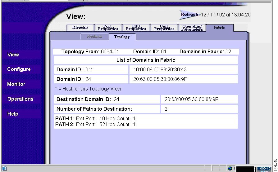
Root> show nameserverType Port Id Port Name Node Name COS FC4 Types---- ------- ----------------------- ----------------------- --- ------fPort 610713 20:00:00:E0:8B:07:A4:36 21:00:00:E0:8B:07:A4:36 3 N/A0. ISO/IEC 8802-2 LLC1. ISO/IEC 8802-2 LLC/SNAP2. SCSI-FCP3. SCSI-GPP4. IPI-3 Master5. IPI-3 Slave6. IPI-3 Peer7. CP IPI-3 Master8. CP IPI-3 Slave9. CP IPI-3 Peer10. SBCCS-Channel11. SBCCS-Cntrl Unit12. FC Srvcs13. FC-FG14. FC-XS15. FC-AL16. SNMP17. HIPPI-FP18. Vendor UniqueRoot> show loginserverPort BB Crdt RxFldSz COS Port Name Node Name---- ------- ------- --- ----------------------- -----------------------3 3 2048 3 20:00:00:E0:8B:07:A4:36 21:00:00:E0:8B:07:A4:36To view the FSPF routes used by the McData 3032 switch, use the Web GUI tool (Figure 5-2). There is no command line entry available to show this information.
Figure 5-2 McData Core Displaying Routes
Verifying the MDS 9509 Switch
The following examples show the commands used to verify the configuration of the MDS 9509 switch.
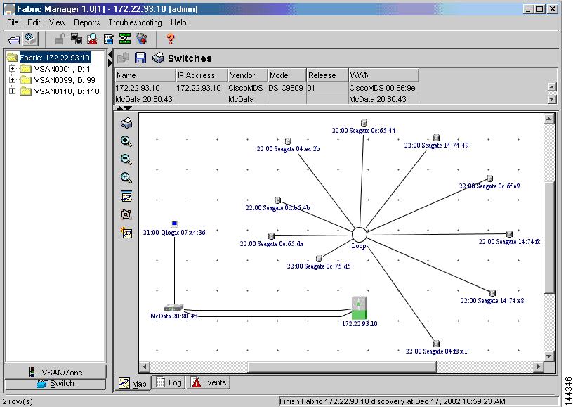
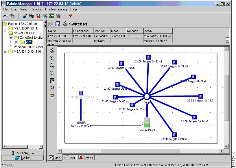
switch# show versionCisco Storage Area Networking Operating System (SAN-OS) SoftwareTAC support: http://www.cisco.com/tacCopyright (c) 2002 by Cisco Systems, Inc. All rights reserved.The copyright for certain works contained herein are owned byAndiamo Systems, Inc. and/or other third parties and are used anddistributed under license.SoftwareBIOS: version 1.0.2loader: version 1.0(1)kickstart: version 1.0(1)system: version 1.0(1)BIOS compile time: 10/18/02kickstart image file is: bootflash:/boot-1.0.1.binkickstart compile time: 12/4/2002 21:00:00system image file is: bootflash:/isan-1.0.1.binsystem compile time: 12/4/2002 21:00:00HardwareRAM 1027636 kBbootflash: 503808 blocks (block size 512b)slot0: 0 blocks (block size 512b)172.22.93.10 uptime is 0 days 2 hours 16 minute(s) 21 second(s)Last resetReason: Watchdog Timeout/External ResetSystem version: 1.0(1)switch# show int br-------------------------------------------------------------------------------Interface Vsan Admin Admin Status Oper Oper Port-channelMode Trunk Mode SpeedMode (Gbps)-------------------------------------------------------------------------------fc1/1 1 FX -- fcotAbsent -- -- --fc1/2 99 TL -- up TL 1 --fc1/3 1 FX -- fcotAbsent -- -- --fc1/4 1 FX -- fcotAbsent -- -- --fc1/5 1 FX -- fcotAbsent -- -- --fc1/6 1 FX -- fcotAbsent -- -- --fc1/7 1 FX -- fcotAbsent -- -- --fc1/8 1 FX -- fcotAbsent -- -- --fc1/9 1 FX -- fcotAbsent -- -- --fc1/10 1 FX -- fcotAbsent -- -- --fc1/11 1 FX -- fcotAbsent -- -- --fc1/12 1 FX -- fcotAbsent -- -- --fc1/13 1 FX -- fcotAbsent -- -- --fc1/14 1 FX -- fcotAbsent -- -- --fc1/15 1 FX -- fcotAbsent -- -- --fc1/16 1 FX -- fcotAbsent -- -- --fc1/17 1 FX -- fcotAbsent -- -- --fc1/18 1 FX -- fcotAbsent -- -- --fc1/19 1 FX -- fcotAbsent -- -- --fc1/20 1 FX -- fcotAbsent -- -- --fc1/21 1 FX -- fcotAbsent -- -- --fc1/22 1 FX -- fcotAbsent -- -- --fc1/23 1 FX -- fcotAbsent -- -- --fc1/24 1 FX -- fcotAbsent -- -- --fc1/25 1 FX -- fcotAbsent -- -- --fc1/26 1 FX -- fcotAbsent -- -- --fc1/27 1 FX -- fcotAbsent -- -- --fc1/28 1 FX -- fcotAbsent -- -- --fc1/29 99 E auto up E 1 --fc1/30 1 FX -- fcotAbsent -- -- --fc1/31 1 FX -- fcotAbsent -- -- --fc1/32 1 FX -- fcotAbsent -- -- --fc3/1 1 auto on fcotAbsent -- -- --fc3/2 1 auto on fcotAbsent -- -- --fc3/3 1 auto on fcotAbsent -- -- --fc3/4 1 auto on fcotAbsent -- -- --fc3/5 99 auto off up E 1 --fc3/6 1 auto on fcotAbsent -- -- --fc3/7 1 auto on fcotAbsent -- -- --fc3/8 1 auto on fcotAbsent -- -- --fc3/9 1 E on fcotAbsent -- -- --fc3/10 1 auto on fcotAbsent -- -- --fc3/11 1 auto on fcotAbsent -- -- --fc3/12 1 auto on fcotAbsent -- -- --fc3/13 1 E off notConnected -- -- --fc3/14 1 auto on fcotAbsent -- -- --fc3/15 1 auto on fcotAbsent -- -- --fc3/16 1 auto on fcotAbsent -- -- ---------------------------------------------------------------------------------Interface Status Speed(Gbps)-------------------------------------------------------------------------------sup-fc0 up 1-------------------------------------------------------------------------------Interface Status IP Address Speed MTU-------------------------------------------------------------------------------mgmt0 up 172.22.93.10/24 100 Mbps 1500switch# show vsan 99vsan 99 informationname:VSAN0099 state:activeinteroperability mode:yesloadbalancing:src-id/dst-id/oxidoperational state:upswitch# show fcdomain v 99The local switch is the Principal Switch.Local switch run time information:State: StableLocal switch WWN: 20:63:00:05:30:00:86:9fRunning fabric name: 20:63:00:05:30:00:86:9fRunning priority: 2Current domain ID: 0x78(120)Local switch configuration information:State: EnabledAuto-reconfiguration: DisabledContiguous-allocation: DisabledConfigured fabric name: 20:01:00:05:30:00:28:dfConfigured priority: 128Configured domain ID: 0x00(0) (preferred)Principal switch run time information:Running priority: 2Interface Role RCF-reject---------------- ------------- ------------fc1/29 Downstream Disabledfc3/5 Non-principal Disabled---------------- ------------- ------------switch# show fcdomain domain-list v 99Number of domains: 2Domain ID WWN--------- -----------------------0x78(120) 20:63:00:05:30:00:86:9f [Local] [Principal]0x61(97) 10:00:08:00:88:20:80:43--------- -----------------------switch# show fspf internal route vsan 99FSPF Unicast Routes---------------------------VSAN Number Dest Domain Route Cost Next hops-----------------------------------------------99 0x61(97) 1000 fc3/5fc1/29switch# show fcns database vsan 99VSAN 99:--------------------------------------------------------------------------FCID TYPE PWWN (VENDOR) FC4-TYPE:FEATURE--------------------------------------------------------------------------0x610713 N 21:00:00:e0:8b:07:a4:36 (QLogic)0x7800d5 NL 22:00:00:20:37:0e:65:da (Seagate) scsi-fcp:target0x7800d6 NL 22:00:00:20:37:14:74:e8 (Seagate) scsi-fcp:target0x7800d9 NL 22:00:00:20:37:04:f8:a1 (Seagate) scsi-fcp:target0x7800da NL 22:00:00:20:37:0c:6f:a9 (Seagate) scsi-fcp:target0x7800dc NL 22:00:00:20:37:0d:b6:4b (Seagate) scsi-fcp:target0x7800e0 NL 22:00:00:20:37:0e:65:44 (Seagate) scsi-fcp:target0x7800e1 NL 22:00:00:20:37:0c:75:d5 (Seagate) scsi-fcp:target0x7800e2 NL 22:00:00:20:37:04:ea:2b (Seagate) scsi-fcp:target0x7800e4 NL 22:00:00:20:37:14:74:49 (Seagate) scsi-fcp:target0x7800e8 NL 22:00:00:20:37:14:74:fc (Seagate) scsi-fcp:targetTotal number of entries = 11You can use Fabric Manager and Device Manager to verify the current state of the fabric.
Figure 5-3 shows the fabric topology from Fabric Manager.
Figure 5-3 MDS 9000 Switch and McData Dual Core Displayed in Fabric Manager
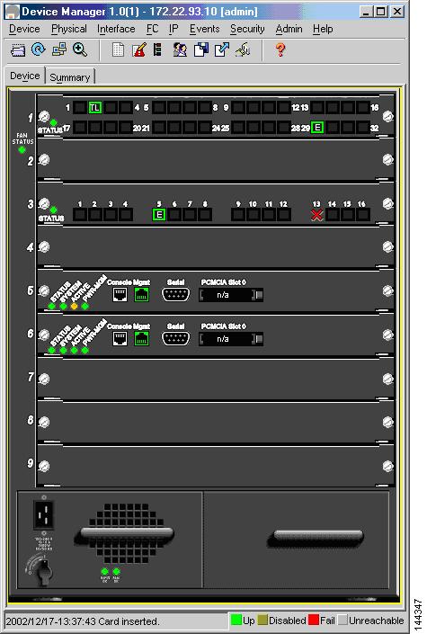
Figure 5-4 shows Device Manager on the MDS 9509 switch in the example topology. It shows which ports are active as E ports.
Figure 5-4 MDS 9509 Switch Device Manager Showing Active Ports
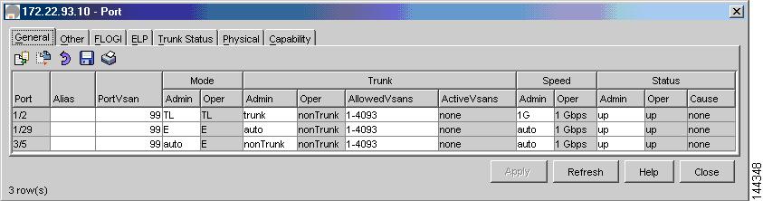
Figure 5-5 shows the status of the E ports and can verify link speed.
Figure 5-5 Fabric Manager Verifying Port Status and Type
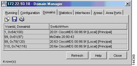
Figure 5-6 shows the domain ID of the switches in the fabric.
Figure 5-6 Fabric Manager Verifying Domains
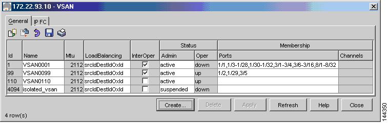
Figure 5-7 shows that VSAN 99 is operating in interop mode.
Figure 5-7 Verifying Interop Mode is Set
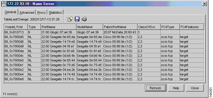
Figure 5-8 shows the MDS 9509 switch name server. This shows the edge devices that have registered.
Figure 5-8 MDS 9509 Switch Name Server Entries
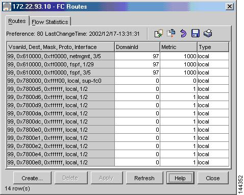
Figure 5-9 shows the FSPF routes as calculated by this switch.
Figure 5-9 FSPF Calculations in Fabric Manager
Zoning
In this example topology, Fabric Manager was used to create zones and zone sets. Fabric Manager displays are also used to verify the zone and zone set information.
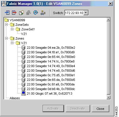
Figure 5-10 shows the zones and zone sets displayed in Fabric Manager.
Figure 5-10 Zoning Configuration for MDS 9000 Switch and McData Dual Core Topology
Figure 5-11 shows the zone VZ1.
Figure 5-11 Zone VZ1 Displayed in Fabric Manager
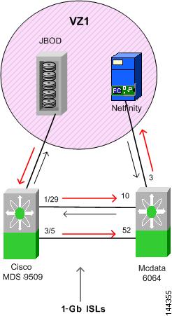
Figure 5-12 shows the FSPF traffic flow in this multi-vendor fabric.
Figure 5-12 MDS 9000 Switch and McData Dual Core FSPF Data Flow