-
Cisco MDS 9000 Family Switch-to-Switch Interoperability Configuration Guide
-
Index
-
Preface
-
Interoperability Overview
-
Interoperability Limitations
-
MDS 9000 Core with Brocade Edge Topology (Interop Mode 1)
-
MDS 9000 Core with Brocade and McData Edge Topology (Interop Mode 1)
-
MDS 9000 Switch and McData Dual Core Topology (Interop Mode 1)
-
MDS 9000 Core with Brocade 3900/12000 Edge Toplogy
-
MDS 9000 Legacy Switch Interop Mode 2
-
MDS 9000 Legacy Switch Interop Mode 3
-
MDS 9000 Legacy Switch Interop Mode 4
-
MDS 9020 Switch Interoperability
-
Interoperability with Inter-VSAN Routing
-
IBM BladeCenter
-
Standards Perspectives
-
Caveats
-
 Feedback
Table Of Contents
MDS 9000 Core with Brocade 3900/12000 Edge Topology
Configuring the MDS 9000 Switch
Configuring the Brocade 3900 Switch
Configuring the Brocade 12000 Switch
Verifying the Brocade 3900 Switch
Verifying the Brocade 12000 Switch
Creating Zones on the MDS 9000 Switch
Verifying Zoning on the Brocade 12000 Switch
Verifying Zoning on the Brocade 3900 Switch
MDS 9000 Core with Brocade 3900/12000 Edge Topology
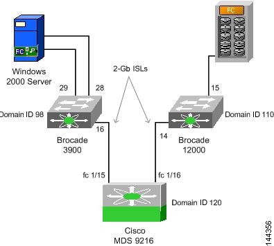
This chapter describes how to set up a basic core-edge topology with one MDS 9000 switch configured for interop mode 1 at the core and two Brocade switches at the edge. All devices are connected to the edge switches. However, all traffic must flow through the core switch to reach its destination.
This chapter includes the following sections:
Specifications
The following switches and code levels were used for this example configuration:
•
MDS 9216 running MDS SAN-OS Release 1.1(1)
•
•
Figure 6-1 shows the topology used for this example configuration.
Figure 6-1 MDS 9000 Switch Core Switch with Brocade 3900 and 12000 Edge Switch Topology
Expected Topology Behavior
This section covers the Fibre Channel services and features that act differently in this topology (Figure 6-1) as compared to a homogeneous, single-vendor implementation.
This section contains the following topics:
•
Zoning
In the core-edge topology (using standard interop mode), zone members are all pWWNs because the Brocade domain/port nomenclature is not a valid form according to the FC standard. When a zone set (or configuration, in Brocade terminology) activation is made at the core switch, the zone set activation reaches all switches at the same time because they are all the same distance from the core.
The Brocade edge switches provide all of the zone security because the MDS 9000 switch does not check the source and destination of the frame when traversing E ports. Brocade switches only check the zoning information on the egress port of the fabric.
Note
FSPF
All links within the topology show the link cost of 500.
Because the Brocade switches load balance their routes using source and destination, the ingress edge switch uses the same core switch for all traffic that has the same source and destination pair. If the Brocade switch could load balance using source/destination/ox-id, then it could choose either of the two core switches for the route through the fabric.
Trunking and PortChannels
The lack of MDS 9000 switch-to-MDS 9000-switch connections prohibits the topology from containing TE ports or PortChannels. While in interop mode, the Brocade switches do not support trunked ports of any type. Only standard E ports are used for the ISLs.
Domain IDs
The domain IDs are limited to the 97 to 127 range due to a restriction imposed by McData's inability to handle IDs outside of that range. While Brocade switches and MDS 9000 switches can handle domain IDs outside of this range, their implementation of interoperability mode includes this limitation.
Domain ID modifications can be handled in two ways, disruptively or nondisruptively:
•
•
Configuration
This section describes the configuration process and includes the following topics:
•
•
•
Configuring the MDS 9000 Switch
Follow these steps to configure the MDS 9000 switch.
Step 1
MDS9000# config tMDS9000(config)# vsan databaseMDS9000(config-vsan-db)# vsan 1 interopStep 2
In the MDS 9000 switch, the default is to request an ID from the principal switch. If the preferred keyword is used, the MDS 9000 switch requests a specific ID, but still joins the fabric if the principal switch assigns a different ID. If the static keyword is used, the MDS 9000 switch will not join the fabric unless the principal switch agrees, and assigns the requested ID.
MDS9000# config tMDS9000(config)# fcdomain domain 120 preferred vsan 1Step 3
MDS9000# config tMDS9000(config)# fctimer e_d_tov ?<1000-100000> E_D_TOV in milliseconds(1000-100000)MDS9000(config)# fctimer r_a_tov ?<5000-100000> R_A_TOV in milliseconds(5000-100000)Step 4
MDS9509(config)# vsan databaseMDS9509(config-vsan-db)# vsan 1 suspendMDS9509(config-vsan-db)# no vsan 1 suspend
Configuring the Brocade 3900 Switch
Follow these steps to configure the Brocade 3900 switch in interoperability mode.
Step 1
CA3900:admin> switchdisableStep 2
CA3900:admin> configureConfigure...Fabric parameters (yes, y, no, n): [no] yDomain: (97..239) [98] 98 <==== Assign domain id in the 97-127 rangeR_A_TOV: (4000..120000) [10000] <==== Must match other switches in the fabricE_D_TOV: (1000..5000) [2000] <==== Must match other switches in the fabricData field size: (256..2112) [2112]Sequence Level Switching: (0..1) [0]Disable Device Probing: (0..1) [0]Suppress Class F Traffic: (0..1) [0]VC Encoded Address Mode: (0..1) [0]Per-frame Route Priority: (0..1) [0]BB credit: (1..16) [16]Virtual Channel parameters (yes, y, no, n): [no]Zoning Operation parameters (yes, y, no, n): [no]RSCN Transmission Mode (yes, y, no, n): [no]NS Operation Parameters (yes, y, no, n): [no]Arbitrated Loop parameters (yes, y, no, n): [no]System services (yes, y, no, n): [no]Portlog events enable (yes, y, no, n): [no]Step 3
CA3900:admin> msPlMgmtDeactivateThis will erase all Platform entries. Are you sure? (yes, y, no, n): [no] yCommitting configuration...done.Request Fabric to Deactivate Platform Management services....Done.Step 4
CA3900:admin> interopmode 1 Set interop mode onCommitting configuration...done.interopMode is 1NOTE: It is recommended that you reboot the switch to make this change take effect
Note
CA3900:admin> fastbootTo return to non-interop mode, you must disable the switch. Reconfigure the switch, set the interoperability mode to 0, and then reboot.
Configuring the Brocade 12000 Switch
Follow these steps to configure the Brocade 12000 switch in interoperability mode.
Step 1
CA12000:admin> switchdisableStep 2
CA12000:admin> configureConfigure...Fabric parameters (yes, y, no, n): [no] yDomain: (97..239) [110] 110 <==== Assign domain id in the 97-127 rangeR_A_TOV: (4000..120000) [10000] <==== Must match other switches in the fabricE_D_TOV: (1000..5000) [2000] <==== Must match other switches in the fabricData field size: (256..2112) [2112]Sequence Level Switching: (0..1) [0]Disable Device Probing: (0..1) [0]Suppress Class F Traffic: (0..1) [0]VC Encoded Address Mode: (0..1) [0]Per-frame Route Priority: (0..1) [0]BB credit: (1..16) [16]Virtual Channel parameters (yes, y, no, n): [noZoning Operation parameters (yes, y, no, n): [nRSCN Transmission Mode (yes, y, no, n): [no]NS Operation Parameters (yes, y, no, n): [no]Arbitrated Loop parameters (yes, y, no, n): [noSystem services (yes, y, no, n): [no]Portlog events enable (yes, y, no, n): [no]Step 3
CA12000:admin> msPlMgmtDeactivateThis will erase all Platform entries. Are you sure? (yes, y, no, n): [no] yCommitting configuration...done.Request Fabric to Deactivate Platform Management services....Done.Step 4
CA12000:admin> interopmode 1 Set interop mode onCommitting configuration...done.interopMode is 1NOTE: It is recommended that you boot this switch to make this change take effect
Note
CA12000:admin> fastbootTo return to non-interop mode, disable the switch. Reconfigure the switch, set interoperability mode to 0, and then reboot.
Verification
The following section highlights the commands used to verify that the fabric is up and running in interoperability mode.
In this example topology, there are only single ISLs. If there were multiple ISLs connecting the edge Brocade switches to the core MDS 9000 switch, the Brocade switches would load balance their routes using source and destination, and the ingress edge switch would use the same ISL for all traffic that has the same source and destination pair. The MDS 9000 switch would continue to load balance across ISLs using the source/destination/ox-id of the frame. This principle is illustrated in Figure 5-12.
Verifying the MDS 9000 Switch
The following examples show verification of the MDS 9000 switch.
MDS9000# show versionCisco Storage Area Networking Operating System (SAN-OS) SoftwareTAC support: http://www.cisco.com/tacCopyright (c) 2002-2003 by Cisco Systems, Inc. All rights reserved.The copyright for certain works contained herein are owned byAndiamo Systems, Inc. and/or other third parties and are used anddistributed under license.SoftwareBIOS: version 1.0.7loader: version 1.0(3a) [last : 1.0(4)]kickstart: version 1.1(1)system: version 1.1(1)BIOS compile time: 03/20/03kickstart image file is: bootflash:/m9200-ek9-kickstart-mz.1.1.1.binkickstart compile time: 5/23/2003 0:00:00system image file is: bootflash:/m9200-ek9-mz.1.1.1.binsystem compile time: 5/23/2003 0:00:00HardwareRAM 963116 kBbootflash: 500736 blocks (block size 512b)slot0: 0 blocks (block size 512b)MDS9000 uptime is 1 days 21 hours 38 minute(s) 3 second(s)Last reset at 412363 usecs after Wed Jul 2 02:40:38 2003Reason: Reset Requested by management applicationSystem version: 1.1(1)MDS9000# show interface brief----------------------------------------------------------------------------Interface Vsan Admin Admin Status Oper Oper Port-channelMode Trunk Mode SpeedMode (Gbps)----------------------------------------------------------------------------fc1/1 1 auto on notConnected -- --fc1/2 1 auto on notConnected -- --fc1/3 1 auto on down -- --fc1/4 1 auto on down -- --fc1/5 1 auto on down -- --fc1/6 1 auto on down -- --fc1/7 1 auto on down -- --fc1/8 1 auto on down -- --fc1/9 1 auto on down -- --fc1/10 1 auto on down -- --fc1/11 1 auto on down -- --fc1/12 1 auto on down -- --fc1/13 1 auto on down -- --fc1/14 1 auto on down -- --fc1/15 1 auto on up E 2 --fc1/16 1 E on up E 2 ------------------------------------------------------------------------------Interface Status Speed(Gbps)----------------------------------------------------------------------------sup-fc0 up 1----------------------------------------------------------------------------Interface Status IP Address Speed MTU----------------------------------------------------------------------------mgmt0 up 172.22.36.255/23 100 Mbps 1500----------------------------------------------------------------------------Interface Status IP Address Speed MTU----------------------------------------------------------------------------vsan1 up -- 1 Gbps 1500MDS9000# show running-configBuilding Configuration ...vsan databasevsan 1 interopinterface vsan1snmp-server community public rwsnmp-server user admin network-admin auth md5 0xe649424ae4a77d12a40f7dd86f55965localizedkeysnmp-server host 10.10.3.20 traps version 1 publicsnmp-server host 171.69.122.33 traps version 2c public udp-port 2162snmp-server host 171.71.188.65 traps version 2c public udp-port 4058boot system bootflash:/m9200-ek9-mz.1.1.1.binboot kickstart bootflash:/m9200-ek9-kickstart-mz.1.1.1.binip default-gateway 172.22.36.1kernel core module 1 level ramkernel core module 2 level ramkernel core module 3 level ramkernel core module 4 level ramkernel core module 5 level ramkernel core module 6 level ramkernel core module 7 level ramkernel core module 8 level ramkernel core module 9 level ramkernel core module 10 level ramkernel core module 11 level ramkernel core module 12 level ramkernel core module 13 level ramkernel core module 14 level ramkernel core module 15 level ramswitchname MDS9000username admin password 5 AOpL5dCXKyzng role network-adminzone name Bro12000 vsan 1member pwwn 21:01:00:e0:8b:29:8b:3emember pwwn 21:00:00:e0:8b:09:8b:3emember pwwn 50:06:0e:80:03:4e:95:32zone default-zone permit vsan 2-4zoneset name BrocadeZoneSet vsan 1member Bro12000zoneset activate name BrocadeZoneSet vsan 1interface fc1/1no shutdowninterface fc1/2no shutdowninterface fc1/3interface fc1/4interface fc1/5interface fc1/6interface fc1/7interface fc1/8interface fc1/9interface fc1/10interface fc1/11interface fc1/12interface fc1/13interface fc1/14interface fc1/15no shutdowninterface fc1/16switchport mode Eno shutdowninterface mgmt0ip address 172.22.36.255 255.255.254.0MDS9000# show vsan 1vsan 1 informationname:VSAN0001 state:activeinteroperability mode:yesloadbalancing:src-id/dst-id/oxidoperational state:upMDS9000# show fcdomain vsan 1The local switch is a Subordinated Switch.Local switch run time information:State: StableLocal switch WWN: 20:01:00:05:30:00:68:5fRunning fabric name: 10:00:00:60:69:90:08:2fRunning priority: 128Current domain ID: 0x78(120) <==== Verify domain idLocal switch configuration information:State: EnabledFCID persistence: DisabledAuto-reconfiguration: DisabledContiguous-allocation: DisabledConfigured fabric name: 20:01:00:05:30:00:28:dfConfigured priority: 128Configured domain ID: 0x00(0) (preferred)Principal switch run time information:Running priority: 2Interface Role RCF-reject---------------- ------------- ------------fc1/15 Upstream Disabledfc1/16 Downstream Disabled---------------- ------------- ------------MDS9000# show fcdomain domain-list vsan 1Number of domains: 3Domain ID WWN--------- -----------------------0x62(98) 10:00:00:60:69:90:08:2f [Principal] <==== Brocade 39000x6e(110) 10:00:00:60:69:80:1d:cf <==== Brocade 120000x78(120) 20:01:00:05:30:00:68:5f [Local] <==== MDS9216MDS9000# show fspf internal route vsan 1FSPF Unicast Routes---------------------------VSAN Number Dest Domain Route Cost Next hops-----------------------------------------------1 0x62(98) 500 fc1/151 0x6e(110) 500 fc1/16MDS9000# show fspf internal route vsan 1FSPF Unicast Routes---------------------------VSAN Number Dest Domain Route Cost Next hops-----------------------------------------------1 0x62(98) 500 fc1/151 0x6e(110) 500 fc1/16MDS9000# show fcns database vsan 1VSAN 1:--------------------------------------------------------------------------FCID TYPE PWWN (VENDOR) FC4-TYPE:FEATURE--------------------------------------------------------------------------0x621c00 N 21:01:00:e0:8b:29:8b:3e (QLogic)0x621d00 N 21:00:00:e0:8b:09:8b:3e (QLogic)0x6e0e00 N 50:06:0e:80:03:4e:95:32 scsi-fcpTotal number of entries = 3
Note
Verifying the Brocade 3900 Switch
The following examples show verification of the Brocade 3900 switch.
CA3900:admin> versionKernel: 2.4.2Fabric OS: v4.0.2dMade on: Sat Apr 5 00:22:58 2003Flash: Mon Jun 23 18:49:49 2003BootProm: 3.1.18CA3900:admin> licenseshowedcczbyc9pedd0X:Web licenseZoning licenseFabric licenseFabric Watch licenseTrunking licenseCA3900:admin> switchshowswitchName: CA3900switchType: 12.1switchState: OnlineswitchRole: PrincipalswitchDomain: 98switchId: fffc62switchWwn: 10:00:00:60:69:90:08:2fswitchBeacon: OFFPort Gbic Speed State=========================0 -- N2 No_Module1 -- N2 No_Module2 -- N2 No_Module3 -- N2 No_Module4 -- N2 No_Module5 -- N2 No_Module6 -- N2 No_Module7 -- N2 No_Module8 -- N2 No_Module9 -- N2 No_Module10 -- N2 No_Module11 -- N2 No_Module12 -- N2 No_Module13 -- N2 No_Module14 -- N2 No_Module15 id N2 No_Light16 id N2 Online E-Port 20:01:00:05:30:00:68:5f (downstream)17 -- N2 No_Module18 -- N2 No_Module19 -- N2 No_Module20 -- N2 No_Module21 -- N2 No_Module22 -- N2 No_Module23 -- N2 No_Module24 -- N2 No_Module25 -- N2 No_Module26 -- N2 No_Module27 -- N2 No_Module28 id N2 Online F-Port 21:01:00:e0:8b:29:8b:3e29 id N2 Online F-Port 21:00:00:e0:8b:09:8b:3e30 id N2 No_Light31 id N2 No_LightCA3900:admin> topologyshow3 domains in the fabric; Local Domain ID: 98Domain: 110Metric: 1000Name: CA12000Path Count: 1Hops: 2Out Port: 16In Ports: 28 29Total Bandwidth: 2 GbpsBandwidth Demand: 200 %Flags: DDomain: 120Metric: 500Name: UnknownPath Count: 1Hops: 1Out Port: 16In Ports: 28 29Total Bandwidth: 2 GbpsBandwidth Demand: 200 %Flags: DCA3900:admin> interopmodeInteropMode: OnUsage: InteropMode 0|10: to turn it off1: to turn it onCA3900:admin> nsallshow3 Nx_Ports in the Fabric {621c00 621d00 6e0e00}
Note
CA3900:admin> urouteshowLocal Domain ID: 98In Port Domain Out Port Metric Hops Flags Next (Dom, Port)----------------------------------------------------------------------------28 110 16 1000 2 D 120,65550120 16 500 1 D 120,65550Verifying the Brocade 12000 Switch
The following examples show the commands used to verify the configuration of the Brocade 12000 switch.
CA12000:admin> versionKernel: 2.4.2Fabric OS: v4.0.2cMade on: Wed Jan 22 04:17:49 2003Flash: Thu Mar 20 23:48:04 2003BootProm: 3.1.18CA12000:admin> licenseshowSQeRRcyyRzdRfSSz:Web licenseZoning licenseFabric Watch licenseTrunking licenseRzb9SzQc99S0cATc:Fabric licenseCA12000:admin> switchshowswitchName: CA12000switchType: 10.1switchState: OnlineswitchRole: SubordinateswitchDomain: 110switchId: fffc6eswitchWwn: 10:00:00:60:69:80:1d:cfswitchBeacon: OFFblade7 Beacon: OFFArea Slot Port Gbic Speed State=====================================0 7 0 id N2 No_Light1 7 1 id N2 No_Light2 7 2 id N2 No_Light3 7 3 id N2 No_Light4 7 4 id N2 No_Light5 7 5 id N2 No_Light6 7 6 id N2 No_Light7 7 7 id N2 No_Light8 7 8 id N2 No_Light9 7 9 id N2 No_Light10 7 10 id N2 No_Light11 7 11 id N2 No_Light12 7 12 id N2 No_Light13 7 13 id N2 No_Light14 7 14 id N2 Online F-Port 50:06:0e:80:03:4e:95:3215 7 15 id N2 Online E-Port 20:01:00:05:30:00:68:5f (upstream)CA12000:admin> topologyshow3 domains in the fabric; Local Domain ID: 110Domain: 98Metric: 1000Name: CA3900Path Count: 1Hops: 2Out Port: 7/15In Ports: 7/14Total Bandwidth: 2 GbpsBandwidth Demand: 100 %Flags: DDomain: 120Metric: 500Name: UnknownPath Count: 1Hops: 1Out Port: 7/15In Ports: 7/14Total Bandwidth: 2 GbpsBandwidth Demand: 100 %Flags: DCA12000:admin> interopmodeInteropMode: OnUsage: InteropMode 0|10: to turn it off1: to turn it onCA12000:admin> nsshowThe Local Name Server has 1 entry {Type Pid COS PortName NodeName TTL(sec)N 6e0e00; 3;50:06:0e:80:03:4e:95:32;50:06:0e:80:03:4e:95:32; naFC4s: FCP [HITACHI OPEN-3 2105]Fabric Port Name: 20:0e:00:60:69:80:1d:cf}CA12000:admin> nsallshow3 Nx_Ports in the Fabric {621c00 621d00 6e0e00}
Note
CA12000:admin> urouteshowLocal Domain ID: 110In Port Domain Out Port Metric Hops Flags Next (Dom, Port)----------------------------------------------------------------------------14 98 15 1000 2 D 120,65551120 15 500 1 D 120,65551Zoning
In this example, the zone is created on the MDS 9000 switch and the zone set is activated. After activation, the verification process confirms that the Brocade switches properly learn the zones and zone sets. In Brocade terminology, the zone set is known as the configuration. On Brocade switches, the MDS 9000 active zone set is known as the effective configuration.
The example shows how to use the name server database as a tool when building the zones. When predefining zones, you may use pWWNs of equipment not attached, or in the name server database.
Zones that are defined while the switch is in interop mode must be zoned by pWWN. Zoning by alias or FC ID is not permitted while the Brocade switch is operating in interop mode. This limits the Brocade switches to soft zoning. The MDS 9000 switch will always implement hardware-enforced zoning.
Creating Zones on the MDS 9000 Switch
Follow these steps to create zones on the MDS 9000 switch.
Step 1
MDS9000# show fcns database vsan 1VSAN 1:--------------------------------------------------------------------------FCID TYPE PWWN (VENDOR) FC4-TYPE:FEATURE--------------------------------------------------------------------------0x621c00 N 21:01:00:e0:8b:29:8b:3e (QLogic)0x621d00 N 21:00:00:e0:8b:09:8b:3e (QLogic)0x6e0e00 N 50:06:0e:80:03:4e:95:32 scsi-fcpTotal number of entries = 3Step 2
MDS9000# conf tEnter configuration commands, one per line. End with CNTL/Z.MDS9000(config)# zone name Bro12000 vsan 1MDS9000(config-zone)# member pwwn 21:01:00:e0:8b:29:8b:3eMDS9000(config-zone)# member pwwn 21:00:00:e0:8b:09:8b:3eMDS9000(config-zone)# member pwwn 50:06:0e:80:03:4e:95:32MDS9000(config)#MDS9000(config)# zoneset name BrocadezoneSet vsan 1MDS9000(config-zoneset)# member Bro12000At this point, we have created one zone (Bro12000) within the zone set named BrocadeZoneSet.
Step 3
MDS9000(config)# zoneset activate name BrocadeZoneSet vsan 1Zoneset Activation initiated. check zone statusMDS9000(config)# exitStep 4
MDS9000# show zoneset active vsan 1zoneset name BrocadeZoneSet vsan 1zone name Bro12000 vsan 1* fcid 0x621c00 [pwwn 21:01:00:e0:8b:29:8b:3e]* fcid 0x621d00 [pwwn 21:00:00:e0:8b:09:8b:3e]* fcid 0x6e0e00 [pwwn 50:06:0e:80:03:4e:95:32]
Verifying Zoning on the Brocade 12000 Switch
The Brocade 12000 switch does not have a defined configuration, but it does contain an effective configuration. The effective configuration was passed to it by the MDS 9000 switch when the MDS 9000 switch full zone set was activated.
CA12000:admin> cfgshowDefined configuration:no configuration definedEffective configuration:cfg: BrocadeZoneSetzone: Bro1200021:01:00:e0:8b:29:8b:3e21:00:00:e0:8b:09:8b:3e50:06:0e:80:03:4e:95:32Verifying Zoning on the Brocade 3900 Switch
The following example shows commands used to verify the configuration of the Brocade 3900 switch.
CA3900:admin> cfgshowDefined configuration:no configuration definedEffective configuration:cfg: BrocadeZoneSetzone: Bro1200021:01:00:e0:8b:29:8b:3e21:00:00:e0:8b:09:8b:3e50:06:0e:80:03:4e:95:32
Note
On the MDS 9000 switch, the active zone configuration is always saved to memory. It will not display in the running configuration. If the switch is isolated and rebooted, the last active zone set is reinstated as the current active zone set.
Any changes to the zones or zone set while the switch is isolated will need to pass a zone merge validation when the ISLs are activated.