Table Of Contents
Installing and Removing Power Components
Information About Installing and Removing the Power Components
Precautions and Recommendations
Supplemental Unit Bonding and Grounding Guidelines
Before Powering the Chassis Up or Down
Converting from One Power System to Another
How to Install or Remove the Power Components
Installing and Removing Power Components
This chapter provides instructions on how to install and remove the Cisco CRS-1 Carrier Routing System Line Card Chassis power components.
This chapter presents the following topics:
•
Information About Installing and Removing the Power Components
•
Information About Installing and Removing the Power Components
This section contains some general information about the power components.
•
•
•
Basic Chassis Power Details
The Cisco CRS-1 8-slot line card chassis can be either DC or AC powered. The chassis power system (DC or AC) provides the necessary power for chassis components. A chassis with AC input power requires 8,750 watts to power the chassis. A chassis with DC input power requires 8,000 watts to power the chassis.
For more detailed information on the two power types, see the "DC Power Systems" section and the "AC Power Systems" section.
The line card chassis requires that at least the power distribution units (PDUs) and their power modules be installed to operate properly.
Tip
Three types of PDUs exist:
•
•
•
AC PDUs connect to AC rectifiers, while DC PDUs connect to the DC power entry modules (PEMs). Although there are differences among the different PDU types (AC Wye, AC Delta, and DC), they are installed in the same manner. Similarly, the different power modules are also installed in the same manner. For detailed information, see the "How to Install or Remove the Power Components" section.
Note
Caution
Precautions and Recommendations
Follow these precautions and recommendations when planning power connections to the router:
•
•
Caution
Note
Warning
Supplemental Unit Bonding and Grounding Guidelines
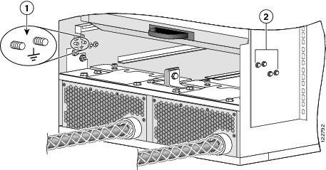
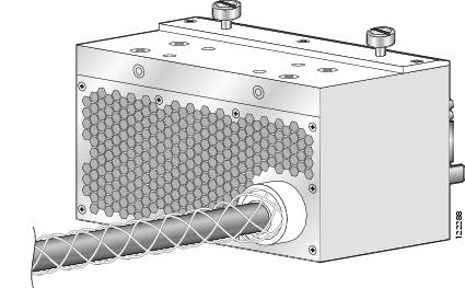
Although the router chassis has a safety earth ground connection as part of the power cabling to the PDUs, the chassis includes an option that allows you to connect the central office ground system or interior equipment ground system to the supplemental bonding and grounding receptacles on the router chassis. Two threaded ground inserts are located on the fan tray door at the rear (MSC) side of the chassis (see Figure 2-1). This ground point is also called the network equipment building system (NEBS) bonding and grounding stud.
Note
Figure 2-1 NEBS Bonding and Grounding Points (Rear of Chassis)
If you plan to connect the routing system to a network equipment building system (NEBS)-compliant supplemental bonding and grounding system at the site, you must have the following:
•
•
•
Caution
DC Power Systems
A DC-powered Cisco CRS-1 8-slot line card chassis contains two DC-input power distribution units (PDUs) and two DC power entry modules (PEMs). Each DC PDU is connected to three pairs of DC power feeds and powers a single 7500-watt DC PEM that is field replaceable. Input DC power enters the PDU and is passed to the PEM, which provides power to the components in the chassis. Each PEM has its own circuit breaker.
The DC PDU is shipped with a plastic safety cover over the input terminal block (see Figure 2-2). This safety cover is in two parts, each part held on to the PDU with a Phillips screw. We recommend removing the safety cover only when wiring and unwiring the chassis. The safety cover is slotted in such a way that the wires can only come out on the bottom portion of the cover.
Figure 2-2 DC PDU with Plastic Safety Cover
Each PDU requires three DC inputs of -48/-60 VDC (nominal), 60-amp service. The PDU accepts input DC power in the range -40.5 to -75 VDC, and has three sets of double-stud terminals (-48/-60VDC Lines and -48/-60VDC Returns) for connecting to the VDC inputs.
Each DC PDU should be connected to a different central office DC power source:
•
•
If DC power to a PDU fails, the other PDU provides enough power for the chassis. This 2N power redundancy enables the routing system to operate in spite of single power failure.
For DC power cables, we recommend that you use commensurately rated, high-strand-count copper wire cable, based on local electrical codes. These wires are not available from Cisco Systems; they are available from any commercial vendor. DC power cables must be terminated by cable lugs at the power shelf end.
Note
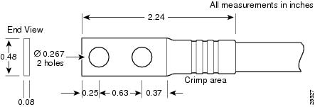
The grounding lugs should be dual-hole and able to fit over M6 terminal studs at 0.63 in (15.88-mm) centers (for example, Panduit part number LCD6-14A-L, or equivalent) (see Figure 2-3).
Figure 2-3 DC Power Grounding Cable Lug
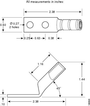
The terminal lugs (in other words, all lugs not used for grounding) should be 45-degree angled, industry-standard dual-hole compressions lugs, and able to fit over M6 terminal studs at 0.63 in (15.88-mm) centers (for example, AWG no. 2 wires, such as Panduit part number LCC2-14AH-Q or equivalent) (see Figure 2-4).
Note
Figure 2-4 DC Power Cable Lug
Note
The color coding of the source DC power cable leads depends on the color coding of the site DC power source. Typically, green or green and yellow indicates that the cable is a ground cable. Because there is no color code standard for the source DC wiring, you must ensure that the power cables are connected to the DC-input PDU terminal studs in the proper positive (+) and negative (-) polarity.
In some cases, the source DC cable leads might have a positive (+) or negative (-) label. This is a relatively safe indication of the polarity, but you must verify the polarity by measuring the voltage between the DC cable leads. When making the measurement, the positive (+) lead and negative (-) lead must always match the (+) and (-) labels on the PDU.
Caution
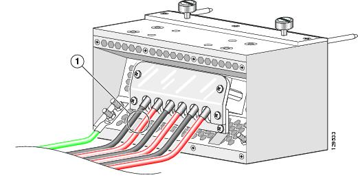
DC PDU Wiring
This section describes how to wire the DC PDU. For more detailed information on chassis DC power systems, see the "DC Power Systems" section.
Figure 2-5 DC PDU Power Cable Connections
Caution
To wire the DC PDU, follow these steps:
Step 1
Step 2
The wire should be sized according to local and national installation requirements. Use only copper wire.
Note
Step 3
Step 4
Step 5
Step 6
AC Power Systems
An AC-powered Cisco CRS-1 8-slot line card chassis contains two AC power distribution units (PDUs) and two AC rectifier modules. Each AC PDU is connected to a 3-phase (200 to 240) input VAC power source and connects to a single 7500-watt AC rectifier module that is field replaceable. Each AC rectifier module converts input AC power to the 54.5 VDC used by the Cisco CRS-1 8-slot line card chassis. Each rectifier has its own circuit breaker.
To provide 2N power redundancy for the Cisco CRS-1 8-slot line card chassis, each PDU and AC rectifier pair is connected to a different AC power source. During normal operation when both power sources are operational, both PDUs and rectifiers function together to power the chassis. However, if a power sources fails, the other power source provides the other PDU and rectifier pair with enough input power to power the chassis. This 2N power redundancy enables the routing system to operate despite the power failure.
Two versions of the AC PDU are available to accommodate AC input power in either the Delta or Wye configuration. Each PDU has a different Cisco part number. The PDUs are shipped with AC power cords that are 14 feet (4.3 m) long.
The AC PDUs have the following input VAC power requirements:
•
The Wye power cord has a 5-pin IEC 60309 plug that is rated for 400 VAC, 16 or 20 A, (3W + N + PE). The power cord plugs into a similarly rated IEC 60309 receptacle.
•
The Delta power cord has a 4-pin NEMA L15-30P plug that is rated for 250 VAC, 30 A (3W + PE). The power cord plugs into a similarly rated NEMA L15-30R locking-type receptacle.
For additional power details, see Appendix A, "CRS-1 8-Slot Line Card Chassis Specifications," or Cisco CRS-1 Carrier Routing System 8-Slot Line Card Chassis System Description.
Before Powering the Chassis Up or Down
While the line card chassis does not have a single power switch that powers the entire chassis and all its components up and down, the AC rectifier or DC PEM linkage cuts power to the chassis as a whole when both power components are turned off. Most components on the chassis, such as the power modules, MSCs, PLIMs, and fan trays can be removed or installed in the chassis while it is running.
Before you can power the chassis up, you must do the following:
Step 1
Step 2
Step 3
Step 4
Step 5
To power down the chassis entirely, you must power down each of the two power modules; you move each power switch to the off position by pulling it toward you. Both power modules must be disconnected or the PDUs unplugged to de-energize the chassis completely.
Note
Note
Converting from One Power System to Another
To convert a Cisco CRS-1 8-slot line card chassis from AC to DC power, or from DC to AC power, you must:
Step 1
Step 2
Step 3
Step 4
If you are converting from AC to DC power, you must wire the PDU properly. See the "DC Power Systems" section.
Step 5
Step 6
Caution
How to Install or Remove the Power Components
This section contains the following procedures:
Note
Note
Installing a PDU
This section describes how to install a PDU in the Cisco CRS-1 8-slot line card chassis. For information on the difference between the power types, see the "DC Power Systems" section and the "AC Power Systems" section. For complete information on regulatory compliance and safety, see Regulatory Compliance and Safety Information for the Cisco CRS-1 Carrier Routing System.
The PDU is installed into the back of the chassis. After the PDU is installed, you can slide the power modules into the chassis and connect them to the PDU to provide power to the chassis (see the "Installing a Power Module" section for details). Although there are differences among the different PDU types (AC Wye, AC Delta, and DC), they are installed in the same manner. (Figure 2-6 shows an AC Wye PDU for reference.)
Figure 2-6 AC Wye PDU
Prerequisites
Before performing this task, remove any front cosmetic covers.
Required Tools and Equipment
You need the following tools and part to perform this task:
•
•
•
•
–
–
–
Steps
To install a PDU, follow these steps:
Step 1
Step 2
Step 3
Caution
Step 4
Note
Step 5
a.
b.
c.
Step 6
What to Do Next
After performing this task, install the power modules (see the "Installing a Power Module" section), and replace any cosmetic covers.
Removing a PDU
This section describes how to remove a PDU in the Cisco CRS-1 8-slot line card chassis. For information on the difference between the power types, see the "DC Power Systems" section and the "AC Power Systems" section. For complete information on regulatory compliance and safety, see Regulatory Compliance and Safety Information for the Cisco CRS-1 Carrier Routing System.
The PDU is located at the back of the chassis. Although there are differences among the different PDU types (AC Wye, AC Delta, and DC), they are installed in the same manner (see Figure 2-7, which shows an AC Wye PDU for reference).
Figure 2-7 AC Wye PDU for the 8-Slot Chassis
Prerequisites
Before performing this task, remove any front cosmetic covers, power down and remove the power modules, and unplug the PDU. See the "Before Powering the Chassis Up or Down" section, and the "Removing a Power Module" section.
If you are removing a DC PDU, see the "DC Power Systems" section; if you are removing an AC PDU, see the "AC Power Systems" section for more information.
Required Tools and Equipment
You need the following tools to perform this task:
•
•
•
Steps
To remove an AC Wye PDU, follow these steps:
Step 1
Step 2
Step 3
Step 4
Step 5
Step 6
a.
b.
c.
Step 7
Caution
What to Do Next
After performing this task, you may install a new PDU, if needed (see the "Installing a PDU" section), and replace any cosmetic covers.
Installing a Power Module
This section describes how to install a power module in the Cisco CRS-1 8-slot line card chassis. For information on the difference between the power types, see the "DC Power Systems" section and the "AC Power Systems" section. For complete information on regulatory compliance and safety, see Regulatory Compliance and Safety Information for the Cisco CRS-1 Carrier Routing System.
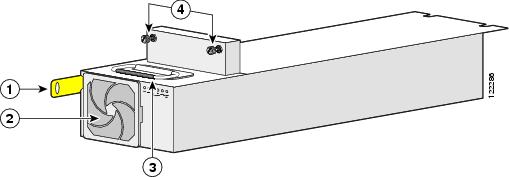
The power module is installed into the front of the chassis, and mates with the PDU that is installed on the back of the chassis (see the "Installing a PDU" section for information). Although there are differences among the different power modules (AC Wye, AC Delta, and DC), they are installed in the same manner. (Figure 2-8 shows an AC Wye power rectifier for reference.)
Figure 2-8 AC Power Rectifier
Prerequisites
Before performing this task, make sure that the PDU has been installed (see the "Installing a PDU" section) and remove any cosmetic covers.
Required Tools and Equipment
You need the following tools and part to perform this task:
•
•
•
–
–
Steps
To install a power module, follow these steps:
Step 1
Step 2
Step 3
Step 4
Caution
Step 5
Caution
Step 6
Step 7
What to Do Next
After performing this task, you may connect the PDU to the power source (see the "DC Power Systems" section and the "AC Power Systems" section) and power up the chassis (see the "Before Powering the Chassis Up or Down" section).
Removing a Power Module
This section describes how to remove a power module from the Cisco CRS-1 8-slot line card chassis. For information on the difference between the power types, see the "DC Power Systems" section and the "AC Power Systems" section. For complete information on regulatory compliance and safety, see Regulatory Compliance and Safety Information for the Cisco CRS-1 Carrier Routing System.
The power module is located on the front of the chassis, and mates with the PDU that is installed on the back of the chassis (see the "Installing a PDU" section for information). Although there are differences among the power modules (AC Wye, AC Delta, and DC), they are installed in the same manner. (Figure 2-9 shows an AC Wye power rectifier for reference.)
Figure 2-9 AC Power Rectifier
Prerequisites
Before performing this task, remove any front cosmetic covers.
Required Tools and Equipment
You need the following tools to perform this task:
•
•
Steps
To remove a power module, follow these steps:
Step 1
Step 2
Step 3
Step 4
Caution
Caution
Step 5
What to Do Next
After performing this task, you may install a new power module, if needed (see the "Installing a Power Module" section), and replace any front cosmetic covers.