Table Of Contents
Preventing Electrostatic Discharge
Overview
This installation guide describes how to install the power, air circulation, line card, and external components into and remove them from a Cisco CRS-1 Carrier Routing System 8-Slot Line Card Chassis.
This chapter introduces the Cisco CRS-1 8-slot line card chassis at the highest level. It contains illustrations of the front and back of the chassis, complete with callouts to each hardware component. For details on each subsystem discussed in this chapter, see Cisco CRS-1 Carrier Routing System 8-Slot Line Card Chassis System Description.
This chapter presents the following topics:
•
Preventing Electrostatic Discharge
Chassis Overview
The Cisco CRS-1 8-slot line card chassis can be installed in locations where the 16-slot system may not fit (for example, colocation facilities, data centers, and many Tier II and Tier III locations). The routing system consists of a single rack-mount chassis that contains the following system components:
•
•
•
•
•
The Cisco CRS-1 8-slot line card chassis has its own power and cooling subsystems.
Chassis Components
This section lists the main components of a Cisco CRS-1 8-slot line card chassis. It primarily identifies the components that are considered field-replaceable units (FRUs), but where additional detail is useful identifies subassemblies that are not field replaceable.
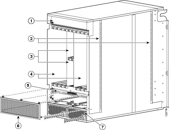
Figure 1-1 and Figure 1-2 show the line card chassis from both the front (PLIM) and rear (MSC) sides.
Figure 1-1 Front (PLIM) View of Line Card Chassis
Cable management bracket
Air filter
Chassis vertical mounting brackets
Power modules
PLIM and RP slots (RPs in middle 2 slots)
Figure 1-2 Rear (MSC) View of Line Card Chassis
Upper fan tray (beneath cover)
MSC slots
Chassis vertical mounting brackets
Lower fan tray
Switch fabric card (half-height) slots
Power distribution units (PDUs)
The Cisco CRS-1 8-slot line card chassis contains:
•
The MSC can be associated with several different PLIMs, which provide different interface speeds and technologies. The available PLIMs are:
–
–
–
–
–
•
•
The RP also monitors system alarms and controls the system fans. LEDS on the front panel indicate active alarm conditions.
•
•
The switch fabric receives user data from one MSC and PLIM pair and performs the switching necessary to route the data to the appropriate egress MSC and PLIM pair. The switch fabric is divided into eight planes that are used to evenly distribute the traffic across the switch fabric. Each switch fabric card implements two planes of the switch fabric.
•
The PLIM side of the chassis is considered the front of the chassis, where user data cables attach to the PLIMs and cool air enters the chassis. The MSC side, which is where warm air is exhausted, is considered the rear of the chassis.
Chassis Slot Numbers
This section identifies the location and slot numbers for major cards and modules (primarily the field-replaceable units) that plug into the chassis.
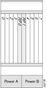
Figure 1-3 shows the slot numbering on the front (PLIM) side of the Cisco CRS-1 8-slot line card chassis.
Figure 1-3 Line Card Chassis Slot Numbering—Front (PLIM) Side
As shown, the Cisco CRS-1 8-slot line card chassis numbers on the PLIM side of the chassis include the card cage with:
•
•
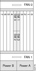
Figure 1-4 shows the slot numbers on the rear (MSC) side of the Cisco CRS-1 8-slot line card chassis.
Figure 1-4 Line Card Chassis Slot Numbers—Rear (MSC) Side
As shown, the slot numbers on the MSC side of the chassis include:
•
•
–
–
The MSC slot numbers are reversed from the PLIM slot numbers on the other side of the chassis. Because an MSC mates with its associated PLIM through the midplane, MSC slot 0 is on the far right side of the chassis looking at it from the rear (MSC) side.
PLIM slot 0 is on the far left side of the chassis, looking at if from the front (PLIM) side. MSC slot 0 and PLIM slot 0 mate with each other through the midplane, and so do all other MSC and PLIM slots (0 through 7).
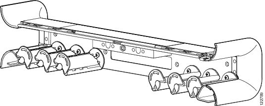
Chassis Cable Management
The Cisco CRS-1 8-slot line card chassis has cable management features for the front (PLIM) side of the chassis, just above the card cage. The horizontal cable management trays have a special telescoping feature that allows them to be extended when the chassis is upgraded with higher-density cards. This extension also helps when installing the cables in the chassis.
The cable management bracket is shown in the following figure.
Figure 1-5 Cable Management Bracket
Chassis Cooling System
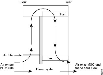
The chassis has two fan trays, each with several fans, that cool the chassis card cages. Cool air flows in at the bottom front of the chassis and flows through the chassis card cages and through the fans in the fan trays before being exhausted through the bottom rear of the chassis (see the following figure). In addition, each AC or DC power module at the bottom of the chassis has self-contained fans that pull in cool air from the front of the chassis and exhaust warm air out the rear.
A replaceable air filter is located on the front of the chassis below the PLIM card cage. Each power module also has a replaceable air filter that attaches to the module at the front (PLIM) side of the chassis. How often the air filters should be replaced depends on the facility environment. In a dirty environment, or when you start getting frequent temperature alarms, you should always check the intake grills for debris, and then check the air filters to see if they need to be replaced.
Note
Figure 1-6 Airflow Through 8-Slot Line Card Chassis
The Cisco CRS-1 8-slot line card chassis airflow volumes are:
•
•
Chassis Power System
The Cisco CRS-1 8-slot line card chassis is available with AC power distribution units (PDUs) that are configured for either AC Wye 3-phase, AC Delta 3-phase, or DC wiring. Each PDU has a different Cisco part number.
AC Wye and AC Delta PDUs basically both require 220 VAC input power:
•
•
For DC PDU, there is one type for both nominal -48 VDC and -50 VDC inputs.
Safety Guidelines
Before you perform any procedure in this document, review the safety guidelines in this section to avoid injuring yourself or damaging the equipment.
The following guidelines are for your safety and to protect equipment. The guidelines do not include all hazards. Be alert.
Note
•
•
•
Preventing Electrostatic Discharge
Electrostatic discharge (ESD) damage, which can occur when electronic cards or components are improperly handled, results in complete or intermittent failures. We recommend to use an ESD-preventive strap whenever you handle network equipment or one of its components.
Following are guidelines for preventing ESD damage:
•
•
•
•