Cisco 4G LTE Software Configuration
This document provides an overview of the software features and configuration information for Cisco Fourth-Generation (4G) Long-Term Evolution (LTE) Wireless WAN (WWAN) Enhanced High-Speed WAN Interface Cards ( EHWIC-4G-LTEs), Cisco 819 Series 4G LTE ISRs, Cisco C880 Series 4G LTE ISRs and Cisco C890 Series 4G LTE ISRs. Cisco EHWIC-4G-LTEs are single-wide 4G Wireless WAN (WWAN) EHWICs supported on Cisco Integrated Services Router Generation 2 (ISR G2). For Cisco EHWIC-4G-LTE SKUs, faceplate, and LED descriptions, see the Cisco 4G LTE Hardware Installation Guide.
Finding Feature Information
Your software release may not support all the features documented in this module. For the latest caveats and feature information, see Bug Search Tool and the release notes for your platform and software release. To find information about the features documented in this module, and to see a list of the releases in which each feature is supported, see the feature information table.
Use Cisco Feature Navigator to find information about platform support and Cisco software image support. To access Cisco Feature Navigator, go to www.cisco.com/go/cfn. An account on Cisco.com is not required.
Prerequisites for Configuring Cisco 4G LTE
- You must have 4G LTE network coverage where your router is physically placed. For a complete list of supported carriers, see the product data sheet.
- You must subscribe to a service plan with a wireless service provider and obtain a Subscriber Identity Module (SIM) card.
- You must install the SIM card before configuring the 4G LTE Wireless WAN EHWIC or Cisco 819 router.
- The standalone antenna that supports GPS capabilities must be installed for the GPS feature to work. See the Cisco 4G Indoor/Outdoor Active GPS Antenna (GPS-ACT-ANTM-SMA) (http://www.cisco.com/en/US/docs/routers/access/wireless/hardware/notes/gps_ant.html) document for installation information.
- Both GPS and NMEA features must be configured for GPS coordinates to be obtained.
Restrictions for Configuring Cisco 4G LTE
Follow these restrictions and usage guideline while configuring Cisco 4G LTE:
- Currently, cellular networks support only user initiated bearer establishment.
- Due to the shared nature of wireless communications, the experienced throughput varies depending on the number of active users or congestion in a given network.
- Cellular networks have higher latency compared to wired networks. Latency rates depend on the technology and carrier. Latency may be higher because of network congestion. Latency also depends on the signal conditions and can be higher because of network congestion.
- Any restrictions that are part of the terms of service from your carrier.
- SMS—Only one text message up to 160 characters to one recipient at a time is supported. Larger texts are automatically truncated to the proper size before being sent.
- For the router that runs the SNMP agent, you must configure appropriate access control (for example, SNMP-server community) using the Cisco IOS CLI for the NMS and agent to work properly.
- It is strongly recommended that you configure SNMP V3 with authentication/privacy when implementing SNMP SET operation.
Information about Configuring Cisco 4G LTE
Overview of Cisco 4G LTE
Cisco EHWIC-4G-LTEs are single-wide Wireless WAN (WWAN) EHWICs supported on Cisco 1110 Series routers. Cisco EHWIC-4G-LTEs operate over Fourth-Generation Long-Term Evolution (4G LTE) cellular networks and Third-Generation (3G) cellular networks. The Cisco 4G LTE WWAN EHWIC offers a highly secure, simplified, and cost-effective WAN alternative to DSL or Frame Relay. In areas where terrestrial broadband services (cable, DSL, or T1) are not available or are expensive, 4G LTE WWAN connectivity can be a viable alternative. Using the integrated services available on the Cisco 1110 series routers, Cisco 4G LTE Wireless WAN EHWICs can provide instant and mobile communications during disasters and service outages.
Cisco 4G LTE EHWICs support the following 4G/3G modes:
- 4G LTE —4G LTE mobile specification provides multi-megabit bandwidth, more efficient radio network, latency reduction, and improved mobility. LTE solutions target new cellular networks. These networks initially support up to 100 Mb/s peak rates in the downlink and up to 50 Mb/s peak rates in the uplink. The throughput of these networks is higher than the existing 3G networks
- 3G Evolution High-Speed Packet Access (HSPA/HSPA+) —HSPA is a UMTS-based 3G network. It supports High-Speed Downlink Packet Access (HSDPA) and High-Speed Uplink Packet Access (HSUPA) data for improved download and upload speeds. Evolution High-Speed Packet Access (HSPA+) supports Multiple Input/Multiple Output (MIMO) antenna capability.
- 3G Evolution-Data Optimized (EVDO or DOrA) Mode —EVDO is a 3G telecommunications standard for the wireless transmission of data through radio signals, typically for broadband Internet access. DOrA refers to EVDO Rev-A. EVDO uses multiplexing techniques including Code Division Multiple Access (CDMA), as well as Time Division Multiple Access (TDMA), to maximize both individual users' throughput and the overall system throughput.
The following table describes the Cisco 4G WWAN EHWIC product SKUs.
|
Cisco 4G EHWIC |
Description |
Mode |
Operating Regions |
Frequency Band |
|---|---|---|---|---|
|
EHWIC-4G-LTE-V |
EHWIC-4G-LTE-V is a dedicated Multimode LTE SKU for Verizon Wireless networks and it is backwards compatible with these technologies:
|
|
North America |
|
|
EHWIC-4G-LTE-A |
EHWIC-4G-LTE-A is a dedicated Multimode LTE SKU for AT&T Wireless networks and it is backwards compatible with these technologies:
|
|
North America |
For LTE:
For UMTS, HSPA+ and HSPA:
For GSM, EDGE and GPRS:
|
|
EHWIC-4G-LTE-G |
EHWIC-4G-LTE-G is a dedicated Multimode LTE SKU for global wireless networks and it is backwards compatible with these technologies:
|
|
Global |
For LTE:
For UMTS/HSPA+/HSPA:
For GSM/EDGE/GPRS:
|
|
EHWIC-4G-LTE-JP |
EHWIC-4G-LTE-JP is a dedicated Multimode LTE SKU for NTT Docomo Japan, and is based on the Sierra Wireless MC7700 modem. EHWIC-4G-LTE-JP is backward compatible with these technologies:
|
|
Japan |
For LTE: 2100 MHz (band 1) For UMTS/HSPA+:
|
|
EHWIC-4G-LTE-BE |
EHWIC-4G-LTE-BE is a dedicated Multimode LTE SKU for Canada, and is based on the Sierra Wireless MC7700 modem. EHWIC-4G-LTE-BE is backward compatible with these technologies:
|
|
Canada |
For LTE: AWS band 4 For UMTS/HSPA+:
|
|
EHWIC-4G-LTE-AU |
EHWIC-4G-LTE-AU is a dedicated Multimode LTE SKU for wireless networks in Australia and New Zealand. EHWIC-4G-LTE-AU comes with a Sierra Wireless MC7304 modem. |
|
Australia and New Zealand |
For LTE:
For UMTS/HSPA+/HSPA:
For GSM/EDGE/GPRS:
|
|
EHWIC-4G-LTE-ST |
Dedicated Multimode LTE SKU for Sprint Wireless networks. This comes with a Sierra Wireless MC7350 modem. |
|
North America (Sprint) |
LTE:
3G:
2G:
|
|
EHWIC-4G-LTE-VZ |
Dedicated Multimode LTE SKU for Verizon Wireless networks. This comes with a Sierra Wireless MC7350 modem. |
|
North America (Verizon) |
LTE:
3G:
2G:
|
|
EHWIC-4G-LTE-CA |
Dedicated Multimode LTE SKU for Wireless networks in Canada. This comes with a Sierra Wireless MC7354 modem. |
|
Canada |
LTE:
3G (UMTS, HSPA+, HSPA):
2G (GSM, EDGE, GPRS):
|
|
EHWIC-4G-LTE-AT |
Dedicated Multimode LTE SKU for AT & T Wireless networks. This comes with a Sierra Wireless MC7354 modem. |
|
North America (AT&T) |
LTE:
3G (UMTS, HSPA+, HSPA):
2G (GSM, EDGE, GPRS):
|
|
EHWIC-4G-LTE-GB |
Dedicated Multimode LTE SKU for global Wireless networks. This comes with a Sierra Wireless MC7304 modem. |
|
Global (except Australia and New Zealand) |
For LTE:
For UMTS, HSPA+, HSPA:
For GSM, EDGE, GPRS:
|
|
EHWIC-LTE-LA |
Dedicated Multimode LTE SKU for Latin American Wireless networks. This comes with a Sierra Wireless MC7430 modem. |
|
Latin America |
For FDD LTE:
For TDD LTE:
For UMTS, HSPA+, HSPA:
|
|
EHWIC-LTE-CI |
Dedicated Multimode LTE SKU for Wireless networks in India and China. This comes with a Sierra Wireless MC7430 modem. |
|
India and China |
For FDD LTE:
For TDD LTE:
For UMTS, HSPA+, HSPA:
|
|
EHWIC-LTE-JN |
Dedicated Multimode LTE SKU for Wireless networks in Japan. This comes with a Sierra Wireless MC7430 modem. |
|
Japan |
For FDD LTE:
For TDD LTE:
For UMTS, HSPA+, HSPA:
|
The following table lists the different 4G LTE SKUs available for the Cisco 1110 series routers:
|
SKU ID |
Description |
Mode |
Operating Regions |
Frequency Band |
||
|---|---|---|---|---|---|---|
|
C819HG-4G-V-K9 |
C819HG-4G-V-K9 is a dedicated Multimode LTE SKU for Verizon Wireless networks and comes with a Sierra Wireless MC7750 modem. C819HG-4G-V-K9 is a hardened Cisco 819 Series Router. |
LTE—DOrA |
North America |
For LTE: 700 MHz (band 13) For CDMA 1xRTT, 1xEVDO Rev A:
|
||
|
C819G-4G-V-K9 |
C819G-4G-V-K9 is a dedicated Multimode LTE SKU for Verizon Wireless networks and comes with a Sierra Wireless MC7750 modem. C819G-4G-V-K9 is a non-hardened Cisco 819 Series Router. |
LTE—DOrA |
North America |
For LTE: 700 MHz (band 13) For CDMA 1xRTT, 1xEVDO Rev A:
|
||
|
C819HG-4G-A-K9 |
C819HG-4G-A-K9 is a dedicated Multimode LTE SKU for AT & T Wireless networks and comes with a Sierra Wireless MC7700 modem. C819HG-4G-A-K9 is a hardened Cisco 819 Series Router. |
LTE—HSPA+/ HSPA/UMTS/ EDGE/GPRS |
North America |
For LTE:
For UMTS/HSPA+/HSPA:
For GSM/EDGE/GPRS:
|
||
|
C819G-4G-A-K9 |
C819G-4G-A-K9 is a dedicated Multimode LTE SKU for AT&T Wireless networks and comes with a Sierra Wireless MC7700 modem. C819G-4G-A-K9 is a compact non-hardened Cisco 819 Series Router. |
LTE—HSPA+/ HSPA/UMTS/ EDGE/GPRS |
North America |
For LTE:
For UMTS/HSPA+/HSPA:
For GSM/EDGE/GPRS:
|
||
|
C819HG-4G-G-K9 |
C819HG-4G-G-K9 is a dedicated Multimode LTE SKU for global wireless networks and comes with a Sierra Wireless MC7710 modem. C819HG-4G-G-K9 is a hardened Cisco 819 Series Router. |
LTE—HSPA+/ HSPA/UMTS/ EDGE/GPRS |
Global |
For LTE:
For UMTS/HSPA+/HSPA:
For GSM/EDGE/GPRS:
|
||
|
C819G-4G-G-K9 |
C819G-4G-G-K9 is a dedicated Multimode LTE SKU for global wireless networks and comes with a Sierra Wireless MC7710 modem. C819G-4G-G-K9 is a non-hardened Cisco 819 Series Router. |
LTE—HSPA+/ HSPA/UMTS/ EDGE/GPRS |
Global |
For LTE:
For UMTS/HSPA+/HSPA:
For GSM/EDGE/GPRS:
|
||
|
C819G-4G-GA-K9 |
C819G-4G-GA-K9 is a dedicated Multimode LTE SKU for global wireless networks and comes with a Sierra Wireless MC7304 modem. C819G-4G-G-K9 is a non-hardened Cisco 819 Series Router. |
LTE—HSPA+/ HSPA/UMTS/ EDGE/GPRS |
Global (Europe, Australia and New Zealand) |
For LTE:
For UMTS/HSPA+/HSPA:
For GSM/EDGE/GPRS:
|
||
|
C819G-4G-NA-K9 |
Non-hardened Cisco 819 router with multi-mode LTE feature for AT & T wireless networks. This comes with a Sierra Wireless MC7354 modem. |
|
North America (AT&T, Bell-Canada, Roger, Telus, and other GSM/LTE operators in USA and Canada) |
LTE:
UMTS, HSPA+, HSPA:
GSM, EDGE, GPRS:
|
||
|
C819G-4G-ST-K9 |
Non-hardened Cisco 819 router with multi-mode LTE feature for Sprint wireless networks. This comes with a Sierra Wireless MC7350 modem. |
|
North America (Sprint) |
LTE:
3G:
2G:
|
||
|
C819G-4G-VZ-K9 |
Non-hardened Cisco 819 router with multi-mode LTE feature for Verizon wireless networks. This comes with a Sierra Wireless MC7350 modem. |
|
North America (Verizon) |
LTE:
3G:
2G:
|
||
|
C819GW-LTE-MNA-AK9 |
C819GW-LTE-MNA-AK9 is a dedicated Multimode LTE SKU for North America wireless networks and comes with a Sierra Wireless MC7354MNA modem. C819GW-LTE-MNA-AK9 is a non-hardened Cisco 819 Series Router. For 3GPP complaint, the extended temperature range for this SKU is -15 to 50C. For non-3GPP complaint, it is -15 to 55C. Dual SIMs in this SKU provide high reliability and cellular multihoming support for LTE and HSPA-based networks using the common FW technology within the same region. Dual SIMs in the North American SKUs provide switchover with different FW technology.
|
|
North America |
For LTE:
For HSPA+:
For CDMA and EVDO Revision A:
For EDGE/GPRS/GSM:
|
||
|
C819GW-LTE-GA-EK9 |
C819GW-LTE-GA-EK9 is a dedicated Multimode LTE SKU for global wireless network and comes with a Sierra Wireless MC7304 modem. C819GW-LTE-GA-EK9 is a non-hardened Cisco 819 Series Router. For 3GPP complaint, the extended temperature range for this SKU is -15 to 50C. For non-3GPP complaint, it is -15 to 55C. Dual SIMs in this SKU provide high reliability and cellular multihoming support for LTE and HSPA-based networks using the common FW technology within the same region. Dual SIMs provide switchover with different FW technology.
|
|
Global (Europe and Australia) |
For LTE:
For HSPA+:
For EDGE/GPRS/GSM:
|
||
|
C819G-LTE-MNA-K9 |
C819G-LTE-MNA-K9 is a dedicated Multimode LTE SKU for global wireless network and comes with a Sierra Wireless MC7354-MNA modem. C819G-LTE-MNA-K9 is a non-hardened Cisco 819 Series Router. For 3GPP complaint, the extended temperature range for this SKU is -15 to 50C. For non-3GPP complaint, it is -15 to 55C. Dual SIMs in this SKU provide high reliability and cellular multihoming support for LTE and HSPA-based networks using the common FW technology within the same region. Dual SIMs provide switchover with different FW technology.
|
|
Global (Europe and Australia) |
LTE:
3G(UMTS,HSPA+,HSPA):
2G(GSM,EDGE,GPRS):
|
||
|
C819G-LTE-LA-K9 |
C819G-LTE-LA-K9 is a dedicated Multimode LTE SKU for Latin American wireless networks and comes with a Sierra Wireless MC7430 modem. |
|
Latin America/APAC |
For FDD LTE:
For TDD LTE:
For UMTS, HSPA+, HSPA:
|
||
|
C819GW-LTE-LA-CK9 |
C819G-LTE-LA-K9 is a dedicated Multimode LTE SKU for Latin American wireless networks and comes with a Sierra Wireless MC7430 modem. |
|
Latin America/APAC |
For FDD LTE:
For TDD LTE:
For UMTS, HSPA+, HSPA:
|
||
|
C819GW-LTE-LA-QK9 |
C819G-LTE-LA-QK9 is a dedicated Multimode LTE SKU for Latin American wireless networks and comes with a Sierra Wireless MC7430 modem. |
|
Latin America/APAC |
For FDD LTE:
For TDD LTE:
For UMTS, HSPA+, HSPA:
|
||
|
C819GW-LTE-LA-NK9 |
C819G-LTE-LA-NK9 is a dedicated Multimode LTE SKU for Latin American wireless networks and comes with a Sierra Wireless MC7430 modem. |
|
Latin America/APAC |
For FDD LTE:
For TDD LTE:
For UMTS, HSPA+, HSPA:
|
The following table lists the different 4G LTE SKUs available for the Cisco 880 and Cisco 890 series ISRs.
|
SKU ID |
Mode |
Operating Region |
Frequency Band |
Description |
|---|---|---|---|---|
|
C881G-4G-GA-K9 |
|
Global (Europe, New Zealand, and Australia) |
LTE:
3G (UMTS, HSPA+, HSPA):
2G (GSM, EDGE, GPRS):
|
Cisco 880 Series ISR with Multimode LTE feature for global wireless networks. C881G-4G-GA-K9 comes with a Sierra Wireless MC7304 modem. |
|
C887VAG-4G-GA-K9 |
|
Global (Europe, New Zealand, and Australia) |
LTE:
3G (UMTS, HSPA+, HSPA):
2G (GSM, EDGE, GPRS):
|
Cisco 880 series ISR with Multimode LTE feature for global wireless networks. C887VAG-4G-GA-K9 comes with a Sierra Wireless MC7304 modem. |
|
C896VAG-LTE-GA-K9 |
|
Global (Europe, New Zealand, and Australia) |
LTE:
3G (UMTS, HSPA+, HSPA):
2G (GSM, EDGE, GPRS):
|
Cisco 890 series ISR with Multimode LTE feature for global wireless networks. C896VAG-LTE-GA-K9 comes with a Sierra Wireless MC7304 modem. |
|
C897VAG-LTE-GA-K9 |
|
Global (Europe, New Zealand, and Australia) |
LTE:
3G (UMTS, HSPA+, HSPA):
2G (GSM, EDGE, GPRS):
|
Cisco 890 series ISR with Multimode LTE feature for global wireless networks. C897VAG-LTE-GA-K9 comes with a Sierra Wireless MC7304 modem. |
|
C897VAMG-LTE-GA-K9 |
|
Global (Europe, New Zealand, and Australia) |
LTE:
3G (UMTS, HSPA+, HSPA):
2G (GSM, EDGE, GPRS):
|
Cisco 890 series ISR with Multimode LTE feature for global wireless networks. C897VAMG-LTE-GA-K9 comes with a Sierra Wireless MC7304 modem. |
|
C898EAG-LTE-GA-K9 |
|
Global (Europe, New Zealand, and Australia) |
LTE:
3G (UMTS, HSPA+, HSPA):
2G (GSM, EDGE, GPRS):
|
Cisco 890 series ISR with Multimode LTE feature for global wireless networks. C898EAG-LTE-GA-K9 comes with a Sierra Wireless MC7304 modem. |
|
C899G-LTE-GA-K9 |
|
Global (Europe, New Zealand, and Australia) |
LTE:
3G (UMTS, HSPA+, HSPA):
2G (GSM, EDGE, GPRS):
|
Cisco 890 series ISR with Multimode LTE feature for global Wireless networks. C899G-LTE-GA-K9 comes with a Sierra Wireless MC7304 modem. |
|
C899G-LTE-VZ-K9 |
|
North America (Verizon) |
LTE:
3G:
2G:
|
Cisco 890 series ISR with Multimode LTE feature for Verizon wireless networks. C899G-LTE-VZ-K9 comes with a Sierra Wireless MC7350 modem. |
|
C899G-LTE-NA-K9 |
|
North America (AT&T, Bell-Canada, Roger, Telus, and other GSM/LTE operators in USA and Canada) |
LTE:
3G (UMTS, HSPA+, HSPA):
2G (GSM, EDGE, GPRS):
|
Cisco 890 series ISR with Multimode LTE feature for wireless networks in USA and Canada. C899G-LTE-NA-K9 comes with a Sierra Wireless MC7354 modem. |
|
C899G-LTE-ST-K9 |
|
North America (Sprint) |
LTE:
3G:
2G:
|
Cisco 890 series ISR with Multimode LTE feature for Sprint wireless networks. C899G-LTE-ST-K9 comes with a Sierra Wireless MC7350 modem. |
|
C899G-LTE-JP-K9 |
|
Global (Japan) |
LTE:
3G (UMTS, HSPA+, HSPA):
2G (GSM, EDGE, GPRS):
|
Cisco 890 series ISR with Multimode LTE feature for global wireless networks. C899G-LTE-JP-K9 comes with a Sierra Wireless MC7330 modem. |
|
C897VAG-LTE-LA-K9 |
C897VAG-LTE-LA-K9 is a dedicated Multimode LTE SKU for Latin American wireless networks and comes with a Sierra Wireless MC7430 modem. |
|
Latin America |
For FDD LTE:
For TDD LTE:
For UMTS, HSPA+, HSPA:
|
|
C898EAG-LTE-LA-K9 |
C898EAG-LTE-LA-K9 is a dedicated Multimode LTE SKU for ASEAN wireless networks and comes with a Sierra Wireless MC7430 modem. |
|
ASEAN |
For FDD LTE:
For TDD LTE:
For UMTS, HSPA+, HSPA:
|
|
C899G-LTE-LA-K9 |
C899G-LTE-LA-K9 is a dedicated Multimode LTE SKU for Latin American wireless networks and comes with a Sierra Wireless MC7430 modem. |
|
Latin America and APAC |
For FDD LTE:
For TDD LTE:
|
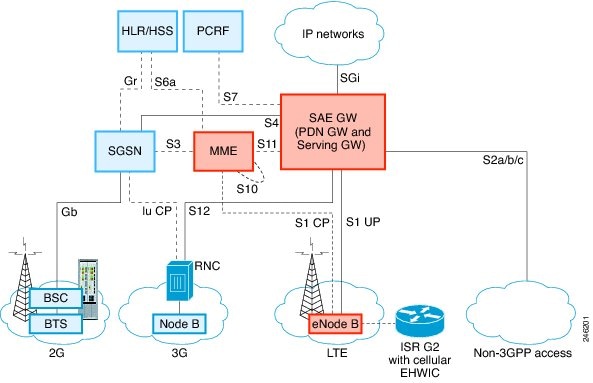
The following figure explains the 4G LTE packet core network architecture.
|
Gateways |
The Serving Gateway (SGW) routes and forwards user data packets, while also acting as the mobility anchor for the user plane, and is the anchor for mobility between LTE and other 3GPP technologies. The Packet Data Network (PDN) Gateway (PGW) provides connectivity from the User Equipment (UE) to external packet data networks by being the point of exit and entry of traffic for the UE. A UE may have simultaneous connectivity with more than one PGW for accessing multiple PDNs. The PGW performs policy enforcement, packet filtering for each user, charging support, lawful interception, and packet screening. Another key role of the PGW is to act as the anchor for mobility between 3GPP and non-3GPP technologies such as WiMAX and 3GPP2 (CDMA 1X and EvDO). The System Architecture Evolution GW (SAE GW) is the entity that covers the PGW and SGW functionality in the Evolved Packet Core (EPC). |
|
RNC |
The Radio Network Controller (RNC) is responsible for controlling the Radio Access Network (RAN) that are connected to it. The RNC carries out radio resource management and some of the mobility management functions and is the point where encryption is done before user data is sent to and from the mobile. The RNC connects to the Circuit-Switched Core Network through the Media Gateway (MGW). |
|
BTS |
Base Transceiver Station. |
|
BSC |
Base Station Controller. |
|
SGSN |
Service GPRS Support Node. |
Cisco 4G LTE Features
Cisco 4G LTE WWAN EHWICs, Cisco 1110 Series 4G LTE routers support the following major features:
- Global Positioning System (GPS) and National Marine Electronics Association (NMEA) streaming.
- 4G Short Message Service (SMS)
- 3G/4G Simple Network Management Protocol (SNMP) MIB
- Auto-switch failover between primary and backup link
- Multichannel-interface-processor (MIP) profile configuration
- Remotely initiated data callback using voice
- Remotely initiated data callback using Short Message Service (SMS)
- Remote firmware upgrade over 4G LTE
- Virtual diagnostic monitoring
- Mobile Equipment Personalization (MEP) lock and unlock capabilities
- SIM lock and unlock capabilities
- Multiple PDN Contexts
- Quality of Service
4G GPS and NMEA
The Global Positioning System (GPS) feature is enabled by default on the supported Cisco 1110 Series routers and Cisco 4G LTE EHWICs to provide the geographical location.
Active GPS is supported on the SubMiniature version A (SMA) port. Active GPS antenna is supported only in the standalone mode. An Active GPS antenna includes a built-in Low-Noise Amplifier that provides sufficient gain to overcome coaxial cable losses while providing the proper signal level to the GPS receiver. Active GPS antennae require power from the GPS receiver SMA port to operate. See the Example: Connecting to a Server Hosting a GPS Application section for more information.
National Marine Electronics Association (NMEA) streams GPS data either from a 4G EHWIC or a Cisco 1110 series router through a virtual COM port and a TCP/IP Ethernet connection to any marine device (such as a Windows-based PC) that runs a commercially available GPS-based application.
The following GPS and NMEA features are supported on the Cisco 1110 series routers:
- GPS standalone mode (satellite-based GPS).
- Cisco IOS CLI display coordinates.
- Virtual and physical serial ports can export NMEA-formatted GPS data.
- External application displays router map location.
- Objects in the CISCO-WAN-3G-MIB supports GPS and NMEA features.
- The Cisco 4G LTE EHWIC supports only the IP NMEA streaming option.
- The Cisco 1110 series routers can support either IP or serial NMEA streaming options.
 Note |
Assisted GPS mode is not supported. |
For instructions on setting up the GPS antenna, see the Cisco 4G Indoor/Outdoor Active GPS Antenna (GPS-ACT-ANTM-SMA) document.
For information on Customer Advisory on GPS rollover, see the Mandatory firmware upgrade for all MC73xx Modems document.
Connecting to a Server Hosting a GPS Application
You can feed the NMEA data to a remote server that hosts the GPS application. The server can be connected to the router either directly using an Ethernet cable or through a LAN or WAN network. If the application supports serial port, run a serial port emulation program to create a virtual serial port over the LAN or WAN connection.
Note |
Microsoft Streets & Trips is a licensed software that you can download from the Microsoft website. |
To connect a Cisco 1110 series router through IP to a PC running Microsoft Streets & Trips, perform the following steps:
- Connect the PC to the router using an Ethernet cable.
- Ensure that the PC and router can ping.
- Launch the serial port redirector on the PC.
- Use the show line command in the privileged EXEC mode to locate the NMEA port on the router.
- Create a virtual serial port that connects to the NMEA port on the router.
- Launch Microsoft Streets & Trips on your PC.
- Select the GPS Menu.
- Click Start Tracking.
- If you have acquired a location fix from the show cellular gps command output on the router, the current location is plotted on the graph, and a reddish brown dotted cursor with a circle around it is seen on the map.
Note |
If you have not acquired a location fix, the Microsoft application times out and disconnects. |
Short Message Service (SMS) Capabilities
Cisco 4G LTE EHWICs and Cisco 1110 series routers support receiving, transmitting, archiving, and deleting of SMS messages. This support includes the ability to view up to 25 received texts, and archive more messages in a custom file location. SMS is supported on multiple carriers. Cisco 4G LTE EHWICs and Cisco 1110 series routers also have the capability to revert from LTE SMS to 3G and 2G SMS technology if necessary.
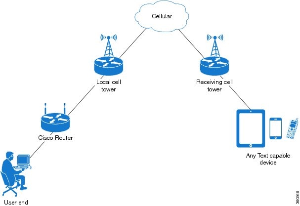
A sending device behind a Cisco 4G LTE router transmits an SMS text message over the 4G cellular link through cellular towers until it the message reaches the recipient’s router, which then notifies the recipient device, such as a cell phone. The receiving device uses the same process to return a reply to the sending device. The following figure describes the flow from a mobile device to a sending device. For SMS transmission to work, end users must have a text-capable device, and optionally, a text plan. If end users do not have a text plan, standard SMS rates apply to their text transmissions.
The SMS-initiated Data Callback feature allows customers to set up a data connection by sending a text message to the Cisco 4G LTE router and includes the message screening functionality using the originating number to improve feature security and eliminate unauthorized callback requests.
Using a SIM Card
Cisco 4G LTE EHWICs and Cisco 1110 series routers need an active SIM card provided by a service provider. The SIM cards are usually provided in an unlocked state so that it can be used without a Personal Identification Number (PIN). If the SIM is unlocked, it can be inserted into an EHWIC and used without an authorization code.
The SIM can be initially locked with a PIN code (4 to 8 digits s long) defined by the service provider. Contact your service provider for the PIN code.
The SIM-Lock feature allows a SIM to be locked or unlocked with a PIN code so that it is used only in an authorized device. Perform the SIM lock and unlock procedures using the Cisco IOS CLI through a console or Telnet/SSH to the router.
After the SIM is locked, it cannot initiate a call unless authentication is done using the same PIN. Authentication is done automatically by Cisco IOS through configuration of the PIN. This mandatory configuration for automatic SIM authentication is done using the Cisco IOS CLI as part of the router startup configuration.
After the Cisco IOS configuration is in place, the router can initiate an LTE connection. The router uses the configured PIN to authenticate prior to the LTE connection. If the Cisco IOS PIN configuration is missing or if the PIN is incorrect, the SIM authentication will fail and the connection will not be initiated.
If the locked SIM is moved to a different router or to another device, or if the EHWIC in which the locked SIM resides is moved to a different EHWIC slot in the same router, the router configuration should be changed. The configuration is associated with the cellular controller that is specific to a router EHWIC slot number. This will ensure that the SIM card will not be used in any unauthorized device, or, if there are multiple LTE EHWICs in a single ISR, that the appropriate PIN is applied to each LTE EHWIC/SIM. An authentication command (with the same PIN used to lock the SIM) must be defined on the new device or on the new cellular controller slot to successfully initiate the LTE connection.
Note |
It is very important to use the correct PIN after it is configured. The SIM card will be blocked if the wrong PIN is entered three consecutive times on a locked SIM during authentication or when trying to unlock a locked SIM. You can unblock a blocked SIM card using the PUK code. Contact your service provider for the PUK code. Use the cellular slot lte sim unblock PUK -code new -PIN -code command to unblock the SIM. |
The following procedures are used to configure a SIM:
Data Account Provisioning
One or more modem data profiles can be created to provision a modem on a 3G or 4G EHWIC. An active wireless account with a service provider with one or more (dual) SIM cards must be installed. The modem data profile is preconfigured on the modem.
The following tasks are used to verify the signal strength and service availability of the modem and to create, modify, and delete modem data profiles:
IP Multimedia Subsystem Profiles
IP Multimedia Subsystem (IMS) profiles establish a session, and are a part of the modem configuration and are stored in the modem's NVRAM. An IMS network is an access-independent and standard-based IP connectivity service that enables different types of multimedia services to end users using common Internet-based protocols. See Creating, Modifying, or Deleting Modem Data Profiles, for more information.
Usage Guidelines for Creating, Modifying, or Deleting Data Profiles
You can create multiple profiles on Cisco 4G LTE EHWICs and Cisco 1110 series routers. The following are the default Internet profile numbers for some of the modems:
- MC7700—Profile 1
- MC7710—Profile 1
- MC7750—Profile 3
- MC7304—Profile 1
- MC7350—Profile 3
- MC7354—Profile 1
- MC7430—Profile 1
For information on supported modems on each SKU, see the tables in the Overview of Cisco 4G LTE.
The maximum number of profiles that can be created for each modem is given as follows:
- MC7700—Up to 16 profiles
- MC 7710—Up to 16 profiles
- MC7750—Up to 6 profiles
- MC7304—Up to 16 profiles
- MC7350—Up to 6 profiles
- MC7354—Up to 16 profiles
- MC7430—Up to 16 profiles
The default data profile numbers for the various modem SKUs are given as follows:
-
- MC7700, MC7710, MC7354, MC7304 – Profile 1
- MC7750, MC7350– Profile 3
- MC7430–Profile 1
The data profile is displayed by using the show cellular unit profile command with an asterisk(*).
Follow these guidelines while you configure a data profile:
- In most cases, you do not have to make any profile-related changes if your modem comes with a data profile, for instance, AT&T, Sprint and Verizon.
- If any profile parameter changes are required for a connection type, the changes will most likely be carried out in the default profiles.
- To configure different profile types and use them for a different connection, you can create separate profiles with different parameters (for instance, APN names). Note that only one profile is active at a given time.
- Use the show cellular profile command to view the data profile. An asterisk(*) is displayed against the data profile.
- The data profile is used to set up a data call. If you want to use a different profile, that profile needs to be made the default one. Use the lte sim data-profile number command to change the default profile.
- To verify the completed sets of 3GPP and 3GPP2 profiles, enable the debug cellular 0/x/0 message profile command and then enter the show cellular 0 profile command. This debug command is applicable for 4G LTE SKUs with MC7750 and MC7350 modems.
If you are using the MC7750(EHWIC-LTE-4G-V and C819-LTE-4G-V), avoid modifying the ims profile (Profile 1 displayed in the show command with a ** against it). Typically, you have to modify Profile 3 for an APN update.
Note |
For the EHWIC, the unit argument identifies the router slot, WIC slot, and port separated by slashes (0/0/0). For the Cisco 1110 Series 4G LTE routers, the unit argument identifies slot “0” for all commands. |
4G LTE LEDs
The following table describes 4G LTE EHWIC and Cisco 1110 series LED behavior:
|
LED |
Color |
Description |
|---|---|---|
|
SYS |
Yellow |
FPGA download is complete. |
|
Green (blinking) |
ROMMON is operational. |
|
|
Green (solid) |
Cisco IOS is operational. |
|
|
Green (four blinks during bootup) |
Reset button has been pushed during the bootup. |
|
|
Off |
After powering up, when FPGA is being downloaded (in ROMMON). |
|
|
ACT |
Green |
Network activity on FE switch ports, GE WAN port, 3G cellular interface, and serial interfaces. |
|
Off |
No network connectivity. |
|
|
WWAN |
Green Solid —On |
Module is powered on and connected, but is not transmitting or receiving. |
|
Green (slow blinking) —On 5sec, Off 200ms |
Module is powered on and searching for connection. |
|
|
Green (fast blinking) —On 400ms, Off 100ms |
Module is transmitting or receiving. |
|
|
Green (blinking) —On 500ms, Off 500ms |
Module in Low Power Mode. Modem radio is OFF |
|
|
Off |
Module is not powered. |
|
|
GPS - EHWIC |
Green (solid) |
GPS coordinates are obtained. |
|
Off |
GPS is disabled, GPS is enabled without GPS mode and NMEA configuration, or GPS is acquiring. |
|
|
GPS - 819 ISR |
Green (solid) |
GPS coordinates are obtained. |
|
Green (blinking) |
GPS is acquiring. |
|
|
Off |
GPS is disabled or GPS is enabled without GPS mode and NMEA configuration. |
|
|
RSSI |
Green (solid) |
Signal > –60 dBm Very strong signal |
|
Green (three blinks and then a long pause) |
Signal <= –60 to 74 dBm Strong signal |
|
|
Green (two blinks and then a long pause) |
Signal <= –75 to 89 dBm Fair signal |
|
|
Green (one blink and then a long pause) |
Signal <= –90 to 109 dBm Marginal signal |
|
|
Off |
Signal <= –110 dBm Unusable signal |
|
|
SIM |
Green / Yellow (one green blink followed by two yellow blinks) |
SIM in slot 0 is active, SIM in slot 1 is not. |
|
Yellow / Green (one yellow blink followed by two green blinks) |
SIM in slot 1 is active, SIM in slot 0 is not. |
|
|
Off / Green (two green blinks and then a pause) |
No SIM in slot 0, SIM present in slot 1. |
|
|
Green / Off (slow single green blink and then a pause) |
SIM present in slot 0, no SIM in slot 1. |
|
|
Off / Off |
No SIM present in either slots. |
|
|
3G/4G |
Green (one blink and then a pause) |
For 1xRTT, EGPRS, or GPRS service. |
|
Green (two blinks and then a pause) |
For EVDO, EVDO/1xRTT, or UMTS service. |
|
|
Green (three blinks and then a pause) |
For EVDO/1xRTT RevA, HSPA, or HSUPA/HSDPA service. |
|
|
Green (four blinks and then a pause) |
For HSPA+ service. |
|
|
Green (Solid) |
For 4G/LTE service. |
|
|
Off |
No service. |
Multiple PDN Contexts
This feature enables router to connect to multiple (currently two) packet data networks. This allows users to enable different features independently on each PDN. For instance, the first PDN can be used for public Internet access and the second one for VPN connectivity; each PDN has its own set of IP addresses and QoS characteristics.
During the initialization of the router, two cellular interfaces corresponding to the two PDNs are created:
-
cellular 0/x/0 and cellular 0/x/1 on EHWIC
-
cellular 0 and cellular 1 on C8xx
These interfaces can be viewed as two logical interfaces using the same radio resources.
Note |
This feature is supported on Global, Australia, Canada, and AT&T SKUs. This feature is not supported on Sprint and Verizon SKUs. |
Note |
Here onwards, the interface cellular 0/x/0 on EHWIC and cellular 0 on C8xx are referred as the first PDN, and cellular 0/x/1 on EHWIC and cellular 1 on C8xx as the second PDN. |
The first step, in bringing up the two PDNs, is applying the configuration on both the cellular interfaces and their corresponding lines, in order to make two simultaneous data calls.
The next step is associating the data-bearer profile with its corresponding cellular interface or PDN. It is sufficient to associate the profile for just the first PDN under the controller cellular configuration. Note that the second PDN assumes a profile that is just one above the profile used for the first PDN. For example, if the first PDN uses profile 1, the second PDN uses profile 2 automatically when the call is initiated for the second one.
After the interesting traffic is routed through these cellular interfaces, data calls are initiated and each interface is assigned its own IP and DNS addresses provided by the cellular network. Note that both PDNs share radio resources. Therefore, any throughput measurement needs to take into account the aggregate throughput on both PDNs, instead of just one.
Call History
Call history maintains the history of the last three calls. The following details are recorded in the call history:
- Tx/Rx bytes
- Reason for disconnecting the call
- Duration of the call
- Who disconnected the call; User, Modem, or Network
Use the show cellular unit connection history command to display the call history. Note that this feature has dependency on modem firmware and SDK used.
The following example shows the output of the command when the call connection is up:
c1921-mc7304#show cell 0/1/0 connection call-history
Start Time                    Stop Time                     Duration
Fri Nov  7 10:30:11 2014      Fri Nov  7 10:31:28 2014      77 seconds
Call disconnect reason
Call end mode =
Session disconnect reason type = (0)
Session disconnect reason = (0)
Fri Nov  7 10:33:20 2014      ongoing
The following example shows the output of the command when the call connection is down:
1921-mc7304#show cell 0/1/0 connection call-history
Start Time                    Stop Time                     Duration
Fri Nov  7 10:30:11 2014      Fri Nov  7 10:31:28 2014      77 seconds
Call disconnect reason
Call end mode =
Session disconnect reason type = (0)
Session disconnect reason = (0)
Fri Nov  7 10:33:20 2014      Fri Nov  7 10:36:14 2014      174 seconds
Call disconnect reason
Call end mode =
Session disconnect reason type = (0)
Session disconnect reason = (0)
Dual SIM
The Dual SIM feature provides a failover mechanism in case the active SIM loses connectivity to the network.
Note |
Dual SIM is supported only on Cisco 819 Series 4G LTE ISRs, Cisco C880 Series 4G LTE ISRs and Cisco C890 Series 4G LTE ISRs. Dual SIM is not supported on EHWICs although modular ISRs can have multiple 4G EHWICs. |
Usage Guidelines for Configuring a Dual SIM
Follow these guidelines while you configure a dual SIM:
- By default, SIM slot 0 is the primary slot, and slot 1 is the backup.
- To change the primary SIM slot, use the lte sim primary command in the cellular controller configuration mode.
- Assign profiles for each SIM using the lte sim data-profile command. Each SIM has an associated data profile and an attach profile.
- In the lte sim data-profile command, the profile-number refers to the data profile associated with a SIM. The attach-profile-number is the attach profile associated with a SIM.
If the attach profile details are not provided by or are not relevant to the carrier, you can assign the same number as the data profile. Otherwise, create a profile with the carrier-specific attach profile

parameters and assign that profile number using the lte sim data-profile
command.
Quality of Service
Quality of Service (QoS) ensures priority treatment for certain services during times of congestion in the network. In an LTE network, the QoS is implemented between a User Equipment (UE) and a Packet Data Network (PDN) gateway. QoS treatment is applied to a set of associated data bearers. A bearer is a virtual data path between the UE and the PDN gateway that carries a particular type of service, such as VoIP. A bearer is identified by a set of parameters, known as Traffic Flow Template (TFT) parameters. Both the network the and IOS configurations apply bandwidth related parameters to these bearers, so as to achieve an end-to-end bearer-level QoS. For example, VoIP traffic is carried by a particular bearer which is assigned a guaranteed bandwidth, and is prioritized over the web browser traffic which is carried over by another bearer.
Cisco 4G-LTE interface on ISRG2 routers supports only network-initiated QoS. If the QoS is subscribed by a given UE, the network establishes the bearers between the UE and the core network after the UE has attached to the network. Otherwise, only a default data-bearer is created between the UE and the network. No user intervention is needed for the purposes of establishing these dedicated bearers.
Cisco 4G-LTE interface on ISRG2 routers support a maximum of 8 bearers. These bearers are created based on the Traffic Flow Template (TFT) parameters that are downloaded to the UE after it attaches to the core network. The host router must be configured to shape the overall traffic, as well as the IOS QoS configured parameters on the router must match the subscribed LTE QoS parameters. When the service falls back to 3G, the UE sets up a primary PDP context and the dedicated bearers are removed, with all the traffic flowing via a single PDP context.
The following restrictions apply for QoS:
- UE-initiated QoS is not supported.
- The QoS parameters are determined by the carrier's service contract with the user.
- IOS QoS configuration should match with the subscribed QoS of the service provider network. If there are any changes in the subscribed LTE QoS parameters, this must be correspondingly reflected in the IOS QoS configuration.
Note |
LTE QoS is supported in Cisco IOS 15.5(1)T and later releases. |
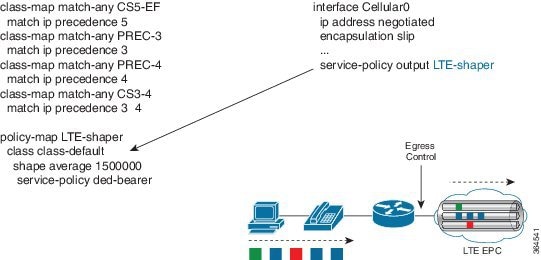
Quality of Service Configuration
The following figure is a diagrammatic representation of implementing QoS on 4G LTE network.
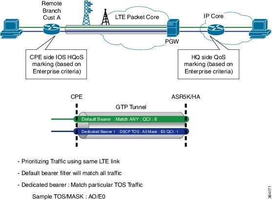
The following example shows a sample recommended configuration. In this example:
- Traffic from the end user is marked in ISRG2 routers; this enables the customer to map their traffic with the carrier-provided LTE QoS policy.
- Traffic from the end-user devices is marked in Ingress interfaces, and is policed in Egress interfaces. Policing in Egress interface can be done based on the carrier provided policy.
- The wide area cellular network is a shared medium and hence it is a variable bandwidth environment. By designing and implementing an effective traffic control policy at the Egress interface (cellular interface), radio resources can be efficiently utilized to support business critical applications. For the IOS QoS to work correctly, the onus is on the end user to determine the appropriate LTE bandwidth for traffic shaping purposes.
In this example, the carrier has provided the following LTE policy:
- 1 default bearer: Best effort
- 1 Non-GBR dedicated bearer: Allow DSCP CS4: Rate-limited to 500 Kbps
- 1 GBR dedicated bearer: Allow DSCP CS5: rate limited to 50 Kbps
- Overall average bandwidth is taken into account and the egress traffic is shaped to 1.5 Mbps
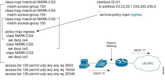
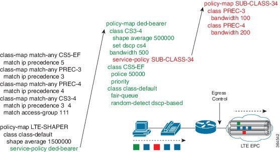
The following figure shows the Ingress Traffic Marking Policy configuration:
The following figure shows the Egress Class-Based Traffic Control Policy configuration:
For more information about configuring QoS features, see Quality of Service Solutions Configuration Guide Library, Cisco IOS Release 15M&T.
Troubleshooting QoS
The cellular interface notifies a user with a syslog message when QoS is enabled during the router boot-up, or when the modem attaches to the network. It also sends a message when a TFT profile is added, deleted, or modified by the core network. Users need to change the configuration on their side to match TFT profile. The following table lists the syslog messages generated for various events.
|
Syslog Message |
Description |
|---|---|
|
The dedicated bearer has been added. Check the TFT rules of the dedicated bearer by using the show cellular command, and add QoS configuration accordingly. |
|
There could be a network issue that needs further investigation. Contact your carrier. |
|
The host QoS configuration may need to be modified to match the modem configuration. Check the TFT rules of the bearer by using the show cellular command, and configure the host QoS configuration to match the TFT rules. |
|
The dedicated bearer configuration has been modified. Check the TFT rules of the bearer by using the show cellular command, and configure the host QoS configuration to match the TFT rules. |
Cellular Modem Link Recovery
The Cellular Modem Link Recovery feature is used to check whether the modem functions properly and bring back the modem to normal operation state if the modem is in inoperative state. When an inoperative state is identified, the modem is reset (the cellular modem is power cycled). Link recovery is enabled by default.
There are four configurable parameters to adjust the behavior of cellular link recovery. The default values have been optimized for the best performance of the feature and changing it is not recommended unless advised by Cisco.
The following table explains the cellular modem link recovery parameters.
|
Parameter |
Description |
|---|---|
|
rssi onset-threshold |
This parameter defines the RSSI value below which the link recovery feature triggers additional scrutiny to look for potential issues and take action if needed. The range of this parameter can be set from -90 dBm to -125 dBm. The recommended and default value is -110 dBm. |
|
monitor-timer |
This parameter determines how often link recovery looks for potential issues. The default value for this parameter is 20 seconds which means, link recovery feature will be triggered every 20 seconds and look at certain parameters to determine if there is a potential issue. You can configure the monitor-timer range between 20 to 60 seconds. Increasing the monitor timer value above 20 seconds will increase the response time of the feature. |
|
wait-timer and debounce-count |
The wait-timer parameter is used in conjunction with the debounce-count parameter to perform more frequent, additional checks, once the link recovery feature has identified a potential issue that needs to be recovered from, with a modem power-cycle. The default value for wait-timer is 10 seconds and the default value for debounce- count is 6. With this setting, once link recovery has identified an inoperative modem state, it performs additional checks every 10 seconds, up to 6 times, to determine if the issue has been resolved without a modem reset. Reducing the debounce-count and the wait-timer makes faster link recovery, while reducing them may increase the time for recovery. The configurable range for wait-timer is 5-60 seconds. The configurable range for debounce-count is 6-20 seconds. |
Cellular Modem Link Recovery Monitoring and Statistics
When the cellular modem link recovery occurs and modem is reset, you can see the %CELLWAN-2-MODEM_DOWN message on the console logs. Effective with Cisco IOS release 15.6(2.0c)T0, additionally there is a %CELLWAN-2-LINK_RECOVERY message which indicates that action has been taken by the cellular modem link recovery feature.
Whenever the cellular modem link recovery is occurred, it updates the Modem timeouts counter under the Modem Management Statistics section of the show controller cellular unit command output. Modem parameters at the last timeout section has information that helps to identify the cause of the issue that triggered link recovery
In the following example log, the messages, modem time out counter, and modem parameters at the last time out are highlighted.
*Jul 19 17:15:18.980 PDT: %CELLWAN-2-LINK_RECOVERY: Cellular0/1/0: Cellular Modem has been power cycled
Router# show controller cellular 0/1/0
Interface Cellular0/1/0
 LTE Adv WWAN NIM - Latin America Multimode LTE/DC-HSPA+/HSPA+/HSPA/UMTS/EDGE/GP unit 1 manufacture id:  0x00001199     product id: 0x00009071
 Sierra Wireless Direct IP EM7430 modem
 GPS Feature: enabled
 GPS Mode Configured: not configured
 GPS Status: NMEA Disabled
 Cellular Dual SIM details:
 ---------------------------
 SIM 0 is present
 SIM 1 is present
 SIM 0 is active SIM

  Module OIR Details
 -----------------------------------------------
  Module type : NIM-LTEA-LA
  Module Serial Number : FOC20084WGP
  Module Last Inserted on : Tue Jul 19 10:16:34 2016
 -----------------------------------------------
  Module Reload Statistics
 -------------------------
  Soft OIR reloads = 0
  Hard OIR reloads = 0
 -------------------------

 Modem Management Statistics
 ---------------------------
 Modem resets = 1
 Modem user initiated resets = 0
 Modem user initiated power-cycles = 0
 Modem timeouts = 1
 Modem parameters at the last timeout:
         LTE first time attach State was No
         Radio Interface Technology Mode was AUTO
         Operating Mode was Online
         RSSI was -0 dBm
         Packet switch domain status was Not Attached
         Registration state(EMM) was Not Registered
         Downlink traffic was not present
 Link recovery is ON
Registration check is ON
 RSSI threshold value is -110 dBm
 Monitor Timer value is 20 seconds
 Wait Timer value is 10 seconds
 Debounce Count value is 6
PLMN Search and Selection
Starting from Cisco IOS Release 15.5(3)M1, manual Public Land Mobile Network (PLMN) is supported on Cisco 8xx routers and EHWICs. This feature allows you to search for available PLMNs and connect to one of the PLMN.
Restrictions
The following restrictions apply for PLMN search and selection:
- Support in Cisco LTE 2.0 and MC73xx modem series and above.
- You have to verify whether your cellular service supports roaming or not.
- You have to use a SIM card that supports roaming.
- This feature is not supported on 4G+WiFi platforms.
- Supported firmware version is 5.5.58.x or later.
- Supported IOS release is Cisco IOS Release 15.5(3)M1 or later.
Commands
Use the following commands on fixed platforms:
- cellular x lte plmn search
- show cellular x network
- cellular x lte plmn select mode mcc mnc rat duration
Use the following commands on EHWICs:
- cellular x/x/x lte plmn search
- show cellular x/x/x network
- cellular x/x/x lte plmn select mode mcc mnc rat duration
Searching the Network
You can use the cellular 0 lte plmn search command to search for available PLMNs. The following example shows how to search for networks:
router#cellular 0 lte plmn search
Searching for available PLMNs.This may take up to 3 minutes.
Please wait...........................
PLMN search done. Please use "show cellular 0 network" to see available PLMNS
After the search, use the show cellular 0 network command to see the available networks:
router#show cellular 0 network
Current System Time = Fri Sep 18 18:49:24 2015
Current Service Status = Normal
Current Service = Packet switched
Current Roaming Status = Roaming
Network Selection Mode = Manual
Network = O2 - UK
Mobile Country Code (MCC) = 234
Mobile Network Code (MNC) = 10
Packet switch domain(PS) state = Attached
Location Area Code (LAC) = 4931
Cell ID = 34319
Available PLMNs:
Idx MCC MNC RAT     Desc
1   234 10  umts    O2 - UK
2   234 10  gsm     O2 - UK
3   234 20  umts    3 UK
4   234 30  umts    EE
5   234 15  gsm     voda UK
6   234 33  gsm     EE
7   234 20  lte     3 UK
8   234 30  gsm     EE
9   234 15  umts    voda UK
10  234 30  lte     EE
11  234 10  lte     O2 - UK
12  234 15  lte     voda UK
Selecting the Network
There are three ways to select an available network: Auto mode, Force Mode, and Manual mode. In Auto mode, the router will connect automatically to a network preferred by the SIM card. In Force mode, the router is forced to select an available or known network without performing a network search. If a network is not available or the router is unable to attach to a network, then the router will remain in a ‘Not attached’ state. You can use the cellular x lte plan select auto command to attach the router to a network preferred by the SIM. In Manual mode, you can select an available network from your search result.
The following example shows how to select a network manually:
router#cellular 0 lte plmn select manual ?
	0-999 Mobile Country Code (MCC)
router#cellular 0 lte plmn select manual 234 ?
	0-999 Mobile Network Code (MNC)
router#cellular 0 lte plmn select manual 234 10 ?
  gsm   GSM
  lte   LTE
  umts  UMTS
router#cellular 0 lte plmn select manual 234 10 gsm ?
The following example shows how to force a network selection:
router#cellular 0 lte plmn select force ?
	0-999 Mobile Country Code (MCC)
router#cellular 0 lte plmn select force 310 ?
	0-999 Mobile Network Code (MNC)
router#cellular 0 lte plmn select force 310 410 ?
	2-3 MNC Digits Ex 23 means 2 Digits, 023 Means 3 Digits
router#cellular 0 lte plmn select force 310 410 2 ?
  gsm   GSM
  lte   LTE
  umts  UMTS
router#cellular 0 lte plmn select force 310 410 2 l
router#cellular 0 lte plmn select force 310 410 2 lte ?
Verifying PLMN Selection
Use show cellular 0 network command to verify the PLMN selection:
router#show cellular 0 network
Current System Time = Fri Sep 18 18:53:25 2015
Current Service Status = Normal
Current Service = Packet switched
Current Roaming Status = Roaming
Network Selection Mode = Manual
Network = O2 - UK
Mobile Country Code (MCC) = 234
Mobile Network Code (MNC) = 10
Packet switch domain(PS) state = Attached
Location Area Code (LAC) = 4931
Cell ID = 34319
Available PLMNs:
Idx MCC MNC RAT     Desc
1   234 10  umts    O2 - UK
2   234 10  gsm     O2 - UK
3   234 20  umts    3 UK
4   234 30  umts    EE
5   234 15  gsm     voda UK
6   234 33  gsm     EE
7   234 20  lte     3 UK
8   234 30  gsm     EE
9   234 15  umts    voda UK
10  234 30  lte     EE
11  234 10  lte     O2 - UK
12  234 15  lte     voda UK
router#show cellular 0 radio
Radio power mode = ON
Channel Number = 122
Current Band = GSM 900 Extended
Current RSSI = -48 dBm
Current ECIO = -127 dBm
Radio Access Technology(RAT) Preference = GSM
Radio Access Technology(RAT) Selected = EDGE
Note |
Some networks may not allow the router to connect. In such cases, you have to choose a different network. |
Note |
Restart your modem if the router is not able to connect to any network. |
SNMP MIBs
The following Simple Management Network Protocol (SNMP) MIBs are supported on Cisco 4G LTE WWAN EHWICs, Cisco 819 Series 4G LTE ISRs and Cisco C880 Series 4G LTE ISRs and Cisco C890 Series 4G LTE Series ISRs:
- IF-MIB
- ENTITY-MIB
- CISCO-WAN-3G-MIB
For the CISCO-WAN-3G-MIB, the following tables and sub-tables are supported for 3G and LTE technologies:
- ciscoWan3gMIB(661)
- ciscoWan3gMIBNotifs(0)
- ciscoWan3gMIBObjects(1)
- c3gWanCommonTable(1)
- c3gWanGsm(3)
- c3gGsmIdentityTable(1)
- c3gGsmNetworkTable(2)
- c3gGsmPdpProfile(3)
- c3gGsmPdpProfileTable(1)
- c3gGsmPacketSessionTable(2)
- c3gGsmRadio(4)
- c3gGsmRadioTable(1)
- c3gGsmSecurity(5)
- c3gGsmSecurityTable(1)
You can download the MIBs from the Cisco MIB Locator at http://www.cisco.com/go/mibs.
How to Configure Cisco 4G LTE
Verifying Modem Signal Strength and Service Availability
For the EHWIC, the unit argument identifies the router slot, WIC slot, and port separated by slashes (0/0/0). For the Cisco 800 Series 4G LTE ISRs, the unit argument identifies slot “0” for all commands.
For 4G-LTE EHWICs, the numbering for slot 0, wic 0, and port 0 is 0/0/0 for all commands. For Cisco 800 Series 4G LTE fixed platforms, use slot “0” for all commands.
SUMMARY STEPS
- show cellular unit network
- show cellular unit radio
- show cellular unit profile
- show cellular unit security
- show cellular unit all
DETAILED STEPS
| Command or Action | Purpose | |||
|---|---|---|---|---|
| Step 1 |
show cellular unit network Example: |
Displays information about the carrier network, cell site, and available service. |
||
| Step 2 |
show cellular unit radio Example: |
Shows the radio signal strength.
|
||
| Step 3 |
show cellular unit profile Example: |
Shows information about the modem data profiles created. |
||
| Step 4 |
show cellular unit security Example: |
Shows the security information for the modem, such as SIM and modem lock status. |
||
| Step 5 |
show cellular unit all Example: |
Shows consolidated information about the modem, profiles created, radio signal strength, network security, and so on. |
Creating, Modifying, or Deleting Modem Data Profiles
SUMMARY STEPS
- cellular unit lte profile [ create | delete ] profile-number [ apn [ authentication [ username password [ bearer-type]]]]
DETAILED STEPS
| Command or Action | Purpose | ||
|---|---|---|---|
|
cellular unit lte profile [ create | delete ] profile-number [ apn [ authentication [ username password [ bearer-type]]]] Example: |
Creates, modifies, or deletes a modem data profile in the privileged EXEC mode.
|
Configuring a SIM for Data Calls
Locking and Unlocking a SIM Card Using a PIN Code
Perform this task to lock or unlock a SIM card given by your service provider.
The SIM card gets blocked if the wrong PIN is entered three consecutive times. Make sure you enter the correct PIN the SIM is configured with. If your SIM card gets blocked, contact your service provider for a PUK code. Using the PUK code, you can unblock the SIM card.
Note |
For the EHWIC, the unit argument identifies the router slot, WIC slot, and port separated by slashes (0/0/0). For the Cisco 800 Series 4G LTE ISRs, the unit argument identifies slot “0” for all commands. |
SUMMARY STEPS
- cellular unit lte sim {lock | unlock } pin
DETAILED STEPS
| Command or Action | Purpose |
|---|---|
|
cellular unit lte sim {lock | unlock } pin Example: |
Locks or unlocks the SIM card using a PIN code.
|
Changing the PIN Code
Perform this task to change the PIN code of a SIM.
Note |
For the EHWIC, the unit argument identifies the router slot, WIC slot, and port separated by slashes (0/0/0). For the Cisco 800 Series 4G LTE ISRs, the unit argument identifies slot “0” for all commands. |
SUMMARY STEPS
- cellular unit lte sim change-pin pin new-pin
DETAILED STEPS
| Command or Action | Purpose |
|---|---|
|
cellular unit lte sim change-pin pin new-pin Example: |
Changes the assigned PIN code. SIM should be in locked state when the PIN is being changed. |
Verifying the Security Information of a Modem
Perform this task to verify the security information of a modem.
Note |
For the EHWIC, the unit argument identifies the router slot, WIC slot, and port separated by slashes (0/0/0). For the Cisco 800 Series 4G LTE ISRs, the unit argument identifies slot “0” for all commands. |
SUMMARY STEPS
- show cellular unit security
DETAILED STEPS
| Command or Action | Purpose |
|---|---|
|
show cellular unit security Example: |
Shows the security information of the modem, including the SIM lock status. |
Configuring Automatic Authentication for a Locked SIM
An unencrypted PIN can be configured to activate the Card Holder Verification (CHV1) code that authenticates a modem.
The SIM card gets blocked if the wrong PIN is entered three consecutive times. Make sure you enter the correct PIN the SIM is configured with. If your SIM card gets blocked, contact your service provider for a PUK code.
Follow these procedures when using an unencrypted Level 0 PIN to configure CHV1. For instructions on how to configure CHV1 using an encrypted Level 7 PIN, see the Configuring an Encrypted PIN for a SIM.
A SIM should be locked for SIM authentication to work. To verify the SIM’s status, use the show cellular unit security command.
For the EHWIC, the unit argument identifies the router slot, WIC slot, and port separated by slashes (0/0/0). For the Cisco 800 Series 4G LTE ISRs, the unit argument identifies slot “0” for all commands.
SUMMARY STEPS
- configure terminal
- controller cellular unit
- Do one of the following: lte sim authenticate 0 pin lte sim authenticate 0 pin slot {0 | 1 }
DETAILED STEPS
| Command or Action | Purpose | |||
|---|---|---|---|---|
| Step 1 |
configure terminal Example: |
Enters global configuration mode. |
||
| Step 2 |
controller cellular unit Example: |
Enters the cellular controller configuration mode. |
||
| Step 3 |
Do one of the following: lte sim authenticate 0 pin lte sim authenticate 0 pin slot {0 | 1 } Example: |
Authenticates the SIM CHV1 code by using an unencrypted (0 ) keyword and PIN. This PIN is sent to the modem for authentication with each subsequent LTE connection. If authentication passes based on the configured PIN, the data call is allowed. If authentication fails, the modem does not initiate the data call.
|
Configuring an Encrypted PIN for a SIM
To configure an encrypted PIN, the scrambled value of the PIN must be obtained. To get the scrambled Level 7 PIN and to configure the SIM CHV1 code for verification using this encrypted PIN, enter the following commands in the EXEC mode.
When obtaining the encrypted PIN for a SIM, a username and password are created by configuring password encryption, defining the username and associated password, copying the resulting scrambled password, and using this scrambled password in the SIM authentication command. After the scrambled PIN has been obtained and used in SIM authentication, the username created can be deleted from the Cisco IOS configuration.
A SIM should be locked for SIM authentication to work. To verify the SIM’s status, use the show cellular unit security command.
For the EHWIC, the unit argument identifies the router slot, WIC slot, and port separated by slashes (0/0/0). For the Cisco 800 Series 4G LTE ISRs, the unit argument identifies slot “0” for all commands.
SUMMARY STEPS
- configure terminal
- service password-encryption
- username name privilege 0 password pin
- do show run | i name
- controller cellular unit
- Do one of the following:
- lte sim authenticate {0 | 7 } pin
- lte sim authenticate {0 | 7 } pin slot {0 | 1 }
- exit
- no username name
- no service password-encryption
DETAILED STEPS
| Command or Action | Purpose | |||
|---|---|---|---|---|
| Step 1 |
configure terminal Example: |
Enters global configuration mode. |
||
| Step 2 |
service password-encryption Example: |
Enables password encryption. |
||
| Step 3 |
username name privilege 0 password pin Example: |
Creates username and password.
|
||
| Step 4 |
do show run | i name Example: |
Shows the username configuration line with the encrypted level 7 PIN for the username created in Step 3 (user “SIM” in the example shown). Copy the scrambled password for use in Step 6 (as the PIN). |
||
| Step 5 |
controller cellular unit Example: |
Enters the cellular controller configuration mode. |
||
| Step 6 |
Do one of the following:
Example: |
Authenticates the SIM CHV1 code by using the encrypted keyword 7 and the scrambled PIN from Step 4. The PIN is sent to the modem for authentication with each subsequent LTE connection. If authentication passes based on the configured PIN, the data call is allowed. If authentication fails, the modem does not initiate the data call. For Cisco 4G LTE WWAN EHWICs, use the first command. For the Cisco 819(H)G-4G-G ISR that supports dual SIM feature, use the second command.
|
||
| Step 7 |
exit Example: |
(Optional) Exits the cellular controller configuration mode. |
||
| Step 8 |
no username name Example: |
(Optional) Removes the username and password created in Step 3. |
||
| Step 9 |
no service password-encryption Example: |
(Optional) Disables password encryption. |
Applying a Modem Profile in a SIM Configuration
SUMMARY STEPS
- configure terminal
- controller cellular unit
- Do one of the following:
- lte sim data-profile number
- attach-profile number lte sim profile number attach-profile number slot {0 | 1}
DETAILED STEPS
| Command or Action | Purpose | |||
|---|---|---|---|---|
| Step 1 |
configure terminal Example: |
Enters the global configuration mode. |
||
| Step 2 |
controller cellular unit Example: |
Enters the cellular controller configuration mode. |
||
| Step 3 |
Do one of the following:
Example:Example: |
(All MC77xx modems) Applies the configured profile number to the SIM and its slot number. The default (primary) slot is 0.
|
Configuring a Dual SIM
Note |
You can manually activate a SIM using the cellular 0 lte sim activate slot 0 or 1 command. |
SUMMARY STEPS
- configure terminal
- controller cellular unit
- lte sim primary slot
- lte sim max-retry number
- lte failovertimer timeout-period
- lte sim data-profile number attach-profile number slot {0 | 1}
DETAILED STEPS
| Command or Action | Purpose | |
|---|---|---|
| Step 1 |
configure terminal Example: |
Enters the global configuration mode. |
| Step 2 |
controller cellular unit Example: |
Enters the cellular controller configuration mode. |
| Step 3 |
lte sim primary slot Example: |
(Optional) Enters either slot number 0 or 1 of the primary SIM. |
| Step 4 |
lte sim max-retry number Example: |
(Optional) Specifies the maximum number of failover retries from 1 to 65535. The default value is 10. |
| Step 5 |
lte failovertimer timeout-period Example: |
(Optional) By default, the failover time period is 2 minutes before the primary SIM switches over to the secondary SIM if service becomes unavailable. Specify a failover timeout value between 1 and 7 minutes before a switchover occurs. |
| Step 6 |
lte sim data-profile number attach-profile number slot {0 | 1} Example:Example: |
Applies the configured profile number to the SIM and its slot number. The default (primary) slot is 0. You must also identify the primary and secondary SIM for the configured profile when two SIMs are presented. |
Data Call Setup
The following figure shows a typical data call setup.
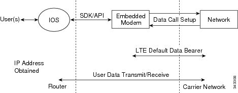
To set up a data call, use the following procedures:
Configuring the Cellular Interface
To configure the cellular interface, enter the following commands starting in EXEC mode.
Note |
For the EHWIC, the unit argument identifies the router slot, WIC slot, and port separated by slashes (0/0/0). For the Cisco 800 Series 4G LTE ISRs, the unit argument identifies slot “0” for all commands. |
Note |
Starting from Cisco IOS Release 15.3(3)M and 15.3(1)T, the chat-script configuration, including dialer in-band, dialer string, and script dialer, is auto-generated based on the modem type plugged in. The 3G and 4G EHWIC SKUs and the fixed 3G and 4G routers support these configuration changes. |
SUMMARY STEPS
- configure terminal
- interface cellular unit
- ip address negotiated
- encapsulation slip
- dialer in-band
- dialer string string
- dialer-group group-number
- exit
- chat-script script-name ”” “AT!CALL ” TIMEOUT timeout-value “OK ”
- ip route network-number network-mask {ip-address | interface } [administrative distance ] [name name ]
- dialer-list dialer-group protocol protocol-name {permit | deny | list access-list-number | access-group }
- line unit
- script dialer regular-expression
DETAILED STEPS
| Command or Action | Purpose | |||
|---|---|---|---|---|
| Step 1 |
configure terminal Example: |
Enters global configuration mode. |
||
| Step 2 |
interface cellular unit Example: |
Specifies the cellular interface. |
||
| Step 3 |
ip address negotiated Example: |
Specifies that the IP address for a particular interface is dynamically obtained. |
||
| Step 4 |
encapsulation slip Example: |
Specifies Serial Line Internet Protocol (SLIP) encapsulation for an interface configured for dedicated asynchronous mode or dial-on-demand routing (DDR). This is the default for asynchronous interfaces. |
||
| Step 5 |
dialer in-band Example: |
Enables DDR and configures the specified serial interface to use in-band dialing. |
||
| Step 6 |
dialer string string Example: |
Specifies the number or string to dial. |
||
| Step 7 |
dialer-group group-number Example: |
Specifies the number of the dialer access group to which the specific interface belongs. |
||
| Step 8 |
exit Example: |
Enters the global configuration mode. |
||
| Step 9 |
chat-script script-name ”” “AT!CALL ” TIMEOUT timeout-value “OK ” Example: |
Defines the ATDT commands when the dialer is initiated. |
||
| Step 10 |
ip route network-number network-mask {ip-address | interface } [administrative distance ] [name name ] Example: |
Establishes a floating static route with the configured administrative distance through the specified interface.
|
||
| Step 11 |
dialer-list dialer-group protocol protocol-name {permit | deny | list access-list-number | access-group } Example: |
Creates a dialer list for traffic of interest and permits access to an entire protocol. |
||
| Step 12 |
line unit Example: |
Specifies the line configuration mode. |
||
| Step 13 |
script dialer regular-expression Example: |
Specifies a default modem chat script. |
What to do next
Note |
If a tunnel interface is configured with ip unnumbered cellular 0/0/0 , it is necessary to configure the actual static IP address under the cellular interface, in place of ip address negotiated. |
Configuring DDR
To configure DDR for the cellular interface, enter the following commands starting in EXEC mode.
Note |
For the EHWIC, the unit argument identifies the router slot, WIC slot, and port separated by slashes (0/0/0). For the Cisco 800 Series 4G LTE ISRs, the unit argument identifies slot “0” for all commands. |
SUMMARY STEPS
- configure terminal
- interface cellular unit
- ip address negotiated
- encapsulation slip
- dialer in-band
- dialer pool-member number
- interface dialer number
- ip address negotiated
- encapsulation slip
- dialer pool number
- dialer idle-timeout seconds
- dialer string string
- dialer-group group-number
- exit
- dialer-list dialer-group protocol protocol-name {permit | deny | list access-list-number | access-group }
- access-list access-list-number permit ip-source-address
- line unit
- script dialer regular-expression
- exit
- chat-script script-name ”” “AT!CALL ” TIMEOUT timeout-value “OK ”
DETAILED STEPS
| Command or Action | Purpose | |
|---|---|---|
| Step 1 |
configure terminal Example: |
Enters global configuration mode. |
| Step 2 |
interface cellular unit Example: |
Specifies the cellular interface. |
| Step 3 |
ip address negotiated Example:Example: |
Specifies that the IP address for a particular interface is dynamically obtained. |
| Step 4 |
encapsulation slip Example: |
Specifies Serial Line Internet Protocol (SLIP) encapsulation for an interface configured for dedicated asynchronous mode or dial-on-demand routing (DDR). This is the default for asynchronous interfaces. |
| Step 5 |
dialer in-band Example: |
Enables DDR and configures the specified serial interface to use in-band dialing. |
| Step 6 |
dialer pool-member number Example: |
Specifies the number of a dialer profile’s dialing pool to which the specific interface belongs. |
| Step 7 |
interface dialer number Example: |
Specifies the number of a dialer rotary group to which the specific interface belongs. |
| Step 8 |
ip address negotiated Example: |
Specifies that the IP address for a particular interface is dynamically obtained. |
| Step 9 |
encapsulation slip Example: |
Specifies Serial Line Internet Protocol (SLIP) encapsulation for an interface configured for dedicated asynchronous mode or dial-on-demand routing (DDR). This is the default for asynchronous interfaces. |
| Step 10 |
dialer pool number Example: |
Specifies the number of a dialing pool that the dialer interface can use to connect to a specific destination subnetwork. |
| Step 11 |
dialer idle-timeout seconds Example: |
Specifies the duration of idle time, in seconds, after which a line will be disconnected. |
| Step 12 |
dialer string string Example: |
Specifies the number or string to dial. |
| Step 13 |
dialer-group group-number Example: |
Specifies the number of the dialer access group to which the specific interface belongs. |
| Step 14 |
exit Example: |
Enters the global configuration mode. |
| Step 15 |
dialer-list dialer-group protocol protocol-name {permit | deny | list access-list-number | access-group } Example: |
Creates a dialer list for traffic of interest and permits access to an entire protocol. |
| Step 16 |
access-list access-list-number permit ip-source-address Example: |
Defines traffic of interest. |
| Step 17 |
line unit Example: |
Specifies the line configuration mode. |
| Step 18 |
script dialer regular-expression Example: |
Specifies a default modem chat script. |
| Step 19 |
exit Example: |
Exits line configuration mode. |
| Step 20 |
chat-script script-name ”” “AT!CALL ” TIMEOUT timeout-value “OK ” Example: |
Defines the ATDT commands when the dialer is initiated. |
Configuring DDR Backup
To monitor the primary connection and initiate the backup connection when needed, the router can use one of the following methods:
-
Backup Interface—The backup interface that stays in standby mode until the primary interface line protocol is detected as down and then is brought up.
-
Floating Static Route—The route through the backup interface has an administrative distance that is greater than the administrative distance of the primary connection route and therefore would not be in the routing table until the primary interface goes down.
-
Dialer Watch—Dialer watch is a backup feature that integrates dial backup with routing capabilities.
Configuring Interfaces to Use a Backup Interface
Note |
You cannot configure a backup interface for the cellular interface and any other asynchronous serial interface. |
To configure one or more interfaces to use a backup interface, use the following commands, beginning in global configuration mode.
SUMMARY STEPS
- interface type number
- backup interface cellular number
- backup delay enable-delay-period disable-delay-period
DETAILED STEPS
| Command or Action | Purpose | |
|---|---|---|
| Step 1 |
interface type number Example: |
Specifies the interface to be backed up and begins interface configuration mode. |
| Step 2 |
backup interface cellular number Example: |
Specifies the cellular interface as backup. |
| Step 3 |
backup delay enable-delay-period disable-delay-period Example: |
Specifies delay between the physical interface going down and the backup interface being enabled and between the physical interface coming back up and the backup being disabled. |
Enabling 4G GPS and NMEA Data Streaming
GPS NMEA data streaming to external NMEA 2.0-compliant GPS plotter applications can be enabled on Cisco 4G LTE EHWICs, Cisco 819 Series 4G LTE ISRs, Cisco C880 Series 4G LTE ISRs, and Cisco C890 Series 4G LTE ISRs.
Note |
For an EHWIC, the unit argument identifies the router slot, WIC slot, and the port, and is separated by slashes (0/0/0). For the Cisco 800 Series 4G LTE ISRs, the unit argument identifies slot 0 for all commands. |
SUMMARY STEPS
- configure terminal
- controller cellular unit
- lte gps enable
- lte gps mode standalone
- Do one of the following:
- lte gps nmea {ip | serial [streaming]}
- lte gps nmea
- end
- show cellular unit gps
- show cellular unit gps detail
- show running config
- show line
- telnet ip address port
DETAILED STEPS
| Step 1 |
configure terminal Example:Enters the configuration mode. |
||
| Step 2 |
controller cellular unit Example:Enters the controller cellular configuration mode. |
||
| Step 3 |
lte gps enable Example:(Optional) GPS is enabled by default. Use this command to enable the GPS feature if GPS has been disabled for any reason. |
||
| Step 4 |
lte gps mode standalone Example:Enables the standalone GPS mode. |
||
| Step 5 |
Do one of the following:
Example:Enables NMEA streaming. Cisco 4G LTE EHWICs support only IP NMEA streaming. Therefore, IP interface and serial interface options are unavailable. Cisco 819 4G LTE ISRs, Cisco C880 Series 4G LTE ISRs, and Cisco C890 Series 4G LTE ISRs support the following NMEA streaming options:
|
||
| Step 6 |
end Example:Exits the controller configuration mode and returns to the privileged EXEC mode. |
||
| Step 7 |
show cellular unit gps Example:Displays a summary of the following GPS data:
|
||
| Step 8 |
show cellular unit gps detail Example:Displays detailed GPS data. |
||
| Step 9 |
show running config Example:Shows the output of the configuration. |
||
| Step 10 |
show line Example:Shows the async port number. After NMEA is configured, Cisco IOS creates a n NMEA async port. The port number is platform dependent. In this example, the async port number is line 6. |
||
| Step 11 |
telnet ip address port Example:After NMEA streaming is enabled, the modem starts to stream NMEA data over the NMEA port regardless of whether the GPS fix is acquired or not. You can reverse Telnet to the NMEA port to check the NMEA data. |
Configuring 4G SMS Messaging
Note |
In the context of an EHWIC, the unit argument identifies the router slot, WIC slot, and the port, and is separated by slashes (0/0/0). For the Cisco 1110 Series 4G LTE routers, the unit argument identifies slot 0 for all commands. |
SUMMARY STEPS
- configure terminal
- controller cellular unit
- lte sms archive path FTP-URL
- cellular unit lte sms view {all | ID | summary }
- end
- show cellular unit sms
- cellular unit lte sms send number
- cellular unit lte sms delete [all | id]
DETAILED STEPS
| Step 1 |
configure terminal Example:Enters the configuration mode. |
||
| Step 2 |
controller cellular unit Example:Enters the controller cellular configuration mode. |
||
| Step 3 |
lte sms archive path FTP-URL Example:Specifies an FTP server folder path to send all the incoming and outgoing SMS messages.
|
||
| Step 4 |
cellular unit lte sms view {all | ID | summary } Example:Displays the message contents of incoming texts received by a modem.
|
||
| Step 5 |
end Example:Exits the configuration mode and returns to the privileged EXEC mode. |
||
| Step 6 |
show cellular unit sms Example:Displays all the information in the text messages sent and received. Message information includes text messages sent successfully, received, archived, and messages pending to be sent. LTE-specific information on errors in case of a FAILED attempt may also be displayed. |
||
| Step 7 |
cellular unit lte sms send number Example:Enables a user to send a 4G LTE band SMS message to other valid recipients, provided they have a text message plan. The number argument is the telephone number of the SMS message recipient.
|
||
| Step 8 |
cellular unit lte sms delete [all | id] Example:(Optional) Deletes one message ID or all of the stored messages from memory. |
Configuring Cellular Modem Link Recovery
The cellular modem link recovery feature is enabled by default and it is recommended to enable the link recovery feature. Perform the following steps to disable or enable cellular modem link recovery if required.
SUMMARY STEPS
- configure terminal
- controller cellular unit
- Do one of the following:
- lte modem link-recovery disable
- no lte modem link-recovery link-recovery disable
- end
DETAILED STEPS
| Command or Action | Purpose | |
|---|---|---|
| Step 1 |
configure terminal Example: |
Enters the configuration mode. |
| Step 2 |
controller cellular unit Example: |
Enters the controller cellular configuration mode. |
| Step 3 |
Do one of the following:
Example:Example: |
Disables or enables the cellular modem link recovery feature. |
| Step 4 |
end Example: |
Exits the configuration mode and returns to the privileged EXEC mode. |
Verifying the Cellular Modem Link Recovery Configuration
To determine if the cellular modem link recovery is enabled, use the show controller cellular unit command. In this example, the cellular modem link recovery feature related information is highlighted.
Device# show controller cellular 0/1/0
Interface Cellular0/1/0
 4G WWAN EHWIC - Global Multimode(Australia) LTE/DC-HSPA+/HSPA+/HSPA/UMTS/EDGE/G unit 0
 EHWIC Cellular Modem Configuration
 ====================================
 Modem is recognized as valid for this EHWIC
 manufacture id:  0x00001199     product id: 0x000068C0
 Sierra Wireless Direct IP MC7304 modem
 GPS Feature: disabled
 GPS Status: GPS mode or nmea not enabled
 GPS Port selected: Dedicated GPS port

 Modem Management Statistics
 ---------------------------
 Modem resets = 2
 Modem user initiated resets = 0
 Modem user initiated power-cycles = 1
 Modem timeouts = 0
 Link recovery is ON
 Registration check is ON
 RSSI threshold value is -110 dBm
 Monitor Timer value is 20 seconds
 Wait Timer value is 10 seconds
 Debounce Count value is 6
Upgrading the Modem Firmware for MC77XX Modem
The following table describes the Sierra Wireless modems that are supported on Cisco 4G LTE EHWICs and Cisco 1110 Series routers. The firmware for the modem is upgradable using Cisco IOS commands. The firmware is a Crossword Express (cwe) file and can be downloaded from the wireless software download page on Cisco.com.
Note |
The firmware upgrade procedure explained here is applicable only to MC77xx modems. The procedure for MC73xx modem is explained here: http://www.cisco.com/c/en/us/td/docs/routers/access/interfaces/firmware/Firmware_Upgrade.html |
|
SKU |
Modem |
Firmware |
Release |
|---|---|---|---|
|
EHWIC-4G-LTE-A <SKU name for Cisco 1110> <SKU name for Cisco 1110> |
MC7700 |
3.5.29.02 |
Cisco 16.5.1 or Later |
Use only Cisco certified firmware. Using a firmware version not certified by Cisco may impact the wireless service provider network adversely.
Note |
Do not disconnect power or switch the router off during the firmware upgrade process. This may result in permanent modem failure. |
Note |
Firmware downgrade is not supported. |
Note |
The 3.5.x firmware must have a 15.2(4)M3 or later software image. |
Upgrading the Modem Firmware Manually for MC77XX Modem
Downloading the Firmware
Cisco recommends the manual upgrade process for the LTE modem firmware and IOS software image for all new deployments and the following existing deployments:
- LTE is not the primary ISR WAN interface.
- LTE is not the only ISR WAN interface.
- The network administrator has out-of-band or local access to the ISR.
You can also remotely download firmware by using the following steps.
SUMMARY STEPS
- Go to Cisco web page http://software.cisco.com/download/navigator.html and select firmware for Cisco 4G to download the latest certified firmware for your carrier.
- On this page, navigate as follows: Products -> Cisco Interfaces and Modules -> Cisco High-Speed WAN Interface Cards
- Select your product in the third column and download the appropriate LTE firmware to the flash memory on the router.
- Enable the logging console.
- Initiate the firmware upgrade process.
- Verify the upgrade process.
- Reload the ISR to complete the upgrade process.
DETAILED STEPS
| Step 1 |
Go to Cisco web page http://software.cisco.com/download/navigator.html and select firmware for Cisco 4G to download the latest certified firmware for your carrier.
|
||
| Step 2 |
On this page, navigate as follows: Products -> Cisco Interfaces and Modules -> Cisco High-Speed WAN Interface Cards A list of available cards displays in the third column as shown in the following figure. Select your product in the third column and download the appropriate LTE firmware. After clicking on the Cisco High-Speed WAN interface Cards selection, a list of available cards displays in the third column as shown in the following figure (). 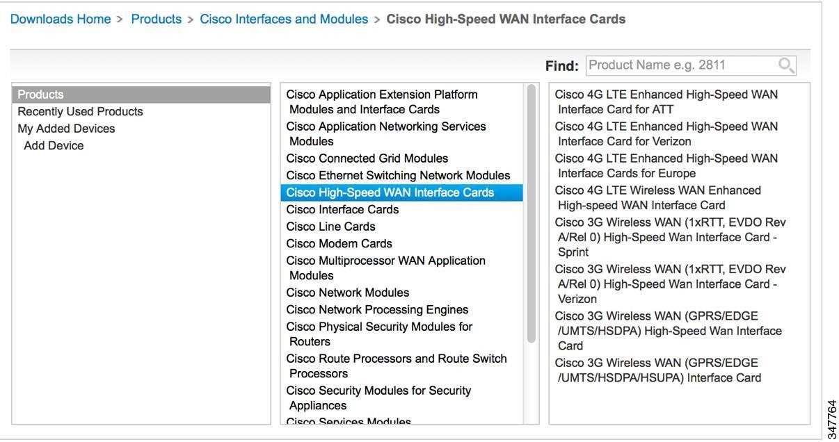 |
||
| Step 3 |
Select your product in the third column and download the appropriate LTE firmware to the flash memory on the router. |
||
| Step 4 |
Enable the logging console. |
||
| Step 5 |
Initiate the firmware upgrade process.
|
||
| Step 6 |
Verify the upgrade process. |
||
| Step 7 |
Reload the ISR to complete the upgrade process. |
Upgrading the Firmware on the Router
SUMMARY STEPS
- terminal monitor
- microcode reload cellular pa-bay slot modem-provision flash : filename
- show cellular unit show cellular 0 hardware
- reload
DETAILED STEPS
| Command or Action | Purpose | |||
|---|---|---|---|---|
| Step 1 |
terminal monitor Example: |
Enables the logging console in privileged EXEC mode. |
||
| Step 2 |
microcode reload cellular pa-bay slot modem-provision flash : filename Example:Example:Example: |
Initiates the firmware upgrade process.
|
||
| Step 3 |
show cellular unit show cellular 0 hardware Example:Example:Example: |
Verifies the firmware upgrade process. The first command pertains to Cisco 4G LTE EHWIC and the second command pertains to Cisco 819 Series 4G LTE ISRs, Cisco C880 Series 4G LTE ISRs, and Cisco C890 Series 4G LTE ISRs. |
||
| Step 4 |
reload |
Reloads the IOS application software image to complete the firmware upgrade.
|
Upgrading the Modem Firmware Using the EEM Scripts
For existing field deployments where LTE is the only WAN interface, and there is no local or out-of-band administrative access to the router, an automated upgrade method using a Cisco IOS Embedded Event Manager (EEM) script is recommended. The EEM script upgrades the modem firmware and reloads the router with the IOS software image that is compatible with the new firmware release.
Downloading the Modem Firmware and Installing the EEM Scripts
SUMMARY STEPS
- Go to the Cisco Wireless WAN software download website at: http://software.cisco.com/download/navigator.html.
- On this page, select from the following options:Products -> Cisco Interfaces and Modules -> Cisco High-Speed WAN Interface Cards
- Download the selected LTE firmware release.
- no boot system flash: filename
- terminal monitor
- configure terminal
- Copy EEM Script 1 and EEM Script 2 for your modem (see the following this section) and paste this text into the router's running configuration.
- show event manager policy registered
DETAILED STEPS
| Command or Action | Purpose | |||
|---|---|---|---|---|
| Step 1 |
Go to the Cisco Wireless WAN software download website at: http://software.cisco.com/download/navigator.html. |
Provides access to Cisco Wireless WAN software downloads. Select firmware for Cisco 4G.
|
||
| Step 2 |
On this page, select from the following options:Products -> Cisco Interfaces and Modules -> Cisco High-Speed WAN Interface Cards |
After the Cisco High-Speed WAN interface Cards is selected, a list of available cards displays in the third column. Select your product in the third column and download the appropriate LTE firmware. |
||
| Step 3 |
Download the selected LTE firmware release. |
Download the modem firmware file to flash memory on the router. |
||
| Step 4 |
no boot system flash: filename Example: |
Deletes any boot system flash: commands from the running configuration in global configuration mode. |
||
| Step 5 |
terminal monitor Example: |
Enables the logging console in privileged EXEC mode. |
||
| Step 6 |
configure terminal Example: |
Enters global configuration mode. |
||
| Step 7 |
Copy EEM Script 1 and EEM Script 2 for your modem (see the following this section) and paste this text into the router's running configuration. |
Installs the EEM scripts on the router.
with: |
||
| Step 8 |
show event manager policy registered Example: |
Verifies that the policy is registered.
|
Running the EEM Scripts on the Router to Upgrade the Modem
SUMMARY STEPS
- event manager run fw slot-number
- show cellular slot hardware
DETAILED STEPS
| Command or Action | Purpose | |||
|---|---|---|---|---|
| Step 1 |
event manager run fw slot-number Example: |
Identifies the EHWIC-4G-LTE slot number.
|
||
| Step 2 |
show cellular slot hardware Example:Example:Example: |
Verifies that the upgrade was successful. If the upgrade was successful, a message similar to the one shown in the example should appear. |
Removing EEM Scripts from the Router once the Modem Upgrades Successfully
SUMMARY STEPS
- configure terminal
- no event manager applet applet-name
- end
- write memory
DETAILED STEPS
| Command or Action | Purpose | |
|---|---|---|
| Step 1 |
configure terminal Example: |
Enters global configuration mode. |
| Step 2 |
no event manager applet applet-name Example:Example: |
Deregisters the applet with the Embedded Event Manager (EEM) and enters applet configuration mode for this applet. |
| Step 3 |
end Example: |
Exits global configuration mode and enters privileged EXEC mode. |
| Step 4 |
write memory Example:Example: |
Saves the running configuration to NVRAM on the ISR. |
Upgrading the Modem Firmware Manually for MC7430 Modem
For MC74XX modems and the later versions, firmware will be provided as three separate files. The three files are firmware file with .cwe extension, carrier provisioning file (PRI) with .nvu extension, and Cisco (OEM) PRI file with .nvu extension. The supported Cisco IOS software for this firmware upgrade procedure is <release number?> and later versions.
Three types of firmware upgrades are possible depending on the requirements.
- Upgrading firmware file and carrier PRI file.
- Upgrading only the carrier provisioning file used to switch from one carrier to other.
- Upgrading only the Cisco OEM PRI file which is used to upgrade from the old Cisco OEM PRI file to the new Cisco OEM PRI file.
You should download only the required files for each firmware upgrade procedure. As part of the firmware upgrade, you need to create a directory in the router flash. The directory should contain only the required files for the specific firmware upgrade procedure. For example, if you are upgrading only the carrier provisioning file, the directory should only contain the carrier provisioning file.
Note |
You should always execute the firmware upgrade command from flash. If you execute the firmware upgrade command inside a directory or folder the firmware upgrade may fail. |
Note |
You should reload the router after the modem firmware upgrade. |
Note |
When you create a directory in the flash for firmware upgrade, you shouldn’t create any subdirectories under the directory. |
Upgrading Firmware File and Carrier PRI file
Perform the following steps to manually upgrade the firmware file and carrier PRI file for MC7430 modem.
SUMMARY STEPS
- Go to the Cisco web page http://software.cisco.com/download/navigator.html to download the latest certified firmware for your carrier which can be found under the path: Products -> Cisco Interfaces and Modules -> LTE Wireless WAN Interfaces
- Download the firmware files to the router flash over Ethernet or cellular or any other WAN interface. This can be done by hosting the firmware files on a FTP or TFTP server and reaching to that server via any WAN interface on the router.
- Create a directory in the flash.
- Copy the firmware files to the created directory in the flash. Before you copy the firmware, make sure that the files are available in a TFTP server.
- Ensure that the firmware file (CWE) and carrier PRI file (NVU) have the same version and both files are available under the same directory.
- Initiate the firmware upgrade process using the microcode reload cellular command. When you use this command, provide the directory name instead of firmware file name.
- Once the firmware upgrade begins, wait for a few minutes. The firmware upgrade may take upto 7 minutes. The following message will be displayed if the firmware upgrade is successful.
- Once the message indicates a successful upgrade, wait for 2 minutes till modem comes up.
- After the firmware upgrade, reload the router and verify that you have the latest firmware.
- After the firmware upgrade as well as after the router reload, the modem status should be online. Check whether the modem status is online.
DETAILED STEPS
| Step 1 |
Go to the Cisco web page http://software.cisco.com/download/navigator.html to download the latest certified firmware for your carrier which can be found under the path: Products -> Cisco Interfaces and Modules -> LTE Wireless WAN Interfaces |
||
| Step 2 |
Download the firmware files to the router flash over Ethernet or cellular or any other WAN interface. This can be done by hosting the firmware files on a FTP or TFTP server and reaching to that server via any WAN interface on the router. |
||
| Step 3 |
Create a directory in the flash. Example: |
||
| Step 4 |
Copy the firmware files to the created directory in the flash. Before you copy the firmware, make sure that the files are available in a TFTP server. Example: |
||
| Step 5 |
Ensure that the firmware file (CWE) and carrier PRI file (NVU) have the same version and both files are available under the same directory. Example:
|
||
| Step 6 |
Initiate the firmware upgrade process using the microcode reload cellular command. When you use this command, provide the directory name instead of firmware file name. For EHWIC-LTE-LA, EHWIC-LTE-JN, and EHWIC-LTE-CI Example:For C819GW-LTE-LA-CK9, C819GW-LTE-LA-QK9, C819GW-LTE-LA-NK9 Example: |
||
| Step 7 |
Once the firmware upgrade begins, wait for a few minutes. The firmware upgrade may take upto 7 minutes. The following message will be displayed if the firmware upgrade is successful. For EHWIC-LTE-LA, EHWIC-LTE-JN, EHWIC-LTE-CI, C898EAG-LTE-LA-K9, and C897VAG-LTE-LA-K9, C899G-LTE-LA-K9, C819G-LTE-LA-K9 Example:For C819GW-LTE-LA-CK9, C819GW-LTE-LA-QK9, C819GW-LTE-LA-NK9 Example: |
||
| Step 8 |
Once the message indicates a successful upgrade, wait for 2 minutes till modem comes up. |
||
| Step 9 |
After the firmware upgrade, reload the router and verify that you have the latest firmware. Example:
|
||
| Step 10 |
After the firmware upgrade as well as after the router reload, the modem status should be online. Check whether the modem status is online. Example: |
Upgrading only the Carrier Provisioning File
Perform the following steps to manually upgrade the carrier PRI file for MC7430 modem.
SUMMARY STEPS
- Perform the steps from 1 to 4 in Upgrading Firmware File and Carrier PRI file.
- Ensure that the currently running firmware version in the modem has the same version as the carrier PRI file going to be upgraded.
- Initiate the firmware upgrade process using the microcode reload cellular command. When you use this command, provide the directory name instead of firmware file name.
- Once the firmware upgrade begins, wait for a few minutes. The firmware upgrade may take upto 7 minutes. The following message will be displayed if the firmware upgrade is successful.
- Once the message indicates a successful upgrade, wait for 2 minutes till the modem comes up.
- After the firmware upgrade, reload the router to verify that you have the latest firmware.
- After the firmware upgrade, as well as after the modem reload, the modem status should be online. Check whether the modem status is online.
DETAILED STEPS
| Step 1 |
Perform the steps from 1 to 4 in Upgrading Firmware File and Carrier PRI file. |
||
| Step 2 |
Ensure that the currently running firmware version in the modem has the same version as the carrier PRI file going to be upgraded. Example: |
||
| Step 3 |
Initiate the firmware upgrade process using the microcode reload cellular command. When you use this command, provide the directory name instead of firmware file name. For EHWIC-LTE-LA, EHWIC-LTE-JN, and EHWIC-LTE-CI Example:For C819GW-LTE-LA-CK9, C819GW-LTE-LA-QK9, C819GW-LTE-LA-NK9 Example: |
||
| Step 4 |
Once the firmware upgrade begins, wait for a few minutes. The firmware upgrade may take upto 7 minutes. The following message will be displayed if the firmware upgrade is successful. For EHWIC-LTE-LA, EHWIC-LTE-JN, EHWIC-LTE-CI, C898EAG-LTE-LA-K9, C897VAG-LTE-LA-K9, C899G-LTE-LA-K9 and C819G-LTE-LA-K9 Example:For C819GW-LTE-LA-CK9, C819GW-LTE-LA-QK9, C819GW-LTE-LA-NK9 Example: |
||
| Step 5 |
Once the message indicates a successful upgrade, wait for 2 minutes till the modem comes up. |
||
| Step 6 |
After the firmware upgrade, reload the router to verify that you have the latest firmware. Example:
|
||
| Step 7 |
After the firmware upgrade, as well as after the modem reload, the modem status should be online. Check whether the modem status is online. Example: |
Upgrading only the Cisco OEM PRI File
Perform the following steps to manually upgrade the Cisco OEM PRI file for MC7430 modem.
SUMMARY STEPS
- Perform the steps from 1 to 4 in Upgrading Firmware File and Carrier PRI file.
- Check the versions of old OEM PRI and the new OEM PRI and ensure that the old PRI is available. Use the show cell slot hardware command to check the OEM PRI version.
- Initiate the firmware upgrade process using the microcode reload cellular command. When you use this command, provide the directory name instead of firmware file name.
- Once the firmware upgrade begins, wait for a few minutes. The firmware upgrade may take upto 7 minutes. The following message will be displayed if the firmware upgrade is successful.
- Once the message indicates a successful upgrade, wait for 2 minutes till the modem comes up.
- After the firmware upgrade, reload the router and verify that you have the latest firmware.
- After the firmware upgrade, as well as after the reload, the modem status should be online. Check whether the modem status is online.
DETAILED STEPS
| Step 1 |
Perform the steps from 1 to 4 in Upgrading Firmware File and Carrier PRI file. |
||
| Step 2 |
Check the versions of old OEM PRI and the new OEM PRI and ensure that the old PRI is available. Use the show cell slot hardware command to check the OEM PRI version. Example: |
||
| Step 3 |
Initiate the firmware upgrade process using the microcode reload cellular command. When you use this command, provide the directory name instead of firmware file name. For EHWIC-LTE-LA, EHWIC-LTE-JN, and EHWIC-LTE-CI Example:For C819GW-LTE-LA-CK9, C819GW-LTE-LA-QK9, C819GW-LTE-LA-NK9 Example: |
||
| Step 4 |
Once the firmware upgrade begins, wait for a few minutes. The firmware upgrade may take upto 7 minutes. The following message will be displayed if the firmware upgrade is successful. For EHWIC-LTE-LA, EHWIC-LTE-JN, EHWIC-LTE-CI, C898EAG-LTE-LA-K9, C897VAG-LTE-LA-K9, C899G-LTE-LA-K9, and C819G-LTE-LA-K9 Example:For C819GW-LTE-LA-CK9, C819GW-LTE-LA-QK9, C819GW-LTE-LA-NK9 Example: |
||
| Step 5 |
Once the message indicates a successful upgrade, wait for 2 minutes till the modem comes up. |
||
| Step 6 |
After the firmware upgrade, reload the router and verify that you have the latest firmware. Example:
|
||
| Step 7 |
After the firmware upgrade, as well as after the reload, the modem status should be online. Check whether the modem status is online. Example: |
Cisco Network PnP Discovery Over 4G Interface
Cisco Network Plug and Play (PnP) over 4G interface is available on platforms that have 4G NIMs and running Cisco IOS Release 15.7M&T or later releases. When you boot a device with an activated SIM card, the 4G interface is activated and used for the Cisco Network PnP cloud discovery process. When you boot a device without an activated SIM card, the non-4G interfaces are preferred for the discovery process. Cisco Network PnP cloud discovery over 4G interfaces is attempted when the non-4G interfaces are not available or if the Cisco Network PnP discovery does not succeed on the non-4G interfaces. When the device has multiple 4G interfaces with active SIM cards, the Cisco Network PnP will try the cloud discovery on all the 4G interfaces one after the other until one of them succeeds.
By default, Cisco Network PnP Cloud discovery over 4G interfaces works when all the 4G interfaces are activated during the device bootup. In the absence of a startup configuration, the device attempts to bring up the 4G interface by default and attempts Cisco PnP over cloud. After the device is redirected, the device connects to the Cisco Network PnP server and downloads the appropriate image and configuration to the device.
Note |
PnP Discovery over 4G Interface supports only IPv4. |
Note |
Image upgrade on Cisco IR800 and Cisco CGR1000 is not supported. Only configuration upgrade is supported. |
Note |
Ensure that the configuration pushed through the Cisco Network PnP server contains a route to the Cisco Network PnP server over the 4G interface. This route can be a default route and should retain the Cisco Network PnP agent and server communication to continue to work over the 4G interface, after the provisioning is completed. |
Prerequisites for Cisco Network PnP Discovery Over 4G Interface
-
4G NIMs have an activated SIM card inserted in it.
-
The modem has the correct firmware. If the firmware on the modem is generic, you have to configure the Access Point Name (APN) manually.
-
Antennas are properly installed and radio signal is good.
-
You have to program the PnP Connect (the cloud redirect server) to its appropriate server. Using your smart account credentials, you can do it at software.cisco.com portal. For more information on how to do it, see https://www.youtube.com/watch?v=EOTK6Sb5gRQ&list=PLGqSRuvZkXDcw0lCR-vBPNIos05kMsagu&index=4
How PnP over 4G LTE Works
The following workflow shows how PnP works over 4G LTE:
|
Steps |
Process |
|---|---|
|
Step 1 |
4G modem attaches to the base station and obtains a DHCP IP address. |
|
Step 2 |
DHCP allocates an IP address to the cellular interface. After that, the PnP discovery process starts. |
|
Step 3 |
The router connects to Cisco Plug and Play Connect portal at devicehelper.cisco.com over a secure HTTPS channel. The portal redirects the device to its appropriate PnP Server or Controller. |
|
Step 4 |
The APIC-EM server securely provisions the configuration and image. |
The following figure illustrates the workflow:
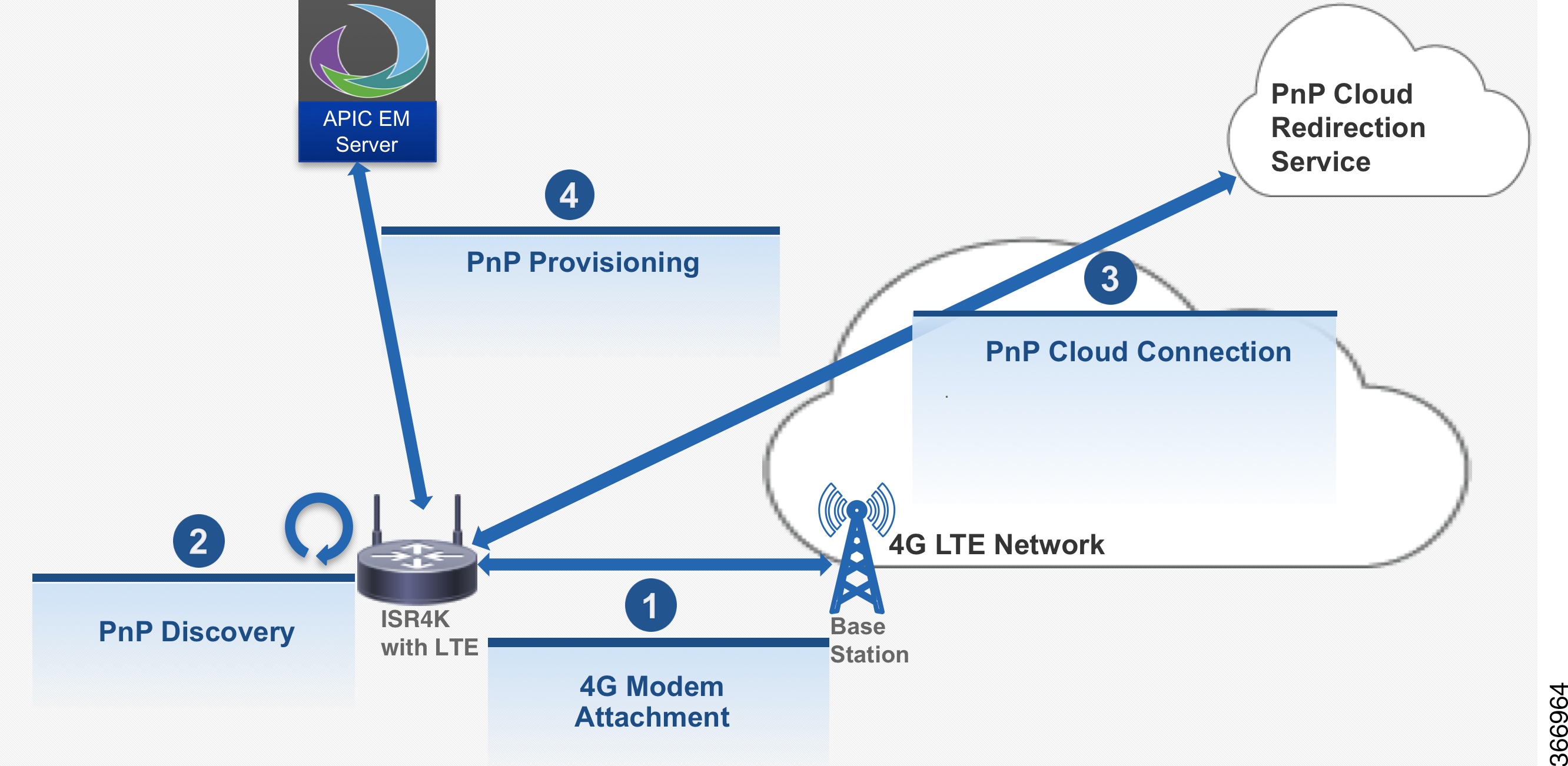
Troubleshooting
You do not need to manually enable PnP. PnP is enabled automatically when the router boots up.
Note |
PnP is not invoked if the startup configuration is present in the router. |
The following log file shows a successful scenario of the PnP boot-up:
*May 22 17:34:45.011: %PNP-6-PNP_4G_DISCOVERY_STARTING: PnP Discovery over 4G Starting..Please Wait

*May 22 17:49:15.638: %PNP-6-HTTP_CONNECTING: PnP Discovery trying to connect to PnP server https://72.163.11.184/pnp/HELLO

May 22 17:49:22.917: %PNP-6-HTTP_CONNECTED: PnP Discovery connected to PnP server https://72.163.11.184/pnp/HELLO

May 22 17:53:34.556: %PNP-6-PNP_DISCOVERY_DONE: PnP Discovery done successfully
The following log file shows a failure scenario when the startup configuration is present in the router:
*Jun 14 20:51:04.037: %PNP-6-PNP_DISCOVERY_STOPPED: PnP Discovery stopped (Startup Config Present)
The following log file shows a failure scenario when a user interrupts the PnP discovery process:
*Jun 14 21:23:16.059: %PNP-6-PNP_DISCOVERY_STOPPED: PnP Discovery stopped (Config Wizard)
Enabling Serviceability
Serviceability or Non-Access Stratum (NAS) is a set of protocols in the Evolved Packet System. The NAS is used to convey non-radio signaling between the User Equipment (UE) and the Mobility Management Entity (MME). The serviceability feature collects the NAS messages during a network outage and helps you to narrow down the issues on the network or UE side.
Restrictions
Follow these restrictions and usage guideline while configuring serviceability .
-
This feature is not supported on the C819GW router and 4G CGM module.
Enabling Serviceability
The following example shows how to enable serviceability:
Router#config terminal
Router(config)#controller cellular 0/0/0
Router(config-controller)#lte modem svb-log enable
Router(config-controller)#end
The following example shows how to specify the log size and the file size of the log file:
Router#config terminal
Router(config)#controller cellular 0/0/0
Router(config-controller)#lte modem svb-log size 0
Router(config-controller)#lte modem svb-log filesize 1
Router(config-controller)#lte modem svb-log enable
Router(config-controller)#end
Viewing Log File
Use the show cellular slot logs svb-log command to display the log file.
Router#show cellular 0/0/0 logs svb-log
Modem SVB logging is on
output path = flash:
maximum log size = none
maximum file size = 1048576
log rotation = disabled

70 packets received from the modem, 12746 bytes, 0 input drops
70 packets stored in file system, 12746 bytes, 0 errors, 0 aborts
6 max rcv queue size

current file size = 43244
current log size = 43244
total log size = 43244
SVB log files: (14 files)
        flash:svblog20170712-205107slot128.bin size 8504
        flash:svblog20170720-223315slot128.bin size 196
        flash:svblog20170720-223542slot128.bin size 196
        flash:svblog20170720-224009slot128.bin size 196
        flash:svblog20170720-224157slot128.bin size 688
        flash:svblog20170720-224915slot128.bin size 196
        flash:svblog20170720-225110slot128.bin size 688
        flash:svblog20170720-230316slot128.bin size 196
        flash:svblog20170720-231407slot128.bin size 196
        flash:svblog20170721-171844slot128.bin size 196
        flash:svblog20170721-172034slot128.bin size 688
        flash:svblog20170721-172534slot128.bin size 492
        flash:svblog20170721-205042slot128.bin size 13078
        flash:svblog20170727-211335slot128.bin size 17734
Router#
Router#dir flash:svb*
Directory of bootflash:/svb*

Directory of bootflash:/

40970  -rw-         196  Jul 20 2017 22:33:15 +00:00  svblog20170720-223315slot128.bin
40975  -rw-         196  Jul 20 2017 22:35:42 +00:00  svblog20170720-223542slot128.bin
40978  -rw-         196  Jul 20 2017 22:40:09 +00:00  svblog20170720-224009slot128.bin
40979  -rw-         688  Jul 20 2017 22:46:48 +00:00  svblog20170720-224157slot128.bin
40980  -rw-         196  Jul 20 2017 22:49:18 +00:00  svblog20170720-224915slot128.bin
40981  -rw-         688  Jul 20 2017 22:53:45 +00:00  svblog20170720-225110slot128.bin
40982  -rw-         196  Jul 20 2017 23:03:16 +00:00  svblog20170720-230316slot128.bin
40983  -rw-         196  Jul 20 2017 23:14:07 +00:00  svblog20170720-231407slot128.bin
40984  -rw-         196  Jul 21 2017 17:18:44 +00:00  svblog20170721-171844slot128.bin
40985  -rw-         688  Jul 21 2017 17:23:46 +00:00  svblog20170721-172034slot128.bin
40986  -rw-         492  Jul 21 2017 17:25:34 +00:00  svblog20170721-172534slot128.bin
40987  -rw-       13078  Jul 27 2017 12:15:15 +00:00  svblog20170721-205042slot128.bin
40988  -rw-       17734   Aug 2 2017 00:10:15 +00:00  svblog20170727-211335slot128.bin
7169642496 bytes total (76120064 bytes free)
Router#
Configuring and Verifying Maximum Transmission Unit
This section explains how to configure the Maximum Transmission Unit (MTU) on a cellular interface.
Note |
You can set a MTU of 2K on the cellular interface if your service provider's network can support it. |
Prerequisites for Configuring MTU
-
The network of the Service Provider support Maximum Transmission Unit (MTU) of 2K.
-
Before you configure the feature, you have to upgrade the OEM PRI file of the modem.
Restrictions
Follow these restrictions and usage guideline while configuring MTU.
-
This feature (MTU of 2K) is supported only on the EM7455, MC7304, and MC7354MNA modems.
Configuring MTU
The supported MTU value is determined only after a call is established between the modem and the network. The cellular interface can accept an MTU value up to 2000 bytes.
The following example shows how to set the MTU value to 2000:
Router#config terminal
Router(config)#interface cellular 0/0/0
Router(config-if)#mtu 2000
Router(config-if)#end
Verifying MTU Configuration
Use the show cellular slot network command to verify the MTU configuration. Note that the MTU value is available only after a call is established between the modem and the network.
The following example shows the output of the command before a call:
Router#show cellular 1 network
Current System Time = Sun Jan 6 0:1:39 1980
Current Service Status = Normal
Current Service = Packet switched
Current Roaming Status = Roaming
Network Selection Mode = Automatic
Network = 123 456
Mobile Country Code (MCC) = 123
Mobile Network Code (MNC) = 456
Packet switch domain(PS) state = Attached
LTE Carrier Aggregation state = Deconfigured
Registration state(EMM) = Registered
EMM Sub State = Normal Service
Tracking Area Code (TAC) = 1
Cell ID = 256
Network MTU is not Available
Router#
The following example shows the output of the command after a call:
Note |
For 73XX modems, the below output always shows negotiated network MTU value as 2000. |
Router#show cellular 1 network
Current System Time = Sun Jan 6 0:1:2 1980
Current Service Status = Normal
Current Service = Packet switched
Current Roaming Status = Roaming
Network Selection Mode = Automatic
Network = Test1-1
Mobile Country Code (MCC) = 1
Mobile Network Code (MNC) = 1
Packet switch domain(PS) state = Attached
LTE Carrier Aggregation state = Deconfigured
Registration state(EMM) = Registered
EMM Sub State = Normal Service
Tracking Area Code (TAC) = 1
Cell ID = 256
Negotiated network MTU is 2000
Router#
Troubleshooting
This section provides the necessary background information and resources available for troubleshooting the Cisco 4G-LTE Wireless WAN EHWIC.
For LED descriptions, see Cisco 4G LTE Wireless WAN EHWIC .
Verifying Data Call Setup
To verify the data call setup, follow these steps:
- After you create a modem data profile using the cellular profile create command and configuring DDR on the cellular interface, send a ping from the router to a host across the wireless network.
- If the ping fails, debug the failure by using the following debug and show commands:
- debug chat
- debug modem
- debug dialer
- show cellular all
- show interface cellular
- show running-config
- show ip route
- Save the output from these commands and contact your system administrator.
Checking Signal Strength
If the Received Signal Strength Indication (RSSI) level is very low (for example, if it is less than –110 dBm), follow these steps:
SUMMARY STEPS
- Check the antenna connection. Make sure the TNC connector is correctly threaded and tightened.
- If you are using a remote antenna, move the antenna cradle and check if the RSSI has improved.
- Contact your wireless service provider to verify if there is service availability in your area.
DETAILED STEPS
| Step 1 |
Check the antenna connection. Make sure the TNC connector is correctly threaded and tightened. |
| Step 2 |
If you are using a remote antenna, move the antenna cradle and check if the RSSI has improved. |
| Step 3 |
Contact your wireless service provider to verify if there is service availability in your area. |
Verifying Service Availability
The following is a sample output for the show cellular all command for a scenario where the antenna is disconnected and a modem data profile has not been created. The errors in this case have been highlighted with >>>>>>> .
Device# show cellular 0/0/0 all
Hardware Information
====================
Modem Firmware Version = SWI9600M_01.00.09.03
Modem Firmware built = 2011/07/01 19:31:09
Hardware Version = 20460000
International Mobile Subscriber Identity (IMSI) = <specific sim number>
International Mobile Equipment Identity (IMEI) = <specific modem number>
Electronic Serial Number (ESN) = <specific ESN in Hex> [specific ESN in Dec]
Integrated Circuit Card ID (ICCID) = <specific ICCID number>
Mobile Subscriber International Subscriber
IDentity Number (MSISDN) = <specific phone number>
Profile Information
====================
 * - Default profile
>>>>>>>>

no profile here.
Data Connection Information
===========================
Profile 1, Packet Session Status = INACTIVE
        Inactivity Reason = Normal inactivate state
Profile 2, Packet Session Status = INACTIVE
        Inactivity Reason = Normal inactivate state
Profile 3, Packet Session Status = INACTIVE
        Inactivity Reason = Normal inactivate state
Profile 4, Packet Session Status = INACTIVE
        Inactivity Reason = Normal inactivate state
Profile 5, Packet Session Status = INACTIVE
        Inactivity Reason = Normal inactivate state
Profile 6, Packet Session Status = INACTIVE
        Inactivity Reason = Normal inactivate state
Profile 7, Packet Session Status = INACTIVE
        Inactivity Reason = Normal inactivate state
Profile 8, Packet Session Status = INACTIVE
        Inactivity Reason = Normal inactivate state
Profile 9, Packet Session Status = INACTIVE
        Inactivity Reason = Normal inactivate state
Profile 10, Packet Session Status = INACTIVE
        Inactivity Reason = Normal inactivate state
Profile 11, Packet Session Status = INACTIVE
        Inactivity Reason = Normal inactivate state
Profile 12, Packet Session Status = INACTIVE
        Inactivity Reason = Normal inactivate state
Profile 13, Packet Session Status = INACTIVE
        Inactivity Reason = Normal inactivate state
Profile 14, Packet Session Status = INACTIVE
        Inactivity Reason = Normal inactivate state
Profile 15, Packet Session Status = INACTIVE
        Inactivity Reason = Normal inactivate state
Profile 16, Packet Session Status = INACTIVE
        Inactivity Reason = Normal inactivate state

Network Information
===================
Current Service Status = No service, Service Error = None
>>>>>>> no service means not connected to the network.
Current Service = Packet Switched
Current Roaming Status = Home
Network Selection Mode = Automatic
Country = , Network =
Mobile Country Code (MCC) = 0
Mobile Network Code (MNC) = 0
Radio Information
=================
Radio power mode = Online
Current RSSI = -125 dBm
>>>>>>> either no antenna, or bad antenna or out of network.
Radio power mode = Online
LTE Technology Selected = LTE
Modem Security Information
==========================
Card Holder Verification (CHV1) = Disabled
SIM Status = OK
SIM User Operation Required = None
Number of CHV1 Retries remaining = 3
Successful Call Setup
The following is a sample output when a call is set up using a chat script. It shows a received IP address from the network. Call setup is successful and data path is open.
debugs
debug modem
debup chat
Device#
Aug 25 18:46:59.604: CHAT0/0/0: Attempting async line dialer script
Aug 25 18:46:59.604: CHAT0/0/0: Dialing using Modem script: lte & System script: none
Aug 25 18:46:59.604: CHAT0/0/0: process started
Aug 25 18:46:59.604: CHAT0/0/0: Asserting DTR
Aug 25 18:46:59.604: CHAT0/0/0: Chat script lte started
Aug 25 18:46:59.604: CHAT0/0/0: Sending string: AT!CALL
Aug 25 18:46:59.604: CHAT0/0/0: Expecting string: OK
Aug 25 18:47:00.641: CHAT0/0/0: Completed match for expect: OK
Aug 25 18:47:00.641: CHAT0/0/0: Chat script lte finished, status = Success
Aug 25 18:47:00.641: TTY0/0/0: no timer type 1 to destroy
Aug 25 18:47:00.641: TTY0/0/0: no timer type 0 to destroy
Aug 25 18:47:00.641: TTY0/0/0: no timer type 2 to destroy
Aug 25 18:47:02.642: %LINK-3-UPDOWN: Interface Cellular0/0/0, changed state to up
Aug 25 18:47:02.642: %DIALER-6-BIND: Interface Ce0/0/0 bound to profile Di1
Aug 25 18:47:03.642: %LINEPROTO-5-UPDOWN: Line protocol on Interface Cellular0/0/0, changed state to up (69.78.96.14) [OK]
Modem Troubleshooting Using Integrated Modem DM Logging
As part of the 3G and 4G serviceability enhancement in Cisco IOS Release 15.2(4)M2 and Cisco IOS Release 15.3(1)T, DM log collection has been integrated into Cisco IOS, eliminating the need for an external PC and simplifying the DM log collection process. The lte modem dm-log command can be used in controller cellular configuration mode to configure integrated DM logging to monitor traffic on the modem. See the Cisco 3G and 4G Serviceability Enhancement User Guide for more information on configuring Integrated DM Logging parameters.
Modem Settings for North America and Carriers Operating on 700 MHz Band
For HWIC-3G deployments in North America and for carriers operating in the 700 MHz band, the following changes to the modem settings are required to prevent long network attach times.
The output of show cellular x/x/x all command shows the following:
- Current RSSI is –125 dBM
- LTE Technology Preference = No preference specified (AUTO)
Changing Modem Settings
To change the modem settings to force the modem to scan different technologies, use the following Cisco IOS command:
Device# cellular 0/0/0 lte technology
auto         Automatic LTE Technology Selection
cdma-1xrtt   CDMA 1xRTT
cdma-evdo    CDMA EVDO Rev A
cdma-hybrid  HYBRID CDMA
gsm          GSM
lte          LTE
umts         UMTS
Electronic Serial Number (ESN)
The ESN number is located directly on the modem label in hexadecimal notation. It can also be retrieved using the Cisco IOS CLI using the show cellular slot/port/hwic hardware command.
The sample output below shows the ESN number:
Hardware Information
====================
Electronic Serial Number (ESN) = 0x603c9854 [09603971156]
Electronic Serial Number (ESN) = <specific ESN in hexadecimal> [specific ESN in decimal]
Configuration Examples for 4G LTE
Example: Basic Cellular Interface Configuration: Cisco EHWIC-4G-LTE
The following example shows how to configure the cellular interface to be used as a primary and is configured as the default route:
Device# show running-config
chat-script lte "" "AT!CALL" TIMEOUT 20 "OK"
interface Cellular0/0/0
ip address negotiated
encapsulation slip
dialer in-band
dialer string lte
dialer-group 1
async mode interactive
ip route 172.22.1.10 255.255.255.255 cellular 0/0/0
dialer-list 1 protocol ip permit
line 0/0/0
script dialer lte
modem InOut
Example: Basic Cellular Interface Configuration: Cisco 819 4G LTE ISR
The following example shows how to configure the cellular interface to be used as primary and is configured as the default route:
chat-script lte "" "AT!CALL1" TIMEOUT 20 "OK"
!
!
controller Cellular 0
!
!
interface Cellular0
 ip address negotiated
 encapsulation slip
 load-interval 30
 dialer in-band
 dialer idle-timeout 0
 dialer string lte
 dialer-group 1
 no peer default ip address
 async mode interactive
 routing dynamic
!
ip route 172.22.1.10 255.255.255.255 cellular 0/0/0
!
dialer-list 1 protocol ip permit
!
line 3
 script dialer lte
 modem InOut
 no exec
 transport input all
 transport output all
!
Example: Creating, Modifying, or Deleting Modem Data Profiles
The following example shows how to change a default profile on EHWIC-4G-LTE-A:
router(config-controller)# lte sim data-profile 2 attach-profile 1
router(config-controller)# end
router#
router# sh run
Building configuration...
controller Cellular 0/1
 lte sim profile 2
router# ping 8.8.4.4 rep 10
Type escape sequence to abort.
Sending 10, 100-byte ICMP Echos to 8.8.4.4, timeout is 2 seconds:
!!!!!!!!!!
Success rate is 100 percent (10/10), round-trip min/avg/max = 284/364/600 ms
router#
The following example shows the output of the show cellular command:
router# show cellular 0/1/0 profile
Profile 1 = INACTIVE **
--------
PDP Type = IPv4
Access Point Name (APN) = Broadband
Profile 2 = ACTIVE*
--------
PDP Type = IPv4
PDP address = 10.176.207.8
Access Point Name (APN) = Broadband
        Primary DNS address = 172.26.38.1
        Secondary DNS address = 172.26.38.2
  * - Default profile
 ** - LTE attach profile
The following example shows the output of the show cellular command before you enable the debug command:
router# show cellular 0/0/0 profile
Profile 1 = INACTIVE **
--------
PDP Type = IPv6
Access Point Name (APN) = vzwims
Profile 2 = INACTIVE
--------
PDP Type = IPv4v6
Access Point Name (APN) = vzwadmin
Profile 3 = ACTIVE*
--------
PDP Type = IPv4v6
PDP address = 10.187.130.3
Access Point Name (APN) = VZWINTERNET
        Primary DNS address = 198.224.173.135
        Secondary DNS address = 198.224.174.135
Profile 4 = INACTIVE
--------
PDP Type = IPv4v6
Access Point Name (APN) = vzwapp

  * - Default profile    /* Note
 ** - LTE attach profile  /* note
The following example shows the output of the show cellular command after you enable the debug command:
router# debug cellular 0/0/0 messages profile
PROFILE_3GPP2 debugging is on
router#
router #show cellular 0/0/0 profile
Profile 1 = INACTIVE **
--------
PDP Type = IPv6
Access Point Name (APN) = vzwims
Profile 2 = INACTIVE
--------
PDP Type = IPv4v6
Access Point Name (APN) = vzwadmin
Profile 3 = ACTIVE*
--------
PDP Type = IPv4v6
PDP address = 10.187.130.3
Access Point Name (APN) = VZWINTERNET
        Primary DNS address = 198.224.173.135
        Secondary DNS address = 198.224.174.135
Profile 4 = INACTIVE
--------
PDP Type = IPv4v6
Access Point Name (APN) = vzwapp
3GPP2 Profiles:
==============
Profile 1 = INACTIVE
--------
PDN Type = IPv6
Access Point Name (APN) = vzwims
Profile 2 = INACTIVE
--------
PDN Type = IPv4v6
Access Point Name (APN) = vzwadmin
Profile 3 = INACTIVE*
--------
PDN Type = IPv4v6
Access Point Name (APN) = VZWINTERNET
Profile 4 = INACTIVE
--------
PDN Type = IPv4v6
Access Point Name (APN) = vzwapp

Profile 5 = INACTIVE
--------
PDN Type = IPv4v6
Access Point Name (APN) =
Profile 6 = INACTIVE
--------
PDN Type = IPv4v6
Access Point Name (APN) =
  * - Default profile
 ** - LTE attach profile
Example: Configuring a Dual SIM
The following example shows how to configure a dual SIM:
router# configure terminal
router(config)# controller Cellular 0
router(config-controller)# lte sim
data-profile
1 attach-profile
 1 slot 0
router(config-controller)# lte sim
data-profile
2 attach-profile
 2 slot 1
router(config-controller)# lte sim primary slot 1
router(config-controller)# lte sim max-retry 20
router(config-controller)# lte sim failovertimer 5
The following example shows how to display an active profile on a SIM:
router# show cellular 0 profile
Profile Information
====================
Profile 1 = INACTIVE
--------
PDP Type = IPv4
Access Point Name (APN) = internet.telenor.se
Profile 2 = ACTIVE* **
--------
PDP Type = IPv4
PDP address = 78.78.16.214
Access Point Name (APN) = telia.online.se
        Primary DNS address = 195.67.199.18
        Secondary DNS address = 195.67.199.19
  * - Default profile
 ** - LTE attach profile
Configured default profile for active SIM 1 is profile 2.
The following example shows how to display the status of a dual SIM:
router# show cellular 0 security
Active SIM = 0
SIM switchover attempts = 0
Card Holder Verification (CHV1) = Disabled
SIM Status = OK
SIM User Operation Required = None
Number of CHV1 Retries remaining = 3
router#
The following example shows how to display the status of a dual SIM:
router# show controller cellular 0
Interface Cellular0
4G WWAN Modem - Global Multimode LTE/DC-HSPA+/HSPA+/HSPA/UMTS/EDGE/GPRS
Cellular modem configuration
======================================
Modem is recognized as valid
manufacture id:  0x00001199     product id: 0x000068A2
Power status: Active
Sierra Wireless Direct IP MC7710 modem
:
:
Cellular Dual SIM details:
---------------------------
SIM 0 is present
SIM 1 is present
SIM 0 is active SIM
Cellular Interface Configuration for Always-On Connection
Dialer-Watch Configuration without External Dialer Interface
The following example shows how to configure dialer-watch without external dialer interface. The bold text is used to indicate important commands that are specific to dialer-watch.
chat-script lte "" "AT!CALL" TIMEOUT 20 "OK"
interface Cellular0/0/0
 ip address negotiated
 encapsulation slip
 dialer in-band
 dialer string LTE
 dialer watch-group 1
 async mode interactive
!
dialer watch-list 1 ip 5.6.7.8 0.0.0.0
dialer watch-list 1 delay route-check initial 60
dialer watch-list 1 delay connect 1
!
ip route 0.0.0.0 0.0.0.0 cellular 0/0/0
line 0/0/0
 script dialer LTE
 modem InOut
 no exec
 transport input all
 transport output all
Dialer-Persistent Configuration with External Dialer Interface
The following example shows how to configure dialer-persistent with external dialer interface. The bold text is used to indicate important commands that are specific to dialer-persistent.
chat-script lte "" "AT!CALL" TIMEOUT 20 "OK"
interface Cellular0/0/0
 ip address negotiated
  encapsulation slip
 dialer in-band
 dialer pool-member 1
 async mode interactive
 routing dynamic
interface Dialer1
ip address negotiated
encapsulation slip
 dialer pool 1
 dialer idle-timeout 0
 dialer string lte
 dialer persistent
 dialer-group 1
!
dialer-list 1 protocol ip permit
ip route 0.0.0.0 0.0.0.0 dialer 1
line 0/0/0
 script dialer lte
 modem InOut
 no exec
 transport input all
 transport output all
Example: GRE Tunnel over Cellular Interface Configuration
The following example shows how to configure the static IP address when a GRE tunnel interface is configured with ip address unnumbered cellular interface :
Note |
The GRE tunnel configuration is supported only if the service providers provide a public IP address on the LTE interface. |
Note |
For service providers using a private IP address, the point-to-point static GRE tunnel cannot be set up with a private IP address at one end and a public IP address on the other end. |
interface Tunnel2
ip unnumbered **internal LAN interface GE0/0 etc.**
tunnel source Cellular0
tunnel destination a.b.c.d
interface Cellular0
ip address negotiated
encapsulation slip
no ip mroute-cache
dialer in-band
dialer string lte
dialer-group 1
async mode interactive
4G-LTE Wireless WAN as Backup with NAT and IPSec
The following example shows how to configure the 4G-LTE wireless WAN on the router as backup with NAT and IPSec:
Note |
The receive and transmit speeds cannot be configured. The actual throughput depends on the cellular network service. |
ip dhcp excluded-address 10.4.0.254
!
ip dhcp pool lan-pool
   network 10.4.0.0 255.255.0.0
   dns-server 10.4.0.254
   default-router 10.4.0.254
!
!
chat-script lte "" "AT!CALL" TIMEOUT 20 "OK"
crypto isakmp policy 1
 encr 3des
 authentication pre-share
crypto isakmp key  address a.b.c.d
!
!
crypto ipsec transform-set  ah-sha-hmac esp-3des
!
crypto map gsm1 10 ipsec-isakmp
 set peer a.b.c.d
 set transform-set
 match address 103
!
!
interface ATM0/0/0
 no ip address
 ip virtual-reassembly
 load-interval 30
 no atm ilmi-keepalive
 dsl operating-mode auto
!
interface ATM0/0/0.1 point-to-point
 backup interface Cellular0/3/0
 ip nat outside
 ip virtual-reassembly
 no snmp trap link-status
 pvc 0/35
  pppoe-client dial-pool-number 2
 !
!
interface Cellular0/3/0
 ip address negotiated
 ip nat outside
 ip virtual-reassembly
 encapsulation slip
 no ip mroute-cache
 dialer in-band
 dialer idle-timeout 0
 dialer string lte
 dialer-group 1
 async mode interactive
 crypto map gsm1
!
interface Vlan104
 description used as default gateway address for DHCP clients
 ip address 10.4.0.254 255.255.0.0
 ip nat inside
 ip virtual-reassembly
!
interface Dialer2
 ip address negotiated
 ip mtu 1492
 ip nat outside
 ip virtual-reassembly
 encapsulation ppp
 load-interval 30
 dialer pool 2
 dialer-group 2
 ppp authentication chap callin
 ppp chap hostname cisco@dsl.com
 ppp chap password 0 cisco
 ppp ipcp dns request
 crypto map gsm1
!
ip local policy route-map track-primary-if
ip route 0.0.0.0 0.0.0.0 Dialer2 track 234
ip route 0.0.0.0 0.0.0.0 Cellular0/3/0 254
!
!
ip nat inside source route-map nat2cell interface Cellular0/3/0 overload
ip nat inside source route-map nat2dsl interface Dialer2 overload
!
ip sla 1
 icmp-echo 2.2.2.2 source-interface Dialer2
 timeout 1000
 frequency 2
ip sla schedule 1 life forever start-time now
access-list 1 permit any
access-list 101 deny ip 10.4.0.0 0.0.255.255 10.0.0.0 0.255.255.255
access-list 101 permit ip 10.4.0.0 0.0.255.255 any
access-list 102 permit icmp any host 2.2.2.2
access-list 103 permit ip 10.4.0.0 0.0.255.255 10.0.0.0 0.255.255.255
dialer-list 1 protocol ip list 1
dialer-list 2 protocol ip permit
!
!
route-map track-primary-if permit 10
 match ip address 102
 set interface Dialer2
!
route-map nat2dsl permit 10
 match ip address 101
 match interface Dialer2
!
route-map nat2cell permit 10
 match ip address 101
 match interface Cellular0/3/0
!
line 0/3/0
 exec-timeout 0 0
 script dialer lte
 login
 modem InOut
Note |
For service providers using a private IP address, use the crypto ipsec transform-set esp command (that is, esp-aes esp-sha256-hmac...). |
SIM Configuration: Examples
Locking the SIM Card: Example
The following example shows how to lock the SIM. The italicized text in this configuration example is used to indicate comments and are not be seen when a normal console output is viewed.
Device# sh cellular 0/0/0 security
Card Holder Verification (CHV1) = Disabled
SIM Status = OK
SIM User Operation Required = None
Number of CHV1 Retries remaining = 3
Device#! !	SIM is in unlocked state. ! Device# cellular 0/0/0 lte sim lock 1111
!!!WARNING: SIM will be locked with pin=1111(4).
Do not enter new PIN to lock SIM. Enter PIN that the SIM is configured with.
Call will be disconnected!!!
Are you sure you want to proceed?[confirm]
Device#
Apr 26 19:35:28.339: %CELLWAN-2-MODEM_DOWN: Modem in HWIC slot 0/0 is DOWN
Apr 26 19:35:59.967: %CELLWAN-2-MODEM_UP: Modem in HWIC slot 0/0 is now UP
Device#
Device# sh cellular 0/0/0 security
Card Holder Verification (CHV1) = Enabled
SIM Status = Locked
SIM User Operation Required = Enter CHV1
Number of CHV1 Retries remaining = 3
Device#! !	SIM is in locked state. !
Unlocking the SIM Card: Example
The following example shows how to unlock the SIM. The italicized text throughout this configuration example is used to indicate comments and will not be seen when a normal console output is viewed.
Device# sh cellular 0/0/0 security
Card Holder Verification (CHV1) = Enabled
SIM Status = Locked
SIM User Operation Required = Enter CHV1
Number of CHV1 Retries remaining = 3
Device#! !	SIM is in locked state. ! Device# cellular 0/0/0 lte sim unlock 1111
!!!WARNING: SIM will be unlocked with pin=1111(4).
Do not enter new PIN to unlock SIM. Enter PIN that the SIM is configured with.
Call will be disconnected!!!
Are you sure you want to proceed?[confirm]
Device#
Device# sh cellular 0/0/0 security
Card Holder Verification (CHV1) = Disabled
SIM Status = OK
SIM User Operation Required = None
Number of CHV1 Retries remaining = 3
Device#! !	SIM is in unlocked state. !
Automatic SIM Authentication: Example
The following example shows how to configure automatic SIM authentication. The italicized text throughout this configuration example is used to indicate comments and will not be seen when a normal console output is viewed.
Device# show cellular 0/0/0 security
Card Holder Verification (CHV1) = Disabled
SIM Status = OK
SIM User Operation Required = None
Number of CHV1 Retries remaining = 3
Device#! !	SIM is in unlocked state. ! Device# cellular 0/0/0 lte sim lock 1111
!!!WARNING: SIM will be locked with pin=1111(4).
Do not enter new PIN to lock SIM. Enter PIN that the SIM is configured with.
Call will be disconnected!!!
Are you sure you want to proceed?[confirm]
Device#
Apr 26 21:22:34.555: %CELLWAN-2-MODEM_DOWN: Modem in HWIC slot 0/0 is DOWN
Apr 26 21:23:06.495: %CELLWAN-2-MODEM_UP: Modem in HWIC slot 0/0 is now UP
Device#
Device# sh cellular 0/0/0 security
Card Holder Verification (CHV1) = Enabled
SIM Status = Locked
SIM User Operation Required = Enter CHV1
Number of CHV1 Retries remaining = 3
Device#! !	SIM is in locked state. SIM needs to be in locked state for SIM authentication to  !	work. ! Device#
Device# conf term
Enter configuration commands, one per line.  End with CNTL/Z.
Device(config)# controller cellular 0/0
Device(config-controller)# lte sim authenticate 0 1111
CHV1 configured and sent to modem for verification
Device(config-controller)# end
Device#
Apr 26 21:23:50.571: %SYS-5-CONFIG_I: Configured from console by console
Device#
Device# sh cellular 0/0/0 security
Card Holder Verification (CHV1) = Enabled
SIM Status = OK
SIM User Operation Required = None
Number of CHV1 Retries remaining = 3
Device#! !	SIM is now in locked state but it can be used for connectivity since authentication is  !	good. Authentication can be saved in the router configuration so that when you boot up  !	the router with the same locked SIM, connection can be established with the correct  !	Cisco IOS configuration. !
Changing the PIN Code: Example
The following example shows how to change the assigned PIN code. The italicized text throughout this configuration example is used to indicate comments and will not be seen when a normal console output is viewed.
Device# sh cellular 0/0/0 security
Card Holder Verification (CHV1) = Disabled
SIM Status = OK
SIM User Operation Required = None
Number of CHV1 Retries remaining = 3
Device#! !	SIM is in unlocked state. ! Device#
Device# cellular 0/0/0 lte sim lock 1111
!!!WARNING: SIM will be locked with pin=1111(4).
Do not enter new PIN to lock SIM. Enter PIN that the SIM is configured with.
Call will be disconnected!!!
Are you sure you want to proceed?[confirm]
Device#
Apr 26 21:58:11.903: %CELLWAN-2-MODEM_DOWN: Modem in HWIC slot 0/0 is DOWN
Apr 26 21:58:43.775: %CELLWAN-2-MODEM_UP: Modem in HWIC slot 0/0 is now UP
Device#
Device# sh cellular 0/0/0 security
Card Holder Verification (CHV1) = Enabled
SIM Status = Locked
SIM User Operation Required = Enter CHV1
Number of CHV1 Retries remaining = 3
Device#! !	SIM is in locked state. SIM needs to be in locked state to change its PIN. ! Device#
Device# cellular 0/0/0 lte sim change-pin 1111 0000
!!!WARNING: SIM PIN will be changed from:1111(4) to:0000(4)
Call will be disconnected. If old PIN is entered incorrectly in 3 attempt(s), SIM will be blocked!!!
Are you sure you want to proceed?[confirm]
Resetting modem, please wait...
CHV1 code change has been completed. Please enter the new PIN in controller configuration for verfication
Device#
Apr 26 21:59:16.735: %CELLWAN-2-MODEM_DOWN: Modem in HWIC slot 0/0 is DOWN
Apr 26 21:59:48.387: %CELLWAN-2-MODEM_UP: Modem in HWIC slot 0/0 is now UP
Device#
Device#
Device# sh cellular 0/0/0 security
Card Holder Verification (CHV1) = Enabled
SIM Status = Locked
SIM User Operation Required = Enter CHV1
Number of CHV1 Retries remaining = 3
Device#! !	SIM stays in locked state, as expected, but with new PIN. ! Device# cellular 0/0/0 lte sim unlock 0000
!!!WARNING: SIM will be unlocked with pin=0000(4).
Do not enter new PIN to unlock SIM. Enter PIN that the SIM is configured with.
Call will be disconnected!!!
Are you sure you want to proceed?[confirm]
Device#
Device# show cellular 0/0/0 security
Card Holder Verification (CHV1) = Disabled
SIM Status = OK
SIM User Operation Required = None
Number of CHV1 Retries remaining = 3
Device#! !	Unlock with new PIN is successful. Hence, changing PIN was successful. !
Configuring an Encrypted PIN: Example
The following example shows how to configure automatic SIM authentication using an encrypted PIN. The italicized text throughout this configuration example is used to indicate comments and will not be seen when a normal console output is viewed.
Device# configure terminal
Enter configuration commands, one per line.  End with CNTL/Z.
Device(config)# service password-encryption
Device(config)# username SIM privilege 0 password 1111
Device(config)# do sh run | i SIM
username SIM privilege 0 password 7 055A575E70.! !	Copy the encrypted level 7 PIN. Use this scrambled PIN in the SIM authentication  !	command. ! Device(config)#
Device(config)# controller cellular 0/0
Device(config-controller)# lte sim authenticate 7 055A575E70
CHV1 configured and sent to modem for verification
Device(config-controller)# exit
Device(config)# no username SIM
Device(config)# end
May 14 20:20:52.603: %SYS-5-CONFIG_I: Configured from console by console
SMS Initiated Call Back Configuration: Example
The following example shows how to configure SMS initiated data callback feature on a dialer interface to set up a data connection by sending a text message to the modem and securing the data connection by using the originating (caller’s) number to eliminate unauthorized callback requests.
Note |
The “14001234567” phone number in the example below is the incoming caller’s number. |
chat-script lte "" "AT!CALL" TIMEOUT 20 "OK"
interface Cellular0/0/0
ip address negotiated
encapsulation slip
dialer in-band
dialer pool-member 1
async mode interactive
routing dynamic
!
interface Dialer1
ip address negotiated
encapsulation slip
dialer pool 1
dialer idle-timeout 0
dialer string lte
dialer caller 14001234567 callback
dialer-group 1
!
ip route 172.22.1.10 255.255.255.255 Cellular0/0/0
dialer-list 1 protocol ip permit
!
       line 0/0/0
       script dialer LTE
       modem InOut
       no exec
       transport input all
       transport output all
Dialer-Watch Configuration without External Dialer Interface: Example
The following example shows how to configure the dialer-watch without external dialer interface. The bold text is used to indicate important commands that are specific to the dialer-watch:
chat-script lte "" "AT!CALL1" TIMEOUT 20 "OK"
interface Cellular0
ip address negotiated
encapsulation slip
dialer in-band
dialer string LTE
dialer watch-group 1
async mode interactive
!
dialer watch-list 1 ip 5.6.7.8 0.0.0.0
dialer watch-list 1 delay route-check initial 60
dialer watch-list 1 delay connect 1
!
ip route 0.0.0.0 0.0.0.0 cellular 0
line 3
script dialer LTE
modem InOut
no exec
transport input all
transport output all
Dialer-Persistent Configuration with External Dialer Interface: Example
The following example shows how to configure the dialer-persistent with external dialer interface. The bold text is used to indicate important commands that are specific to the dialer-persistent:
interface Cellular0
ip address negotiated
encapsulation slip
dialer in-band
dialer pool-member 1

async mode interactive
routing dynamic
interface Dialer1
ip address negotiated
encapsulation slip
dialer pool 1
dialer idle-timeout 0
dialer string lte
dialer persistent
dialer-group 1
!
dialer-list 1 protocol ip permit
ip route 0.0.0.0 0.0.0.0 dialer 1
line 3
script dialer lte
modem InOut
no exec
transport input all
transport output all
Example: Configuring Multiple PDN
The following example shows how to configure multiple PDN:
chat-script lte "" "AT!CALL" TIMEOUT 20 "OK"
!
interface Cellular0
ip address negotiated
encapsulation slip
dialer in-band
dialer idle-timeout 0
dialer string lte
dialer-group 1
no peer default ip address
async mode interactive
routing dynamic
!
interface Cellular1
ip address negotiated
encapsulation slip
dialer in-band
dialer idle-timeout 0
dialer string lte
dialer-group 1
!
ip route 141.141.141.141 255.255.255.255 Cellular1
ip route 192.169.187.254 255.255.255.255 Cellular0
!
line 3
exec-timeout 0 0 script dialer lte
modem InOut
no exec
transport input all
transport output all
rxspeed 100000000
txspeed 50000000
!
line 8
script dialer lte
modem InOut
no exec
transport input all
transport output all
rxspeed 100000000
txspeed 50000000
The following show commands can be used to verify the status of the multiple PDN calls:
C800-router#sh cellular 0 profile
Profile 1 = ACTIVE* **
--------
PDP Type = IPv4
PDP address = 21.21.21.204
Access Point Name (APN) = basic
Authentication = None
Primary DNS address = 171.70.168.183
Secondary DNS address = 173.36.131.10
Profile 2 = ACTIVE
--------
PDP Type = IPv4
PDP address = 22.22.22.111
Access Point Name (APN) = mpdn
Authentication = None
Primary DNS address = 171.70.168.183
Secondary DNS address = 173.36.131.10
Profile 3 = INACTIVE
--------PDP Type = IPv4
Access Point Name (APN) = aaaauth
Authentication = None
Profile 4 = INACTIVE
--------
PDP Type = IPv4
Access Point Name (APN) = basic2
Authentication = None
 * - Default profile
 ** - LTE attach profile
Configured default profile for active SIM 0 is profile 1.
C800-router#sh cellular 0 connection
Profile 1, Packet Session Status = ACTIVE
Cellular0:
Data Transmitted = 600 bytes, Received = 500 bytes
IP address = 21.21.21.204
Primary DNS address = 171.70.168.183
Secondary DNS address = 173.36.131.10
Profile 2, Packet Session Status = ACTIVE
Cellular1:
Data Transmitted = 1800 bytes, Received = 1800 bytes
IP address = 22.22.22.111
Primary DNS address = 171.70.168.183
Secondary DNS address = 173.36.131.10
Profile 3, Packet Session Status = INACTIVE
Profile 4, Packet Session Status = INACTIVE
Profile 5, Packet Session Status = INACTIVE
Profile 6, Packet Session Status = INACTIVE
Profile 7, Packet Session Status = INACTIVE
Profile 8, Packet Session Status = INACTIVE
Profile 9, Packet Session Status = INACTIVE
Profile 10, Packet Session Status = INACTIVE
Profile 11, Packet Session Status = INACTIVE
Profile 12, Packet Session Status = INACTIVE
Profile 13, Packet Session Status = INACTIVE
Profile 14, Packet Session Status = INACTIVE
Profile 15, Packet Session Status = INACTIVE
Profile 16, Packet Session Status = INACTIVE
C800-router#sh ip interface brief
Interface             IP-Address      OK? Method Status          Protocol
Cellular0               21.21.21.204   YES IPCP   up               up
Cellular1               22.22.22.111   YES IPCP   up               up
FastEthernet0        unassigned      YES unset  up               up
FastEthernet1        unassigned      YES unset  down           down
FastEthernet2        unassigned      YES unset  down           down
FastEthernet3        unassigned      YES unset  down           down
GigabitEthernet0    unassigned     YES NVRAM  down        down
Loopback0            1.1.1.1             YES NVRAM  up             up
Serial0                  unassigned       YES NVRAM  administratively down down
Vlan1                      5.13.1.22       YES NVRAM  up              up
Vlan2                      72.119.152.9 YES NVRAM  down          down

C800-router#show ip dns view
DNS View default parameters:
Logging is off
DNS Resolver settings:
  Domain lookup is disabled
  Default domain name:
  Domain search list:
  Lookup timeout: 3 seconds
  Lookup retries: 2
  Domain name-servers:
171.70.168.183
173.36.131.10
 DNS Server settings:
   Forwarding of queries is disabled
   Forwarder timeout: 3 seconds
   Forwarder retries: 2 C800-router#sh cellular 0 profile
Profile 1 = ACTIVE* **
--------
PDP Type = IPv4
PDP address = 21.21.21.204
Access Point Name (APN) = basic
Authentication = None
Primary DNS address = 171.70.168.183
Secondary DNS address = 173.36.131.10
Profile 2 = ACTIVE
--------
PDP Type = IPv4
PDP address = 22.22.22.111
Access Point Name (APN) = mpdn
Authentication = None
Primary DNS address = 171.70.168.183
Secondary DNS address = 173.36.131.10
Profile 3 = INACTIVE
--------PDP Type = IPv4
Access Point Name (APN) = aaaauth
Authentication = None
Profile 4 = INACTIVE
--------
PDP Type = IPv4
Access Point Name (APN) = basic2
Authentication = None
 * - Default profile
 ** - LTE attach profile
Configured default profile for active SIM 0 is profile 1.
C800-router#sh cellular 0 connection
Profile 1, Packet Session Status = ACTIVE
Cellular0:
Data Transmitted = 600 bytes, Received = 500 bytes
IP address = 21.21.21.204
Primary DNS address = 171.70.168.183
Secondary DNS address = 173.36.131.10
Profile 2, Packet Session Status = ACTIVE
Cellular1:
Data Transmitted = 1800 bytes, Received = 1800 bytes
IP address = 22.22.22.111
Primary DNS address = 171.70.168.183
Secondary DNS address = 173.36.131.10
Profile 3, Packet Session Status = INACTIVE
Profile 4, Packet Session Status = INACTIVE
Profile 5, Packet Session Status = INACTIVE
Profile 6, Packet Session Status = INACTIVE
Profile 7, Packet Session Status = INACTIVE
Profile 8, Packet Session Status = INACTIVE
Profile 9, Packet Session Status = INACTIVE
Profile 10, Packet Session Status = INACTIVE
Profile 11, Packet Session Status = INACTIVE
Profile 12, Packet Session Status = INACTIVE
Profile 13, Packet Session Status = INACTIVE
Profile 14, Packet Session Status = INACTIVE
Profile 15, Packet Session Status = INACTIVE
Profile 16, Packet Session Status = INACTIVE
C800-router#sh ip interface brief
Interface             IP-Address      OK? Method Status          Protocol
Cellular0               21.21.21.204   YES IPCP   up               up
Cellular1               22.22.22.111   YES IPCP   up               up
FastEthernet0        unassigned      YES unset  up               up
FastEthernet1        unassigned      YES unset  down           down
FastEthernet2        unassigned      YES unset  down           down
FastEthernet3        unassigned      YES unset  down           down
GigabitEthernet0    unassigned     YES NVRAM  down        down
Loopback0            1.1.1.1             YES NVRAM  up             up
Serial0                  unassigned       YES NVRAM  administratively down down
Vlan1                      5.13.1.22       YES NVRAM  up              up
Vlan2                      72.119.152.9 YES NVRAM  down          down

C800-router#show ip dns view
DNS View default parameters:
Logging is off
DNS Resolver settings:
  Domain lookup is disabled
  Default domain name:
  Domain search list:
  Lookup timeout: 3 seconds
  Lookup retries: 2
  Domain name-servers:
171.70.168.183
173.36.131.10
 DNS Server settings:
   Forwarding of queries is disabled
   Forwarder timeout: 3 seconds
   Forwarder retries: 2
   Forwarder addresses:
	Forwarder addresses:
MC7700 Manual Modem Firmware Upgrade: Example
Device# microcode reload cellular 0 0 modem-provision flash:MC7700_ATT_03.05.10.02_00.cwe

Reload microcode? [confirm]
Log status of firmware download in router flash?[confirm]
Firmware download status will be logged in flash:fwlogfile
Microcode Reload Process launched for Cellular 37946756; hw type = 0x6F3
Device#
*****************************************************
 The interface will be Shut Down for Firmware Upgrade
 This will terminate any active data connections.
*****************************************************
Modem radio has been turned off
*****************************************************
 Modem will be upgraded!
 Upgrade process will take up to 15 minutes. During
 this time the modem will be unusable.
 Please do not remove power or reload the router during
 the upgrade process.
*****************************************************
Sending F/W[MC7700_ATT_03.05.10.02_00.cwe] to the card [41569157 bytes]:
Firmware file: MC7700_ATT_03.05.10.02_00.cwe sent to the card
The current modem F/W App Version: SWI9200X_01.00.03.01AP R2492 CARMD-EN-10526 2011/07/01 19:31:09
The current modem F/W Boot Version: SWI9200X_01.00.03.01BT R2492 CARMD-EN-10526 2011/07/01 19:28:52
The current modem Carrier String: 5
The current modem Device ID: MC7700
The current modem Package Identifier: MC7700_01.00.03.01_00_vzw_020.006_001
The current modem SKU ID: 1584083
FW UPgrade: In the progress.
*Feb 21 23:39:35.407: %CISCO800-2-MODEM_DOWN: Cellular0 modem is now DOWN.
F/W Upgrade: Complete Successfully
*Feb 21 23:42:00.475: %CISCO800-2-MODEM_UP: Cellular0 modem is now UP.
*Feb 21 23:42:00.475: %CISCO800-2-MODEM_DOWN: Cellular0 modem is now DOWN.
*Feb 21 23:42:05.475: %CISCO800-2-MODEM_UP: Cellular0 modem is now UP.
Modem radio has been turned on
Device#show cellular 0 hardware | incl Modem Firmware Version
Modem Firmware Version = SWI9200X_03.05.10.02
MC7710 Manual Modem Firmware Upgrade: Example
Device# microcode reload cellular 0 0 modem-provision  flash:MC7710_Global_03.05.19.04_00.cwe
Reload microcode? [confirm] <hit enter key>
Log status of firmware download in router flash?[confirm] <hit enter key>
Firmware download status will be logged in flash:fwlogfile
Microcode Reload Process launched for Cellular 37946756; hw type = 0x6F3
Device#
*****************************************************
 The interface will be Shut Down for Firmware Upgrade
 This will terminate any active data connections.
*****************************************************
Modem radio has been turned off
*****************************************************
 Modem will be upgraded!
 Upgrade process will take up to 15 minutes. During
 this time the modem will be unusable.
 Please do not remove power or reload the router during
 the upgrade process.
*****************************************************
Sending F/W[MC7710_Global_03.05.19.04_00.cwe] to the card [41569157 bytes]:
Firmware file: MC7710_Global_03.05.19.04_00.cwe sent to the card
The current modem F/W App Version: SWI9200X_03.00.11.00AP R2492 CARMD-EN-10526 2011/07/01 19:31:09
The current modem F/W Boot Version: SWI9200X_03.00.11.00BT R2492 CARMD-EN-10526 2011/07/01 19:28:52
The current modem Carrier String: 5
The current modem Device ID: MC7710
The current modem Package Identifier: MC7710_03.00.11.00_00_vzw_020.006_001
The current modem SKU ID: 1584083
FW UPgrade: In the progress.
*Feb 21 23:39:35.407: %CISCO800-2-MODEM_DOWN: Cellular0 modem is now DOWN.
F/W Upgrade: Complete Successfully
*Feb 21 23:42:00.475: %CISCO800-2-MODEM_UP: Cellular0 modem is now UP.
*Feb 21 23:42:00.475: %CISCO800-2-MODEM_DOWN: Cellular0 modem is now DOWN.
*Feb 21 23:42:05.475: %CISCO800-2-MODEM_UP: Cellular0 modem is now UP.
Modem radio has been turned on
Device# show cellular 0 hardware | incl Modem Firmware Version
Modem Firmware Version = SWI9200X_03.05.19.04
MC7750 Manual Modem Firmware Upgrade: Example
Device# microcode reload cellular 0 0 modem-provision  flash:MC7750_VZW_03.05.10.06_00.cwe
Reload microcode? [confirm] <hit enter key>
Log status of firmware download in router flash?[confirm] <hit enter key>
Firmware download status will be logged in flash:fwlogfile
Microcode Reload Process launched for Cellular 37946756; hw type = 0x6F3
Device#
*****************************************************
 The interface will be Shut Down for Firmware Upgrade
 This will terminate any active data connections.
*****************************************************
Modem radio has been turned off
*****************************************************
 Modem will be upgraded!
 Upgrade process will take up to 15 minutes. During
 this time the modem will be unusable.
 Please do not remove power or reload the router during
 the upgrade process.
*****************************************************
Sending F/W[MC7750_VZW_03.05.10.06_00.cwe] to the card [41569157 bytes]:
Firmware file: MC7750_VZW_03.05.10.06_00.cwe sent to the card
The current modem F/W App Version: SWI9600M_01.00.09.03AP R2492 CARMD-EN-10526 2011/07/01 19:31:09
The current modem F/W Boot Version: SWI9600M_01.00.09.03BT R2492 CARMD-EN-10526 2011/07/01 19:28:52
The current modem Carrier String: 5
The current modem Device ID: MC7750
The current modem Package Identifier: MC7750_01.00.09.03_00_vzw_020.006_001
The current modem SKU ID: 1584083
FW UPgrade: In the progress.
*Feb 21 23:39:35.407: %CISCO800-2-MODEM_DOWN: Cellular0 modem is now DOWN.
F/W Upgrade: Complete Successfully
*Feb 21 23:42:00.475: %CISCO800-2-MODEM_UP: Cellular0 modem is now UP.
*Feb 21 23:42:00.475: %CISCO800-2-MODEM_DOWN: Cellular0 modem is now DOWN.
*Feb 21 23:42:05.475: %CISCO800-2-MODEM_UP: Cellular0 modem is now UP.
Modem radio has been turned on
Device#show cellular 0 hardware | incl Modem Firmware Version
Modem Firmware Version = SWI9600M_03.05.10.06
EEM Script 1 for MC7700 Modem
event manager applet FW authorization bypass
event none maxrun 1200
action 1.0 if $_none_argc ne "1"
action 1.0.1  syslog msg "Incorrect number of arguments passed. Please check and try again"
action 1.0.2 exit
action 1.0.3 end
action 1.1 cli command "enable"
action 1.2 set slot_number "$_none_arg1"
action 1.3 cli command "show version | incl System image file"
action 1.3.1 regexp "(.*)c(.*)-universalk9-(.*)\"" "$_cli_result" _match _sub1 _sub2 _sub3
action 1.3.2 set platform "$_sub2"
action 1.3.3 set current_IOS "c$_sub2-universalk9-$_sub3"
action 1.3.4 set old_IOS "c$platform-universalk9-mz.SPA.152-4.M2"
action 1.3.5 set new_IOS "c$platform-universalk9-mz.SPA.152-4.M3"
action 1.3.6 set firmware "MC7700_ATT_03.05.10.02_00.cwe"
action 1.3.7 set old_firmware "SWI9200X_01.00.03.01"
action 1.3.8 set new_firmware "SWI9200X_03.05.10.02"
action 1.4 if $platform eq "800"
action 1.4.1 set cellular_interface 0
action 1.5 else
action 1.5.1 set cellular_interface "0/$slot_number/0"
action 1.5.2 end
action 1.6 cli command "show cellular $cellular_interface hardware | incl Modem Firmware Version"
action 1.7 string first "$new_firmware" "$_cli_result"
action 1.8 if $_string_result ge 0
action 1.8.1 syslog msg "Modem is already on new firmware $new_firmware. Exiting upgrade!!"
action 1.8.2 exit
action 1.8.3 end
action 2.1 if $current_IOS ne $old_IOS
action 2.1.1 syslog msg "Current IOS version is incorrect. Please run $old_IOS before starting upgrade. Exiting upgrade!!"
action 2.1.2 exit
action 2.2 end
action 2.3 cli command "show flash: | incl $new_IOS"
action 3.0 string first "$new_IOS" "$_cli_result"
action 3.1 if $_string_result lt 0
action 3.1.1 syslog msg "$new_IOS is not present in flash. Exiting upgrade!!"
action 3.1.2 exit
action 3.2 end
action 3.3 cli command "show flash: | incl $firmware"
action 5.0  string first "$firmware" "$_cli_result"
action 5.1 if $_string_result lt 0
action 5.1.1 syslog msg "$firmware is not present in flash. Exiting upgrade!!"
action 5.1.2 exit
action 5.2 end
action 5.3 cli command "configure terminal"
action 5.4 cli command "no boot system"
action 5.5 cli command "end"
action 6.1 cli command "microcode reload cellular 0 $slot_number modem-provision flash:$firmware" pattern "confirm"
action 6.2 cli command "y"
action 6.3 wait 400
action 6.4 cli command "event manager run router_reload $old_IOS $new_IOS $old_firmware $cellular_interface"
action 6.5 wait 120
action 6.6 exit
EEM Script 2 for MC7700 Modem
event manager applet router_reload authorization bypass
event none maxrun 120
action 1.0 set old_IOS "$_none_arg1"
action 1.1 set new_IOS "$_none_arg2"
action 1.2 set old_firmware "$_none_arg3"
action 1.3 set cellular_interface "$_none_arg4"
action 1.4 cli command "enable"
action 2.0 cli command "show cellular $cellular_interface hardware | inc Modem Firmware Version"
action 2.1 set _string_result "0"
action 2.2 string first "$old_firmware" "$_cli_result"
action 2.3 if $_string_result ge "0"
action 2.3.1 set boot_IOS "$old_IOS"
action 2.3.2 syslog msg "Firmware did not Upgrade successfully. Please try again after reload"
action 2.4 else
action 2.4.1 set boot_IOS "$new_IOS"
action 2.4.2 syslog msg "Firmware upgraded successfully. value= $_string_result"
action 2.4.3 end
action 2.5 cli command "configure terminal"
action 2.5.1 cli command "boot system flash:$boot_IOS"
action 2.5.2 cli command "config-register 0x2102"
action 2.5.3 cli command "interface cellular $cellular_interface"
action 2.5.4 cli command "no shut"
action 2.5.5 cli command "end"
action 2.5.6 cli command "write memory"
action 2.5.7 reload
EEM Script 1 for MC7710 Modem
event manager applet FW authorization bypass
event none maxrun 1200
action 1.0 if $_none_argc ne "1"
action 1.0.1  syslog msg "Incorrect number of arguments passed. Please check and try again"
action 1.0.2 exit
action 1.0.3 end
action 1.1 cli command "enable"
action 1.2 set slot_number "$_none_arg1"
action 1.3 cli command "show version | incl System image file"
action 1.3.1 regexp "(.*)c(.*)-universalk9-(.*)\"" "$_cli_result" _match _sub1 _sub2 _sub3
action 1.3.2 set platform "$_sub2"
action 1.3.3 set current_IOS "c$_sub2-universalk9-$_sub3"
action 1.3.4 set old_IOS "c$platform-universalk9-mz.SPA.152-4.M2"
action 1.3.5 set new_IOS "c$platform-universalk9-mz.SPA.152-4.M3"
action 1.3.6 set firmware "MC7710_Global_03.05.19.04_00.cwe"
action 1.3.7 set old_firmware "SWI9200X_03.00.11.00"
action 1.3.8 set new_firmware "SWI9200X_03.05.19.04"
action 1.4 if $platform eq "800"
action 1.4.1 set cellular_interface 0
action 1.5 else
action 1.5.1 set cellular_interface "0/$slot_number/0"
action 1.5.2 end
action 1.6 cli command "show cellular $cellular_interface hardware | incl Modem Firmware Version"
action 1.7 string first "$new_firmware" "$_cli_result"
action 1.8 if $_string_result ge 0
action 1.8.1 syslog msg "Modem is already on new firmware $new_firmware. Exiting upgrade!!"
action 1.8.2 exit
action 1.8.3 end
action 2.1 if $current_IOS ne $old_IOS
action 2.1.1 syslog msg "Current IOS version is incorrect. Please run $old_IOS before starting upgrade. Exiting upgrade!!"
action 2.1.2 exit
action 2.2 end
action 2.3 cli command "show flash: | incl $new_IOS"
action 3.0 string first "$new_IOS" "$_cli_result"
action 3.1 if $_string_result lt 0
action 3.1.1 syslog msg "$new_IOS is not present in flash. Exiting upgrade!!"
action 3.1.2 exit
action 3.2 end
action 3.3 cli command "show flash: | incl $firmware"
action 5.0  string first "$firmware" "$_cli_result"
action 5.1 if $_string_result lt 0
action 5.1.1 syslog msg "$firmware is not present in flash. Exiting upgrade!!"
action 5.1.2 exit
action 5.2 end
action 5.3 cli command "configure terminal"
action 5.4 cli command "no boot system"
action 5.5 cli command "end"
action 6.1 cli command "microcode reload cellular 0 $slot_number modem-provision flash:$firmware" pattern "confirm"
action 6.2 cli command "y"
action 6.3 wait 400
action 6.4 cli command "event manager run router_reload $old_IOS $new_IOS $old_firmware $cellular_interface"
action 6.5 wait 120
action 6.6 exit
EEM Script 2 for MC7710 Modem
event manager applet router_reload authorization bypass
event none maxrun 120
action 1.0 set old_IOS "$_none_arg1"
action 1.1 set new_IOS "$_none_arg2"
action 1.2 set old_firmware "$_none_arg3"
action 1.3 set cellular_interface "$_none_arg4"
action 1.4 cli command "enable"
action 2.0 cli command "show cellular $cellular_interface hardware | inc Modem Firmware Version"
action 2.1 set _string_result "0"
action 2.2 string first "$old_firmware" "$_cli_result"
action 2.3 if $_string_result ge "0"
action 2.3.1 set boot_IOS "$old_IOS"
action 2.3.2 syslog msg "Firmware did not Upgrade successfully. Please try again after reload"
action 2.4 else
action 2.4.1 set boot_IOS "$new_IOS"
action 2.4.2 syslog msg "Firmware upgraded successfully. value= $_string_result"
action 2.4.3 end
action 2.5 cli command "configure terminal"
action 2.5.1 cli command "boot system flash:$boot_IOS"
action 2.5.2 cli command "config-register 0x2102"
action 2.5.3 cli command "interface cellular $cellular_interface"
action 2.5.4 cli command "no shut"
action 2.5.5 cli command "end"
action 2.5.6 cli command "write memory"
action 2.5.7 reload
EEM Script 1 for MC7750 Modem
event manager applet FW authorization bypass
event none maxrun 1200
action 1.0 if $_none_argc ne "1"
action 1.0.1  syslog msg "Incorrect number of arguments passed. Please check and try again"
action 1.0.2 exit
action 1.0.3 end
action 1.1 cli command "enable"
action 1.2 set slot_number "$_none_arg1"
action 1.3 cli command "show version | incl System image file"
action 1.3.1 regexp "(.*)c(.*)-universalk9-(.*)\"" "$_cli_result" _match _sub1 _sub2 _sub3
action 1.3.2 set platform "$_sub2"
action 1.3.3 set current_IOS "c$_sub2-universalk9-$_sub3"
action 1.3.4 set old_IOS "c$platform-universalk9-mz.SSA.V152_4_M_LTE"
action 1.3.5 set new_IOS "c$platform-universalk9-mz.SPA.152-4.M3"
action 1.3.6 set firmware "MC7750_VZW_03.05.10.06_00.cwe"
action 1.3.7 set old_firmware "SWI9600M_01.00.09.03"
action 1.3.8 set new_firmware "SWI9600M_03.05.10.06"
action 1.4 if $platform eq "800"
action 1.4.1 set cellular_interface 0
action 1.5 else
action 1.5.1 set cellular_interface "0/$slot_number/0"
action 1.5.2 end
action 1.6 cli command "show cellular $cellular_interface hardware | incl Modem Firmware Version"
action 1.7 string first "$new_firmware" "$_cli_result"
action 1.8 if $_string_result ge 0
action 1.8.1 syslog msg "Modem is already on new firmware $new_firmware. Exiting upgrade!!"
action 1.8.2 exit
action 1.8.3 end
action 2.1 if $current_IOS ne $old_IOS
action 2.1.1 syslog msg "Current IOS version is incorrect. Please run $old_IOS before starting upgrade. Exiting upgrade!!"
action 2.1.2 exit
action 2.2 end
action 2.3 cli command "show flash: | incl $new_IOS"
action 3.0 string first "$new_IOS" "$_cli_result"
action 3.1 if $_string_result lt 0
action 3.1.1 syslog msg "$new_IOS is not present in flash. Exiting upgrade!!"
action 3.1.2 exit
action 3.2 end
action 3.3 cli command "show flash: | incl $firmware"
action 5.0  string first "$firmware" "$_cli_result"
action 5.1 if $_string_result lt 0
action 5.1.1 syslog msg "$firmware is not present in flash. Exiting upgrade!!"
action 5.1.2 exit
action 5.2 end
action 5.3 cli command "configure terminal"
action 5.4 cli command “no boot system”
action 5.5 cli command “end”
action 6.1 cli command "microcode reload cellular 0 $slot_number modem-provision flash:$firmware" pattern "confirm"
action 6.2 cli command "y"
action 6.3 wait 400
action 6.4 cli command "event manager run router_reload $old_IOS $new_IOS $old_firmware $cellular_interface"
action 6.5 wait 120
action 6.6 exit
EEM Script 2 for MC7750 Modem
event manager applet router_reload authorization bypass
event none maxrun 120
action 1.0 set old_IOS "$_none_arg1"
action 1.1 set new_IOS "$_none_arg2"
action 1.2 set old_firmware "$_none_arg3"
action 1.3 set cellular_interface "$_none_arg4"
action 1.4 cli command "enable"
action 2.0 cli command "show cellular $cellular_interface hardware | inc Modem Firmware Version"
action 2.1 set _string_result "0"
action 2.2 string first "$old_firmware" "$_cli_result"
action 2.3 if $_string_result ge "0"
action 2.3.1 set boot_IOS "$old_IOS"
action 2.3.2 syslog msg "Firmware did not Upgrade successfully. Please try again after reload"
action 2.4 else
action 2.4.1 set boot_IOS "$new_IOS"
action 2.4.2 syslog msg "Firmware upgraded successfully. value= $_string_result"
action 2.4.3 end
action 2.5 cli command "configure terminal"
action 2.5.1 cli command "boot system flash:$boot_IOS"
action 2.5.2 cli command "config-register 0x2102"
action 2.5.3 cli command “interface cellular $cellular_interface”
action 2.5.4 cli command “no shut”
action 2.5.5 cli command "end"
action 2.5.6 cli command "write memory"
action 2.5.7 reload
Example: Upgrading MC7430 Modem Firmware File and Carrier PRI file
This example shows the firmware and carrier file upgrade of MC7430 modem the using the microcode reload cellular command. In this example, firmware files are downloaded to the Package_02.14.03.00_Telstra_002.013_000 directory.
Router_2951# microcode reload cellular 0 0 modem-provision flash: Package_02.14.03.00_Telstra_002.013_000
Reload microcode? [confirm]
Log status of firmware download in router flash?[confirm]
Firmware download status will be logged in flash0:fwlogfile
Microcode Reload Process launched for hwic slot=0; hw type=0x721
Router_2951#
*****************************************************
 The interface will be Shut Down for Firmware Upgrade
 This will terminate any active data connections.
*****************************************************
Sending cmd=ifconfig eth0 20.20.20.2 up to Linux
*****************************************************
 Modem will be upgraded!
 Upgrade process will take up to 15 minutes. During
 this time the modem will be unusable.
 Please do not remove power or reload the router during
 the upgrade process.
*****************************************************
Router_2951#
*Jan 28 09:51:05.577 PST: %LINK-3-UPDOWN: Interface Ethernet0/0, changed state to up
UA_2951#
*Jan 28 09:51:06.577 PST: %LINEPROTO-5-UPDOWN: Line protocol on Interface Ethernet0/0, changed state to up
*Jan 28 09:51:07.561 PST: %LINK-5-CHANGED: Interface Cellular0/0/0, changed state to administratively down
*Jan 28 09:51:07.565 PST: %LINK-5-CHANGED: Interface Cellular0/0/1, changed state to administratively down
*Jan 28 09:51:07.565 PST: %LINK-5-CHANGED: Interface Cellular0/0/3, changed state to administratively down
Router_2951#
The current modem F/W App Version: SWI9X30C_02.05.07.00
The current modem F/W Boot Version: SWI9X30C_02.05.07.00
The current modem Carrier String: 1
The current modem Device ID: MC7430
The current modem Package Identifier:
The current modem SKU ID: 1102644
Router_2951#
Firmware Upgrade is in Progress...
Router_2951#
*Jan 28 09:51:27.105 PST: %CELLWAN-2-MODEM_DOWN: Modem in HWIC slot 0/0 is DOWN
Router_2951#
F/W Upgrade: Firmware Upgrade has Completed Successfully
Example: Upgrading MC7430 Modem Carrier PRI File
This example shows the carrier PRI file upgrade of MC7430 modem the using the microcode reload cellular
 command. In this example, firmware files are downloaded to the Package_02.14.03.00_Telstra_002.013_000 directory.
C897# microcode reload cellular 0 0 modem-provision flash:02.08.02_FW_Telstra
Reload microcode? [confirm]
Log status of firmware download in router flash?[confirm]
Firmware download status will be logged in flash:fwlogfile
Microcode Reload Process launched for Cellular 284460980; hw type = 0x6F3
C897#
*****************************************************
 The interface will be Shut Down for Firmware Upgrade
 This will terminate any active data connections.
*****************************************************
*Jan 28 10:16:13.751 PST: %LINK-5-CHANGED: Interface Cellular0, changed state to reset
*Jan 28 10:16:14.751 PST: %LINEPROTO-5-UPDOWN: Line protocol on Interface Cellular0, changed state to down
C897#
*Jan 28 10:16:18.759 PST: %LINK-5-CHANGED: Interface Cellular0, changed state to administratively down
C897#
*****************************************************
 Modem will be upgraded!
 Upgrade process will take up to 15 minutes. During
 this time the modem will be unusable.
 Please do not remove power or reload the router during
 the upgrade process.
*****************************************************
The current modem F/W App Version: SWI9X30C_02.08.02.00
The current modem F/W Boot Version: SWI9X30C_02.08.02.00
The current modem Carrier String: 1
The current modem Device ID: MC7430
The current modem Package Identifier:
The current modem SKU ID: 1102644
C897#
*Jan 28 10:16:21.759 PST: %CELLWAN-2-BEARER_DELETED: Instance id=0, Default bearer (bearer_id=5) in Cellular0 is now deleted.
Firmware Upgrade is in Progress...
C897#
*Jan 28 10:16:23.759 PST: %LINK-5-CHANGED: Interface Cellular1, changed state to administratively down
C897#
*Jan 28 10:16:40.035 PST: %CISCO800-2-MODEM_DOWN: Cellular0 modem is now DOWN.
C897#
*Jan 28 10:16:44.535 PST: %USB_HOST_STACK-5-USB_ENUM_UNSUPPORTED_DEVICE: Unsupported device inserted. Host id 1, Device Addr 33722880.
C897#
*Jan 28 10:16:45.387 PST: %CISCO800-2-MODEM_DOWN: Cellular0 modem is now DOWN.
C897#
F/W Upgrade: Firmware Upgrade has Completed Successfully
SNMP 4G LTE Configuration: Example
The following example describes how to configure SNMP capability on the router:
snmp-server group neomobilityTeam v3 auth notify 3gView
snmp-server view 3gView ciscoWan3gMIB included
snmp-server community neomobility-test RW
snmp-server community public RW
snmp-server enable traps c3g
snmp-server host 172.19.153.53 neomobility  c3g
snmp-server host 172.19.152.77 public  c3g
snmp-server host 172.19.152.77 public udp-port 6059
The following example describes how to configure an external host device to communicate with the router through SNMP:
setenv SR_MGR_CONF_DIR /users/<userid>/mibtest
setenv SR_UTIL_COMMUNITY neomobility-test
setenv SR_UTIL_SNMP_VERSION -v2c
setenv SR_TRAP_TEST_PORT 6059
Additional References
Related Documents
|
Related Topic |
Document Title |
|---|---|
|
Cisco IOS commands |
|
|
4G LTE EHWIC and Cisco 1110 series commands |
|
|
Hardware Overview and Installation |
|
|
Supported Cisco antennas and cables |
MIBs
|
MIB |
MIBs Link |
|---|---|
|
To locate and download MIBs for selected platforms, Cisco software releases, and feature sets, use Cisco MIB Locator found at the following URL: |
RFCs
|
RFC |
Title |
|---|---|
|
RFC 3025 |
Mobile IP Vendor/Organization-Specific Extensions |
Technical Assistance
|
Description |
Link |
|---|---|
|
The Cisco Support and Documentation website provides online resources to download documentation, software, and tools. Use these resources to install and configure the software and to troubleshoot and resolve technical issues with Cisco products and technologies. Access to most tools on the Cisco Support and Documentation website requires a Cisco.com user ID and password. |
Feature Information for Cisco 4G LTE
The following table provides release information about the feature or features described in this module. This table lists only the software release that introduced support for a given feature in a given software release train. Unless noted otherwise, subsequent releases of that software release train also support that feature.
Use Cisco Feature Navigator to find information about platform support and Cisco software image support. To access Cisco Feature Navigator, go to www.cisco.com/go/cfn. An account on Cisco.com is not required.|
Feature Name |
Releases |
Feature Information |
|---|---|---|
|
Dual-mode LTE Support for Cisco 1110? |
Cisco IOS Release 16.5.1 |
Cisco 4G LTE WWAN EHWICs (EHWIC-4G-LTE-V for Verizon Wireless networks) support 4G-LTE cellular and 3G cellular networks. 4G-LTE mobile specification provides multi-megabit bandwidth, more efficient use of the radio network, latency reduction, and improved mobility. The following commands were introduced or modified: cellular , controller cellular , default lte , lte event ,lte radio , lte sim , lte . |
|
Enhancements for Dual-mode LTE Support forCisco 1110 |
Cisco IOS Release 16.5.1 |
Bug Fixes. See Release Notes for Cisco 4G LTE Wireless WAN EHWIC 1.0 at: http://www.cisco.com/en/US/docs/routers/access/interfaces/Release/Notes/RN_MM4G3GWAN.pdf http://www.cisco.com/en/US/docs/routers/access/interfaces/Release/Notes/RN_MM4G3GWAN.pdf |
|
Multimode 4G LTE Support for Cisco 1110? |
Cisco IOS Release 16.5.1 |
This feature is supported on the Cisco 1110 series routers. The following 4G LTE WWAN EHWICs were released:
Multimode LTE EHWIC is backwards compatible with HSPA+, HSPA, UMTS, EDGE, and GPRS. |
|
4G LTE GPS NMEA, SMS, and Dual SIM support |
Cisco IOS Release 16.5.1 |
The Cisco 1110 series and 4G LTE EHWIC MC77xx modems support the following features:
The following commands were introduced or modified: cellular lte profile , cellular lte sms , debug cellular messages , lte failovertimer , lte gps , lte sim , lte sms archive path , show cellular . |
 Feedback