Cisco N-type Lightning Arrestor
Available Languages
Table of Contents
Cisco N-type Lightning Arrestor
Installing the Lightning Arrestor
Cisco N-type Lightning Arrestor
This document describes the Cisco Lightning Arrestor (CGR-LA-NM-NF, CGR-LA-NF-NF) and provides instructions for mounting.
Introduction
The Cisco Lightning Arrestor provides a level of safety protection to the user as well as to wireless equipment by shunting to ground over-voltage transients induced into outdoor antennas and cables. These transients, in mild cases can produce interfering signals in a wireless system, and in extreme cases, can be dangerous and destructive.
Overvoltage transients can be created through lightning static discharges, switch processes, direct contact with power lines, or through earth currents. The Cisco Lightning Arrestor limits the amplitude and duration of disturbing interference voltages and improves the overvoltage resistance of in-line equipment, systems, and components.
The Lightning Arrestor also provides the following benefits:
Technical Specifications
The following are the technical specifications of the Lightning Arrestor:
Warnings

Warning![]() This warning symbol means danger. You are in a situation that could cause bodily injury. Before you work on any equipment, be aware of the hazards involved with electrical circuitry and be familiar with standard practices for preventing accidents. Use the statement number provided at the end of each warning to locate its translation in the translated safety warnings that accompanied this device. Statement 1071
This warning symbol means danger. You are in a situation that could cause bodily injury. Before you work on any equipment, be aware of the hazards involved with electrical circuitry and be familiar with standard practices for preventing accidents. Use the statement number provided at the end of each warning to locate its translation in the translated safety warnings that accompanied this device. Statement 1071
SAVE THESE INSTRUCTIONS
Warning![]() Do not work on the system or connect or disconnect cables during periods of lightning activity. Statement 1001
Do not work on the system or connect or disconnect cables during periods of lightning activity. Statement 1001
Warning![]() This equipment must be grounded. Never defeat the ground conductor or operate the equipment in the absence of a suitably installed ground conductor. Contact the appropriate electrical inspection authority or an electrician if you are uncertain that suitable grounding is available. Statement 1024
This equipment must be grounded. Never defeat the ground conductor or operate the equipment in the absence of a suitably installed ground conductor. Contact the appropriate electrical inspection authority or an electrician if you are uncertain that suitable grounding is available. Statement 1024
Warning![]() Only trained and qualified personnel should be allowed to install, replace, or service this equipment. Statement 1030
Only trained and qualified personnel should be allowed to install, replace, or service this equipment. Statement 1030
Installation Considerations
We recommend that you bulkhead mount the lightning arrestor onto the router.
The importance of obtaining a good ground and bonding connection cannot be overstressed. Consider these points when grounding the lightning arrestor:
Installing the Lightning Arrestor
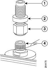
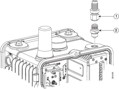
The Cisco Lightning Arrestor must be bulkhead-mounted onto the enclosure or router chassis. The lightning arrestor must be attached directly onto a well-grounded chassis through the threaded shaft of the lightning arrestor and the bulkhead adapter. See Figure 1.

Note![]() This part might be factory installed in an antenna port on the router when the router is shipped.
This part might be factory installed in an antenna port on the router when the router is shipped.
Note![]() When you install the lightning arrestor, follow the regulations or best practices applicable to lightning protection installation in your local area.
When you install the lightning arrestor, follow the regulations or best practices applicable to lightning protection installation in your local area.
Warning![]() Installation of the equipment must comply with local and national electrical codes. Statement 1074
Installation of the equipment must comply with local and national electrical codes. Statement 1074
Figure 1 Lightning Arrestor Detail (CGR-LA-NM-NF shown)
To install the lightning arrestor:
Step 1![]() Install the bulkhead N-connector adapter onto the appropriate antenna port on the router chassis. Tighten to a 6-to-7 ft-lbs torque rating.
Install the bulkhead N-connector adapter onto the appropriate antenna port on the router chassis. Tighten to a 6-to-7 ft-lbs torque rating.
Step 2![]() Install the N-plug end of the lightning arrestor onto the top of the bulkhead N-connector). Tighten to a 6-to-7 ft-lbs torque rating.
Install the N-plug end of the lightning arrestor onto the top of the bulkhead N-connector). Tighten to a 6-to-7 ft-lbs torque rating.
Step 3![]() Install the N-plug end of your antenna cable onto the N-jack of the lightning arrestor. Tighten to a 6-to-7 ft-lbs torque rating.
Install the N-plug end of your antenna cable onto the N-jack of the lightning arrestor. Tighten to a 6-to-7 ft-lbs torque rating.
Tell Us What You Think

|
Send your feedback about this document directly to the Connected Energy Documentation Team. |
Any Internet Protocol (IP) addresses and phone numbers used in this document are not intended to be actual addresses and phone numbers. Any examples, command display output, network topology diagrams, and other figures included in the document are shown for illustrative purposes only. Any use of actual IP addresses or phone numbers in illustrative content is unintentional and coincidental.
 Feedback
Contact Cisco
- Open a Support Case

- (Requires a Cisco Service Contract)