Feedback
Table Of Contents
General Descriptions of the Router Models
Cisco 851 and Cisco 871 Ethernet-to-Ethernet Routers
Router Ports on the Cisco 851 and Cisco 871 Back Panel
USB Port Power Allocation on the Cisco 871 Router
Cisco 857 and Cisco 877 ADSL-over-POTS Routers
Router Ports on the Cisco 857 and Cisco 877 Back Panel
Cisco 876 ADSL-over-ISDN Router
Router Ports on the Cisco 876 Back Panel
Router Ports on the Cisco 878 Back Panel
Integrated 802.11b/g Radio Module (Wireless Models Only)
Supported Cisco Radio Antennas (Wireless Models Only)
External Power-over-Ethernet Module (Optional)
LED Indicators on the PoE Module
Product Overview
This chapter provides an overview of the hardware features for the Cisco 851, Cisco 857, Cisco 871, Cisco 876, Cisco 877, and Cisco 878 routers. It contains the following sections:
•
General Descriptions of the Router Models
General Descriptions of the Router Models
This section provides a general description of each of the router models.
•
•
•
Cisco 851 and Cisco 871 Ethernet-to-Ethernet Routers
The Cisco 851 and Cisco 871 Ethernet-to-Ethernet routers can connect a corporate teleworker or a small office to an Internet service provider (ISP) over a broadband or Ethernet connection to a corporate LAN or to the Internet. The Cisco 851 and Cisco 871 routers are switch-capable routers that provide a 4-port Ethernet switch for the LAN. These routers are capable of bridging and multiprotocol routing between LAN and WAN ports.
Universal Serial Bus (USB) ports on the Cisco 871 router provide connection for USB devices such as security tokens, flash memory sticks, and printers.
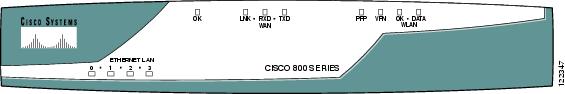
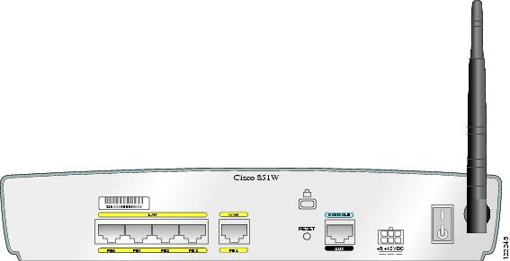
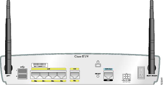
The front panels of the Cisco 851 and Cisco 871 routers are identical. (See Figure 1-1.) Figure 1-2 shows the back panel of the Cisco 851 router, and Figure 1-3 shows the back panel of the Cisco 871 router.
The Cisco 851 wireless model supports the use of a single 2.4-GHz antenna (see Figure 1-2), and the Cisco 871 wireless model supports the use of two 2.4-GHz antennas (see Figure 1-3).
Figure 1-1 Cisco 851 and Cisco 871 Router Front Panel
Figure 1-2 Cisco 851 Router Back Panel
Figure 1-3 Cisco 871 Router Back Panel with Antennas
Router Ports on the Cisco 851 and Cisco 871 Back Panel
The Cisco 851 and Cisco 871 routers have the following ports on the back panel:
•
•
•
•
USB Port Power Allocation on the Cisco 871 Router
The power available for each of the two USB ports is 500 mA. Power is dynamically allocated to each port as needed, up to 500 mA.
Cisco 857 and Cisco 877 ADSL-over-POTS Routers
The Cisco 857 and Cisco 877 routers are asymmetric digital subscriber line (ADSL)-over-plain old telephone service (POTS) routing devices. The routers have an integrated 4-port Ethernet switch for the LAN and an ADSL physical interface for the WAN, allowing the routers to connect a corporate telecommuter or small office to corporate LANs and the Internet.
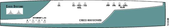
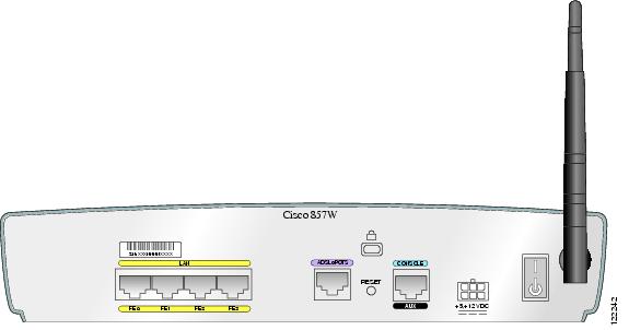
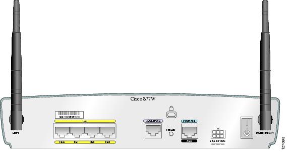
The front panels of the Cisco 857 and Cisco 877 routers are identical. (See Figure 1-4.) The back panels of these two routers are similar except for their model numbers, which differ. Figure 1-5 shows the back panel of a Cisco 857 router, and Figure 1-6 shows the back panel of a Cisco 877 router.
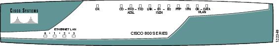
Figure 1-4 Cisco 857 and Cisco 877 Router Front Panel
Figure 1-5 Cisco 857 Router Back Panel, with Antenna Installed
Figure 1-6 Cisco 877 Router Back Panel, with Antennas Installed
Router Ports on the Cisco 857 and Cisco 877 Back Panel
The Cisco 857 and Cisco 877 routers have the following ports on the back panel:
•
•
•
Cisco 876 ADSL-over-ISDN Router
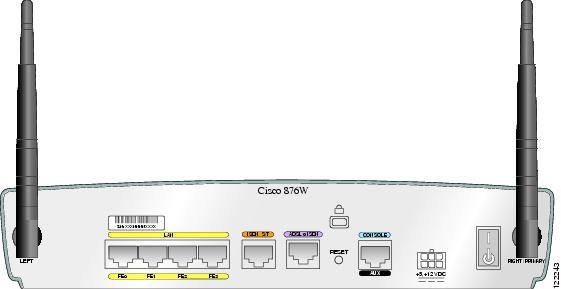
The Cisco 876 router is an asymmetric digital subscriber line (ADSL)—over—ISDN routing device. The router has an integrated 4-port Ethernet switch for the LAN and an ADSL physical interface for the WAN, and ISDN BRI WAN connectivity. This ISDN BRI interface can be used for normal WAN connections or can be configured as a backup connection for the ADSL WAN interface. These features allow the routers to connect a corporate telecommuter or a small office to a central office or an Internet service provider (ISP) over an ADSL interface.
Figure 1-7 shows the front panel of the Cisco 876 router, and Figure 1-8 shows the back panel.
Figure 1-7 Cisco 876 Router Front Panel
Figure 1-8 Cisco 876 Router Back Panel, with Antennas Installed
Router Ports on the Cisco 876 Back Panel
The Cisco 876 router has the following ports on the back panel:
•
•
•
•
•
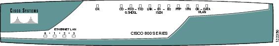
Cisco 878 SHDSL Router
The Cisco 878 router can connect a corporate telecommuter or small office to an Internet service provider (ISP) over multirate symmetrical high-data-rate digital subscriber lines (G.SHDSLs) to a corporate LAN and to the Internet.
The router has an integrated 4-port Ethernet switch for the LAN, a G.SHDSL physical interface for the WAN, and an ISDN BRI interface. The ISDN BRI S/T port can be used for remote management. The router is capable of bridging and multiprotocol routing between LAN and WAN ports.
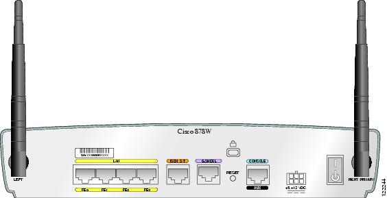
Figure 1-9 shows the front panel of the Cisco 878 router, and Figure 1-10 shows the back panel.
Figure 1-9 Cisco 878 Router Front Panel
Figure 1-10 Cisco 878 Router Back Panel with Antennas
Router Ports on the Cisco 878 Back Panel
The Cisco 878 router has the following ports on the back panel:
•
•
•
•
Feature Summary
Table 1-1 summarizes the features of these routers.
Hardware Features
This section provides an overview of the hardware features of Cisco 850 series and Cisco 870 series routers and includes the following topics:
•
•
•
•
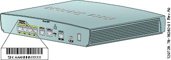
Serial Number Location
The serial number label for the router is located on the rear of the chassis, at the left edge (see Figure 1-11).
Figure 1-11 Serial Number Location
LED Indicators on the Routers
The router LEDs that indicate status or activity on the router are located on the front panel of the routers. Table 1-2 lists and describes the LEDs.
Integrated 802.11b/g Radio Module (Wireless Models Only)
The Cisco 850 series and Cisco 870 series wireless routers have an integrated IEEE 802.11b/g radio module that operates as a wireless access point in infrastructure mode. The wireless routers have two reverse-polarity threaded Neill-Concelman (RP-TNC) connectors on the back panel. The dipole swivel antennas that were shipped with the router connect to the RP-TNC connectors to operate the 802.11b/g radio module.
The wireless operations can be configured by using the Cisco Router and Security Device Manager (SDM) web-based application, or by using the Cisco IOS command-line interface (CLI). See the Cisco Router and Security Device Manager (SDM) Quick Start Guide or the Cisco Access Router Wireless Configuration Guide for more information.
Supported Cisco Radio Antennas (Wireless Models Only)
Table 1-3 lists the Cisco antennas that are supported on the Cisco 850 series and Cisco 870 series wireless routers.
Table 1-3 Cisco Antennas Supported on the Cisco 850 Series and Cisco 870 Series Wireless Routers
23.7786.51
Omnidirectional
2.2 dBi
This is the default antenna. Swivel-mount dipole antenna operating in the 2.4- to 2.5-GHz band. This antenna is designed for use with Cisco wireless products utilizing an RP-TNC connector. For more information, see the Cisco 2.4-GHz Swivel-Mount Dipole Antenna (23.7786.51) document.
AIR-ANT4941
Omnidirectional
2.2 dBi
Swivel-mount dipole antenna operating in the 2.4- to 2.5-GHz band. This antenna is designed for use with Cisco wireless products utilizing an RP-TNC connector. For more information, see the Cisco Aironet 2.4 Ghz Articulated Dipole Antenna (AIR-ANT4941) document.
AIR-ANT1728
Omnidirectional
5.2 dBi
Ceiling-mount antenna operating in the 2.4- to 2.5-GHz band. This antenna has a clip that allows it to be mounted to a drop-ceiling cross member. For more information, see the Cisco Aironet High Gain Omnidirectional Ceiling Mount Antenna (AIR-ANT1728) document.
Note
AIR-ANT3549
Patch
9 dBi
Wall-mount antenna operating in the 2.4- to 2.5-GHz band.
Note
AIR-ANT5959
Diversity omnidirectional
2.35 dBi
Ceiling-mount antenna operating in the 2.4- to 2.5-GHz band. This antenna has a clip that allows it to be mounted to a drop-ceiling cross member. For more information, see the Cisco Aironet 2 dBi Diversity Omnidirectional Ceiling Mount Antenna (AIR-ANT5959) document.
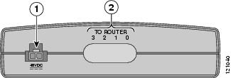
External Power-over-Ethernet Module (Optional)
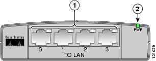
The optional external power-over-Ethernet (PoE) module is a standalone device that connects to the Ethernet ports on the router on one side (To ROUTER) and to powered devices (such as PCs, laptops, and IP phones) on the other side (To LAN). The PoE module has an independent power source that can provide inline power to devices connected to each of the four Ethernet ports, so that these devices do not need separate power sources.
Caution
Figure 1-12 Power-over-Ethernet Module Front Panel
Figure 1-13 Power-over-Ethernet Module Back Panel
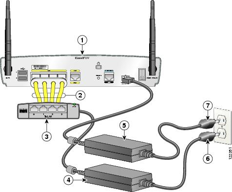
Figure 1-14 Installing the PoE Module
Cisco 870 series router
Router power adapter
Ethernet cables on the PoE module (four RJ-45 connectors in series)
PoE power plug
PoE module
Router power plug
PoE power adapter
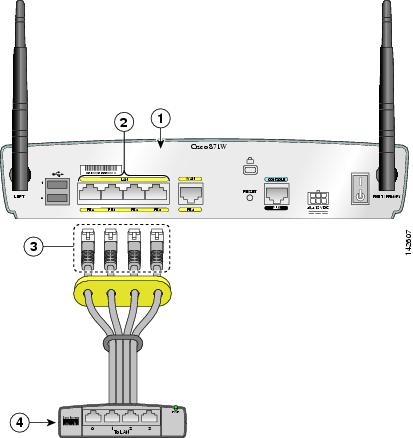
Figure 1-15 Connecting the PoE Module to the Router
Cisco 870 series router
Four RJ-45 Ethernet plugs, in series, from the PoE module (plug these into the Ethernet ports on the router)
RJ-45 Ethernet ports on the router
PoE module
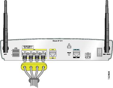
Figure 1-16 PoE Module Connected to the Router
LED Indicators on the PoE Module
Router Memory
Cisco 850 series and Cisco 870 series routers support the following types of memory:
Flash Memory
Flash memory stores the image of the ROMMON boot code, the Cisco IOS software, and the router configuration file. The router provides two onboard StrataFlash devices, one with 16 MB and the other with 4 MB of memory, for a total of 20 MB of onboard flash memory.
•
•
–
–
SDRAM
SDRAM stores the Cisco IOS software and provides memory for data created during packet processing. The router provides 128 MB of onboard SDRAM, with an expansion slot that allows an additional 64 MB or 128 MB, up to a maximum of 256 MB of SDRAM.
Router Hardware Security
The Cisco 850 series and Cisco 870 series routers have a Kensington security slot on the back panel. To secure the router to a desktop or other surface, use the Kensington lockdown equipment.
Regulatory Compliance
For compliance and safety information, see the Regulatory Compliance and Safety Information for Cisco 800 Series and SOHO Series Routers document that was shipped with the router.
For wireless models, also see the Declarations of Conformity and Regulatory Information for Cisco Access Products with 802.11a/b/g and 802.11b/g Radios document that was shipped with the router.