Cisco 850 Series and Cisco 870 Series Access Routers Hardware Installation Guide
Router and PoE Module Mounting Procedures

Table Of Contents

Router and PoE Module Mounting Procedures

Connecting Antennas to the Wireless Router

Mounting on a Table

Mounting on a Wall

Guidelines for Wall Mounting

Mounting the Router on a Wall

Mounting the PoE Module on a Wall

What to Do Next


Router and PoE Module Mounting Procedures


This chapter describes the procedures for mounting the following routers and the power-over-Ethernet (PoE) module:

Cisco 851 and Cisco 871 routers

Cisco 857 and Cisco 877 routers

Cisco 876 router

Cisco 878 router

This chapter contains the following sections:

Connecting Antennas to the Wireless Router

Mounting on a Table

Mounting on a Wall

What to Do Next

Connecting Antennas to the Wireless Router

Before you mount the router on a table or a wall, connect the antennas to the back panel. It is difficult to attach the antennas after the router has been mounted to a wall.

Mounting on a Table

The router and the PoE module can be mounted on a table or other flat horizontal surface.

To mount the router on a table, firmly place the router on a table. Do not cover or obstruct the router vents, which are located on the router sides.

To mount the PoE module on a table, place the PoE module near the router so that the Ethernet cables on the PoE module can easily connect to the router Ethernet ports.


Caution Do not cover or obstruct the router vents; otherwise, overheating could occur and cause damage to the router.

Mounting on a Wall

This section provides information for mounting the router and the PoE module on a wall.

Guidelines for Wall Mounting

You should meet the following guidelines when you mount the router or PoE module on a wall:

Mount the router with the front panel facing upward so that the LEDs are clearly visible.

Mount the router low enough for you to see the LEDs.

Mount the PoE module with the Ethernet cables (To ROUTER side) facing up, and the ports (To LAN side) facing down.

The Ethernet cables on the PoE module must easily connect to the Ethernet ports on the router.

The power supply must rest on a horizontal surface such as the floor or a table. If the power supply is not supported, the strain on the power adapter cable could cause it to disconnect from the connector on the router back panel.

Do not install the router, PoE module, or power supplies next to a heat source of any kind, including heating vents during winter.

Mounting the Router on a Wall

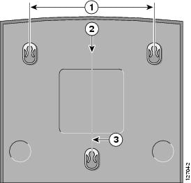
The router can be mounted on a wall by using the molded mounting brackets on the bottom of the router and three number-six, 3/4-in. (M3.5 x 20 mm) screws. You must provide the screws. Figure 3-1 shows the mounting brackets.


Caution If you are mounting the router on drywall, use three hollow-wall anchors to secure the three 1/8-in. (M3) screws. If the screws are not properly anchored, the strain of the network cable connections could pull the router from the wall. Use the drill bit size that is specified by the hollow-wall anchor manufacturer.

Figure 3-1 Mounting Brackets on the Bottom of the Router

1

Distance between two top mounting brackets (near the front panel)

3

Vertical distance between the top mounting brackets and the bottom bracket

2

Midpoint between the two top mounting brackets (near the front panel)


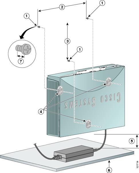
Figure 3-2 shows the locations of the mounting screws and the router mounting brackets, and the placement of the power adapter.

Figure 3-2 Mounting the Router on a Wall

1

Three number-six, 3/4 in. screws

5

Maximum distance between the router and the power adapter (6 ft. [1.8 m])

2

Distance between the top set of screws on the wall

6

Horizontal surface on which to place the power adapter

3

Vertical distance between the top screws and the bottom screw on the wall

7

Distance between the screw head and the wall (1/8 in. [0.32 cm])

4

Mounting brackets


Perform the following steps to mount the router on a wall:


Step 1 Select a location on the wall on which you wish to mount the router. Using Figure 3-1 as a reference, draw a horizontal line measuring 6.69 in. (17.0 cm) long.

Step 2 Make sure that the horizontal line is level. Drill two holes for the mounting screws, one at each end of the line. Use the drill bit size that is specified by the screw or hollow-wall anchor manufacturer.

Step 3 Measure 3.345 in. (8.5 cm) from either one of the screw holes to determine the midpoint between the two top mounting screws.

Step 4 From the midpoint, measure a vertical distance of 5.55 in. (14.1 cm) to determine the location for the bottom mounting screw, and then drill a hole.

Step 5 Anchor the screws into the wall, leaving 1/8 in. (0.32 cm) between the screw head and the wall for mounting the router.

Step 6 Hang the router on the screws as shown in Figure 3-2. Secure the screws into the latches of the mounting brackets.

Step 7 Place the power adapter on a horizontal surface. (See Figure 3-2.)


Mounting the PoE Module on a Wall

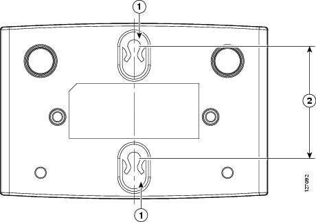
The PoE module can be mounted on a wall near the router. Figure 3-3 shows the location of the mounting brackets on the bottom panel of the PoE module.

Figure 3-3 Mounting Brackets on the Bottom Panel of the PoE Module

1

Mounting brackets

2

Distance between the mounting brackets (1.70 in. [4.32 cm])


Perform the following steps to mount the PoE module on a wall:


Step 1 Select a location on the wall on which you wish to mount the PoE module. See Figure 3-3 for the locations of the mounting brackets on the bottom panel.

Step 2 Mark on the wall where the mounting screws will be anchored, making sure that the marks line up vertically. Drill two holes 1.70 in. (4.32 cm) apart on the wall, using the drill bit size that is specified by the screw or hollow-wall anchor manufacturer.

Step 3 Anchor the screws into the wall, leaving 1/8 in. (0.32 cm) between the screw head and the wall for mounting the PoE module.

Step 4 Hang the PoE module on the wall, and secure the screws into the latches of the mounting brackets.

Step 5 Place the power supply on a horizontal surface.


What to Do Next

Connect devices to the router by following the instructions in Chapter 4 "Router Cabling Procedures."