[an error occurred while processing this directive]

Support

Overview

Hierarchical Navigation

Downloads

 Feedback

Table Of Contents

Overview

Hardware Overview

Front View

LEDs on the NSE-100

LEDs on the NSE-150

LEDs on the NPE-G100

Rear View

System Board NSE-100

System Board—NSE-150

System Board—NPE-G100

System Management Functions

Checking the Shipping Container Contents

Installation Checklist


Overview


The Cisco 7304 router is a high-performance Enterprise Edge LAN/WAN integration and service provider aggregation router.

This chapter provides a quick hardware overview and installation instructions for the Cisco 7304 router. For functional information, see "Starting and Configuring," the "Functional Overview" section. For system specifications and port and cabling specifications, see "Specifications."

This chapter includes the following sections:

Hardware Overview

Checking the Shipping Container Contents

Installation Checklist


Warning Before you install, operate, or service the system, read the Site Preparation and Safety Guide. This guide contains important safety information you should know before working with the system.


Hardware Overview

The Cisco 7304 router supports the following features:

Online insertion and removal (OIR)—Allows you to add, replace, or remove line cards without interrupting the system

Environmental monitoring and reporting functions—Allow you to maintain normal system operation by resolving adverse environmental conditions prior to loss of operation

Downloadable software—Allows you to load new images into Flash memory remotely, without having to physically access the router, for fast, reliable upgrades

Small form-factor—Four rack-units high with stacking capability: 6.94 in. x 17.6 in. x 20.5 in. (17.63 cm x 44.70 cm x 52.07 cm)

Front to back airflow—Allows you to mount the router from either front or back into 2-post and 4-post 19- inch and 21-23 inch racks

The following sections provide illustrations and a brief overview of the Cisco 7304 router:

Front View

LEDs on the NSE-100

LEDs on the NSE-150

LEDs on the NPE-G100

Rear View

System Board NSE-100

System Board—NSE-150

System Board—NPE-G100

System Management Functions

Front View

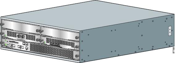
Figure 1-1 Cisco 7304 Router—Front View (NSE-100 Shown)

The Cisco 7304 router supports:

A processing engine containing both I/O functionality and the route processor. The following processing engines are available:

Network Services Engine 100 (NSE-100)—Three Ethernet interfaces: three physical Ethernet ports, two Gigabit Ethernet (1000-Mbps) ports and a Fast Ethernet management (10/100-Mbps) port with an RJ-45 connector

Network Services Engine 150 (NSE-150)- Five Ethernet interfaces: four Gigabit Ethernet small form factor pluggable (SFP) ports and a Fast Ethernet management (10/100-Mbps) port with an RJ-45 connector

Network Processing Engine (NPE-G100)—Three Gigabit Ethernet interfaces: six physical Gigabit Ethernet ports, three small form factor pluggable (SFP) ports and three RJ-45 ports. Any three are usable at any one time

A 256-MB CompactFlash Disk

Power supplies that are available in four options: single AC, dual AC, single -48 VDC, and
dual -48 VDC

LEDs on the NSE-100

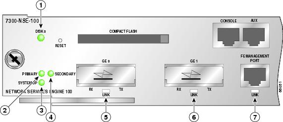
NSE-100 LED information is in Figure 1-2 and Table 1-1 below.

Figure 1-2 LEDs on the NSE-100

Table 1-1 NSE-100 LEDs 

LED Label
Color
State
Function

DISK 0

Green/Yellow

Green

CompactFlash Disk is being accessed.


Yellow

CompactFlash Disk access failure.


Off

Default state on power up.

GE0 LINK

Green/Yellow

Green

Gigabit Ethernet port 0 is up.


Yellow

Gigabit Ethernet port 0 line protocol is down due to a link error or other conditions.


Off

Default state on power up, Gigabit Ethernet port 0 has been administratively shut down, or a fatal hardware error has occurred.

GE1 LINK

Green/Yellow

Green

Gigabit Ethernet port 1 is up.


Yellow

Gigabit Ethernet port 1 line protocol is down due to a link error or other conditions.


Off

Default state on power up, Gigabit Ethernet port 1 has been administratively shut down, or a fatal hardware error has occurred.

FE Management Port LINK

Green/Yellow

On

Fast Ethernet physical link is up.


Yellow

Line protocol is down due to a link error.


Off

Default state on power up or has been administratively shut down.

PRIMARY

Green

On

NSE is up and running.


Off

Default state on power up.

SECONDARY

Green

On

Green when this NSE is the standby NSE.


Off

Off when the NSE is not active.

SYSTEM-UP

Green/Yellow

Green

Cisco IOS is up and running.


Yellow

ROMmon is booting up, ROMmon detects a fatal hardware error, or ROMmon is hanging before the system completes the bootup process.


Off

ROMmon has completed the bootup process and the system either is in the autoboot stage or is waiting for a user command at a rommon#> prompt.


LEDs on the NSE-150

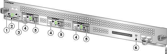
NSE-100 LED information is in Figure 1-3 and Table 1-1 below.

Figure 1-3 LEDs on the NSE-150

Table 1-2

LED Label
Color
State
Function

ACTIVE

Green

On

NSE is up and running.


Off

NSE is off. Default state on power up.

SYSTEM-UP

Green/Yellow

Green

Cisco IOS is up and running.


Yellow

ROMmon is booting up, ROMmon detects a fatal hardware error, or ROMmon is hanging before the system completes the bootup process.


Off

ROMmon has completed the bootup process and the system either is in the autoboot stage or is waiting for a user command at a rommon#> prompt, or the NSE is off.

STANDBY

Green

On

The NSE is the standby NSE in a High Availability configuration.


Off

The NSE is not running or is running as the primary NSE.

GIGABIT ETHERNET 0 LINK

Green/Yellow

Green

Gigabit Ethernet port 0 is up.


Yellow

Gigabit Ethernet port 0 line protocol is down due to a link error or other conditions.


Off

Default state on power up, Gigabit Ethernet port 0 has been administratively shut down, or a fatal hardware error has occurred.

GIGABIT ETHERNET 1 LINK

Green/Yellow

Green

Gigabit Ethernet port 1 is up.


Yellow

Gigabit Ethernet port 1 line protocol is down due to a link error or other conditions.


Off

Default state on power up, Gigabit Ethernet port 1 has been administratively shut down, or a fatal hardware error has occurred.

GIGABIT ETHERNET 2 LINK

Green/Yellow

Green

Gigabit Ethernet port 2 is up.


Yellow

Gigabit Ethernet port 2 line protocol is down due to a link error or other conditions.


Off

Default state on power up, Gigabit Ethernet port 2 has been administratively shut down, or a fatal hardware error has occurred.

GIGABIT ETHERNET 3 LINK

Green/Yellow

Green

Gigabit Ethernet port 3 is up.


Yellow

Gigabit Ethernet port 3 line protocol is down due to a link error or other conditions.


Off

Default state on power up, Gigabit Ethernet port 3 has been administratively shut down, or a fatal hardware error has occurred.

DISK 0

Green/Yellow

Green

CompactFlash Disk is being accessed.


Yellow

CompactFlash Disk access failure.


Off

Default state on power up.

FE Management Port LINK

Green/Yellow

Green

Fast Ethernet physical link is up, line protocol is up.


Yellow

Line protocol is down due to a link error.


Off

Default state on power up or has been administratively shut down.


NSE-150 LEDs

LEDs on the NPE-G100

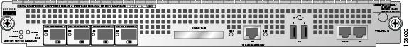
NPE-G100 LED information is in Figure 1-4 below.

Figure 1-4 LEDs on the NPE-G100
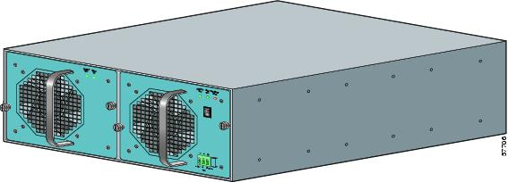
No.
LED Label
LED
Purpose
Color
LED Color Status
1

Active

Active

Indicates this NPE-G100 is the active NPE

Green

Solid green when this NPE is the active NPE.


Off

Off when this NPE is not the active NPE.

2

Standby

Standby

Indicates this NPE-G100 is the redundant or secondary NPE

Green

Solid green when this NPE is the standby NPE.


Off

Off when this NPE is not active.

3

System-Up

System-Up

System status

Green

Green when Cisco IOS is up and running.


Amber

When ROMmon is booting up

When ROMmon is hanging before the system completes the bootup process

When ROMmon detects a fatal hardware error


Off

Between amber when ROMmon is booting, and solid green when Cisco IOS is up and running.

4

LINK
(Interfaces 0, 1, 2)

RJ-45 and SFP ports

Green

On, indicating that a link has been established.

Off

Off when LINK is not up.

5

EN (Enable) (Interfaces 0, 1, 2)

RJ-45 ports only

Green

On if the RJ-45 port is selected.

Off

Off if the SFP port is selected.

6

Disk 0

CompactFlash Disk

Green

Solid green when the disk is being used.

Blinking when the disk is being accessed.


Rear View

Figure 1-5 Cisco 7304 Router—Rear View

The rear of the Cisco 7304 router has two fan airflow vents. (See Figure 1-5.)

Two replaceable internal fans draw cooling air out of the chassis and across internal components to maintain an acceptable operating temperature. (See Figure 1-5.) The two fans are located at the rear of the chassis.

System Board NSE-100

Internally, the NSE-100 contains the following components:

256 or 512 MB SDRAM memory1

Processors

Reduced instruction set computing (RISC) RM7000 microprocessor that operates at an internal clock speed of 350 Mhz. The RM7000 processor maintains and executes the system management functions for the Cisco 7304 router. The processor also performs some memory and environmental monitoring functions.

The Parallel eXpress Forwarding (PXF) processors enable parallel IP multipacket processing functions, working with the Route Processor to provide accelerated packet switching, as well as accelerated IP Layer 3 feature processing.

System controller

The system controller provides hardware logic to interconnect the processors and SDRAM. The Cisco 7304 router has one system controller.

Cache memory

The processor has three levels of cache: primary and secondary cache that are internal to the microprocessor with secondary unified cache for data and instruction, and tertiary, 2-MB external cache.

Four environmental sensors for monitoring the internal temperature of the cooling air as it leaves the chassis

Upgradeable boot ROM for storing sufficient code for booting the Cisco IOS software

System Board—NSE-150

Internally, the NSE-150 contains the following components:

2 GB SDRAM

Processors

Route Processor that maintains and executes the system management functions for the Cisco 7304 router.

The Parallel eXpress Forwarding (PXF) processors enable parallel IP multipacket processing functions, working with the Route Processor to provide accelerated packet switching, as well as accelerated IP Layer 3 feature processing.

2 MB NVRAM for storing the system configuration and environmental monitoring logs. NVRAM uses a lithium battery to maintain its contents when disconnected from power.

Internal Flash Disk drive (bootdisk:) in addition to the external Flash Drive (disk0:)

Upgradeable boot ROM for storing sufficient code for booting the Cisco IOS software

Four environmental sensors for monitoring the internal temperature of the cooling air as it leaves the chassis

System Board—NPE-G100

Internally, the NPE-G100 contains of the following components:

BCM 1250 processor system:

Microprocessor operates at an internal clock speed of 800 Mhz.

Hardware logic to interconnect the processor, dual double data rate synchronous dynamic random-access memory (DDR-SDRAM), hypertransport (HT) interface, the generic PCI bus, and the two midplanes.

Cache memory—The NPE-G100 has two levels of cache: primary and secondary cache that are internal to the BCM 1250 processor system with secondary unified cache for data and instruction.

DDR-SDRAM for providing code, data, and packet storage.

Three environmental sensors for monitoring the cooling air as it enters, moves across the system board, and leaves the chassis.

Three Gigabit Ethernet interfaces (six connectors: three Gigabit Ethernet SFP [optical] and three 10/100/1000 RJ-45 [copper]). For each interface, either the Gigabit Ethernet SFP or the RJ-45 port is available. The ports are linked directly to the BCM 1250 processor system.

CompactFlash Disk: Stores sufficient code for booting the Cisco IOS boot loader image (bootdisk:).

NVRAM for storing the system configuration and environmental monitoring logs. NVRAM uses a lithium battery to maintain its contents when disconnected from power.

Upgradeable boot ROM for storing the ROMmon image and upgrading the system to newer versions of the ROMmon image. There are two upgradeable boot ROMs for storing the ROMmon image.

Non-upgradeable boot ROM provides a "golden copy" of the default ROMmon image.

Auxiliary port with full data terminal equipment (DTE) functionality.

Console port with full data communications equipment (DCE) functionality.

ECC (error correction code) system memory and internal L2 cache support.

System Management Functions

The Cisco 7304 performs the following system management functions:

Sending and receiving routing protocol updates

Managing tables, caches, and buffers

Monitoring interface and environmental status

Providing Simple Network Management Protocol (SNMP) management

Booting and reloading images

Managing line cards (including recognition and initialization during online insertion and removal)

High availability (HA) support and management for two NPE-G100s, one active and one standby

Routing and forwarding traffic


Caution Two NPE-G100s, two NSE-100s, or two NSE-150s are supported in the Cisco 7304. You cannot use two different processors in the same router, however.


Note For a chassis footprint, additional dimensions, and clearance requirements for the Cisco 7304 router, see the "Preparing to Install the Cisco 7304 Router" section in "Installation and Maintenance."


The Cisco 7304 router supports multiprotocol, multimedia routing and bridging with a wide variety of protocols and line cards.

Checking the Shipping Container Contents

Use the Cisco 7304 Components List to check the contents of the Cisco 7304 router shipping container. Do not discard the shipping container. You need the container if you move or ship the Cisco 7304 router in the future.

Table 1-3 Cisco 7304 Components List

Component
Description
Received

Chassis

Cisco 7304 chassis configured with an AC or DC power supply, line cards, and a CompactFlash Disk


Accessories:

Rack-mount and cable-management kit

Power cables

Documentation

The following accessories might arrive in separate shipping containers:

Two rack-mount brackets, two cable-management brackets, four M4 x 20-mm Phillips flathead screws. Eight 8-18 x .37-in. screws for a 19-inch rack; 8 x .755-in. screws for a
21-inch-23-inch rack

An AC power cable, if an AC power supply was ordered

If ordered, router hardware and software documentation set and the Cisco Documentation CD-ROM package1


Optional Equipment

Examples: Line cards, GBICs, SFP modules, network interface cables, transceivers, special connectors


1 Titles and quantities of documents will vary. You must order the type and quantity of documentation sets when you order the hardware.


Note We no longer ship the entire router documentation set automatically with each system. You must specifically order the documentation as part of the sales order. If you ordered documentation and did not receive it, we will ship the documents to you within 24 hours. To order documents, contact a customer service representative.


Installation Checklist

To assist you with your installation and to provide a historical record of what was done by whom, photocopy the Cisco 7304 Router Installation Checklist, Table 1-4. Indicate when each procedure or verification is completed. When the checklist is completed, place it in your site log along with the other records for your new router.

Table 1-4 Cisco 7304 Router Installation Checklist 

Task
Verified By
Date

Date router received


Router and all accessories unpacked


Safety recommendations and guidelines reviewed


Types and numbers of interfaces verified


Installation Checklist copied


Site log established and background information entered


Site power voltages verified


Site environmental specifications verified


Required passwords, IP addresses, device names, and so on, available


Required tools available


Network connection equipment available


Router mounted in rack (optional)


Cable-management brackets installed (optional but recommended)


AC power cable(s) connected to AC source(s) and router


DC power cable(s) connected to DC source(s) and router


I/O ports operational


Line card or PCI port adapters are operational


Network interface cables and devices connected


ASCII terminal attached to console port


Console port set for 9600 baud, 8 data bits, no parity, and 2 stop bits (9600 8N2)


System power turned on


System boot complete (SYSTEM-UP LED is on)


Correct hardware configuration displayed after system banner appears


1 On November 3, 2003, the 512 MB SDRAM memory option became the default SDRAM memory option for the NSE-100 Processor. The 256 MB SDRAM memory option is still available as a spare, but the 128 MB SDRAM memory option that was once available for the NSE-100 Processor became unavailable for the NSE-100 Processor.


[an error occurred while processing this directive]