Downloads |
 Feedback Feedback
|
Table Of Contents
Processor and Memory Specifications and Configurations
Gigabit Ethernet SFP Port and Cabling Information
Gigabit Ethernet RJ-45 Port Pinouts
NSE-100 and NSE-150 Fast Ethernet RJ-45 Port Pinouts
Console and Auxiliary Port Signals and Pinouts
Specifications
This appendix provides system and component specifications for the Cisco 7304 router.
The following topics are found in this appendix:
•
Processor and Memory Specifications and Configurations
•
•
•
•
•
System Specifications
The specifications for the Cisco 7304 router are listed in Table A-1.
Table A-1 Cisco 7304 System Specifications
Dimensions (H x W x D)
6.94 in. x 17.6 in. x 20.5 in. (17.63 cm x 44.70 cm x 52.07 cm)
Weight
28 lbs. (12.73 kg) (Chassis without line cards)
Heat dissipation
700W (2387 BTU) maximum
AC-input power
800 VA maximum (single supply configuration)
AC-input voltage rating
100-240 VAC1 wide input with power factor correction
AC-input current rating
Rated for 8A when Vin = 100 VAC or 4A when Vin = 200 VAC.
AC-input frequency rating
50-60 Hz2
AC-input cable
18 AWG3 three-wire cable, with a three-lead IEC-320 receptacle on the power supply end, and a country-dependent plug on the power source end
DC-input power
750 VA maximum configuration
DC-input voltage ratings
-48 VDC nominal, maximum range -48 VDC to -60 VDC (-40.5 to
-72 VDC supply tolerance)DC-input current ratings
16A at -48 VDC (18.5A at -40.5 VDC, 10.4A at -72 VDC supply tolerance)
DC-input cable
12 AWG only
1 VAC = volts alternating current
2 Hz = hertz
3 AWG = American Wire Gauge
Processor and Memory Specifications and Configurations
Table A-2 NSE-100 Processor and Memory Specifications
SDRAM1
256 or 512 MB
1
256-MB or 512-MB SODIMM
U19
Non-upgradeable boot ROM
512 KB
1
OTP2 ROM for the ROM monitor program (ROMmon)
U11
Upgradeable boot ROM
1 MB
2
Programmable ROM
U14, U34
Flash memory
disk 0: 64 MB, 128 MB, or 256 MB
bootdisk: 32 MB2
CompactFlash Disks
P2 (bootdisk:), P3 (disk0:)
Primary cache
16 KB (instruction), 16 KB (data)
—
RM7000 processor; internal cache
U2
Secondary cache
256 KB
—
RM7000 processor; internal unified instruction and data cache
U2
Tertiary cache
1 MB (fixed)
—
RM7000 processor; external cache
U5, U32, U33
1 On November 3, 2003, the 512 MB SDRAM memory option became the default SDRAM memory option for the NSE-100 Processor. The 256 MB SDRAM memory option is still available as a spare, but the 128 MB SDRAM memory option that was once available for the NSE-100 Processor became unavailable for the NSE-100 Processor.
2 OTP = one-time programmable. Although the OTP ROMmon cannot be upgraded, the boot code can be upgraded using the Cisco IOS software. If the boot code is upgraded, the updated boot code is stored in upgradeable boot ROM.
Table A-4 NPE-G100 Processor and Memory Specifications
SDRAM
1 GB
2
2 512 MBSODIMMs
J3, J4
Non-upgradeable boot ROM
512 KB
1
OTP1 ROM for the ROM monitor (ROMmon)
U15
NVRAM
512 KB
2
Configuration and crash information files
U1, U7
Upgradeable
boot ROM1 MB
2
Programmable ROM
U26, U64
Flash memory
disk0: 256 MB
bootdisk: 32 MB
1
CompactFlash Disks
External (disk0:)
Primary cache
16 KB (instruction), 16 KB (data)
—
BCM 1250 processor system, internal cache
U24
Secondary cache
512 KB
—
BCM 1250 processor system; internal, unified instruction and data cache
U24
1 OTP = one-time programmable. Although the OTP ROMmon cannot be upgraded, the boot code can be upgraded using the Cisco IOS software. If the boot code is upgraded, the updated boot code is stored in upgradeable boot ROM.
Table A-6 NPE-G100 SODIMM Configurations—Configurable Memory
1 GB
J3 and J4
2 512-MB SODIMMs
7304-MEM-G100-1GB=
Gigabit Ethernet SFP Port and Cabling Information
For information on the GBICs that are supported on the NSE-100 and the SFPs that are supported on the NSE-150, see the Cisco 7304 Network Services Engine Installation and Configuration Guide.
For information on the SFPs that are supported on the NPE-G100, see the "SFP Port and Cabling Information" section of the Cisco 7304 Network Processing Engine Installation and Configuration Guide.
Gigabit Ethernet RJ-45 Port Pinouts
The Cisco 7304 router has RJ-45 ports for either two or three 10/100/1000 Ethernet/Fast Ethernet/Gigabit Ethernet connections, depending on whether you have an NSE-100 or NPE-G100 installed (the NSE-150 only uses SFPs for Gigabit Ethernet connectivity). The RJ-45 ports support IEEE 802.3ab (Gigabit Ethernet) and IEEE 802.3u (Fast Ethernet) interfaces compliant with 10BASET, 100BASETX, and 1000BASET specifications.
The RJ-45 ports support standard straight-through and crossover Category 5 UTP cables with RJ-45 connectors. Cisco Systems does not supply Category 5 UTP cables; these cables are available commercially.
Warning
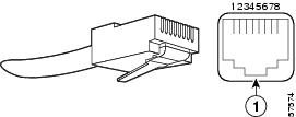
Figure A-1 shows an RJ-45 port and connector. Table A-8Table A-9 lists the pinouts and signals for the RJ-45 port.
Figure A-1 RJ-45 Port and Connector
Table A-8 RJ-45 Receptacle Pinouts
1
TX DATA+1
Tx A+
2
TX DATA-
Tx A-
3
RX DATA+2
Rx B+
4
N/C
Tx C+
5
N/C
Tx C-
6
RX DATA-
Rx B-
7
N/C
Rx D+
8
N/C
Rx D-
1 TX DATA = Transmit Data
2 RX DATA = Receive Data
NSE-100 and NSE-150 Fast Ethernet RJ-45 Port Pinouts
The Cisco 7304 router NSE-100 has RJ-45 ports for the one Fast Ethernet connection. The RJ-45 ports support IEEE 802.3,( Ethernet), and IEEE 802.3u (Fast Ethernet) interfaces compliant with 10BASET and 100BASETX specifications.
The RJ-45 port supports standard straight-through and crossover Category 5 UTP cables with RJ-45 connectors. Cisco Systems does not supply Category 5 UTP cables; these cables are available commercially.
Warning
Figure A-2 shows an RJ-45 port and connector. Table A-9Table A-9 lists the pinouts and signals for the RJ-45 port.
Figure A-2 RJ-45 Port and Connector
Table A-9 RJ-45 Receptacle Pinouts
1
TxD+2
2
TxD-
3
RxD+3
6
RxD-
1 Any pin not referenced is not connected.
2 TxD = Transmit Data
3 RxD = Receive Data
Note
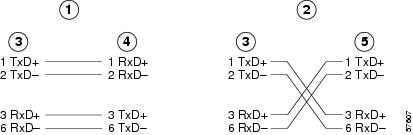
Use the pinouts shown in Figure A-3 for straight-through and crossover twisted-pair cable connections for your RJ-45 interface cabling requirements.
Figure A-3 Ethernet Pinouts—Straight-Through or Crossover Cable
Straight-though cable pinout, Ethernet port to a hub or repeater
Hub
Crossover cable pinout, Ethernet port to a DTE
DTE
Ethernet port
To determine whether a UTP cable is a crossover cable or a straight-through cable, hold the two RJ-45 connectors next to each other so you can see the colored wires inside the ends.
Examine the sequence of colored wires to determine the type of cable, as follows:
•
•
Console and Auxiliary Port Signals and Pinouts
The Cisco 7304 router does not support Data Carrier Detect (DCD). Table A-10 lists the RJ-45 console port signals.
Table A-11 lists the RJ-45 auxiliary port signals.