Downloads |
 Feedback Feedback
|
Table Of Contents
Installing and Removing Line Cards
Preprovisioning Line Card Slots
Removing and Installing Line Cards
Removing the Cisco 10008 Front Cover
Installing Full-Size Line Cards
Replacement Installation Guidelines
Installing Half-Height Line Cards
Replacement Installation Guidelines
Installing the Half-Height Line Card Carrier
Installing a Half-Height Line Card Into a Carrier
Installing SFP Modules or GBIC Modules
Guidelines for Using SFP Modules or GBIC Modules
Installing an SFP Module or GBIC Module
Attaching Multimode and Single-Mode Optical Fiber Cables
Attaching RJ-45 Ethernet Cables
Attaching the 24-Port Channelized E1/T1 Line Card Adapter Cable
Attaching the 4-Port Channelized T3 Half-Height Line Card Optional Y-Cables
Using the Cable-Management Bracket
Removing an SFP Module or GBIC Module
Removing Half-Height Line Cards and Carrier
Removing a Half-Height Line Card
Using show Commands to Verify Line Card Status
Using show Commands to Display Line Card Information
Using the ping Command to Verify Network Connectivity
Installing and Removing Line Cards
This chapter provides information about line cards and describes how to install or remove line cards on the Cisco 10005 and Cisco 10008 routers. This chapter contains the following sections:
•
Preprovisioning Line Card Slots
•
•
•
•
•
•
•
Handling Line Cards
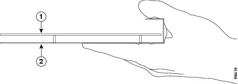
Each line card circuit board is mounted to a metal carrier and is sensitive to electrostatic discharge (ESD) damage. Before you begin installation, read the "Required Tools and Equipment" section on page 16-1 in Chapter 16, "Preparing for Installation" for a list of parts and tools required for installation.
Figure 17-1 shows how to hold the line card properly.
Caution
Figure 17-1 Handling a Line Card
When a slot is not in use, a blank faceplate must fill the empty slot to allow the router or switch to conform to electromagnetic interference (EMI) emissions requirements and to allow proper airflow across the installed modules. If you plan to install a line card in a slot that is not in use, you must first remove the blank faceplate.
Caution
Online Insertion and Removal
All line cards in the Cisco 10000 series routers support online insertion and removal (OIR). However, it is wise to shut down the interface before removing a line card that has active traffic moving through it. Removing a line card while traffic is flowing through the ports can cause system disruption. Once the line card is inserted, the ports can be brought back up.
If you remove and replace the line card in the same slot, the system automatically downloads the necessary configuration information from the Performance Routing Engine (PRE); you do not need to configure the new line card. After the software downloads the information, the system recognizes only those interfaces that match the previous line card configuration (configured as up).
Note
OIR allows you to install and replace line cards while the router is operating; you do not need to notify the software or shut down the system power, although you should not run traffic through the line card you are removing while it is being removed. OIR is a method that is seamless to end users on the network and maintains all routing information.
Caution
Preprovisioning Line Card Slots
Before you install a line card, you might want to preprovision the line card slot.
Preprovisioning a line card slot downloads software to the line card slot for the line card you are planning to install. Preprovisioning allows you to prepare in advance a complete configuration for the line card, including items you normally need to configure after initially configuring the line card, such as PVCs under an ATM line card or VLANs under an Ethernet line card.
Resetting a line card reloads line card software without having to manually insert and remove the line card.
See the Cisco 10000 Series Router Line Card Configuration Guide for more information on preprovisioning line card slots and resetting line card slots.
Slot and Subslot Locations
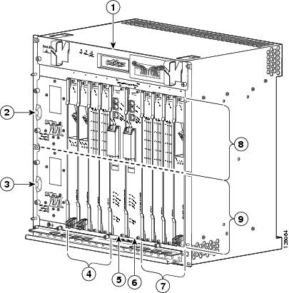
Figure 17-2 and Figure 17-3 show line card and half-height line card slot and subslot locations on the Cisco 10008 router and the Cisco 10005 router.
Figure 17-2 Line Card Slots and Subslots—Cisco 10008 Router
Blower module
PRE slot 0B
Primary PEM
Line card slots 5 to 8
Redundant PEM
Subslot 0
Line card slots 1 to 4
Subslot 1
PRE slot 0A
The Cisco 10000 line cards can be installed in slot 1 through slot 8. Cisco 10000 half-height line cards can be installed in subslot 0 or subslot 1 of slot 1 through slot 8 using a carrier.
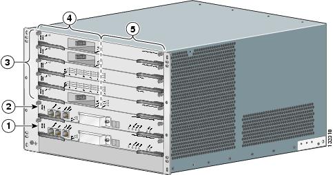
Figure 17-3 Line Card Slots and Subslots—Cisco 10005 Router
PRE slot A
Subslots 1/0 (top) to 5/0 (bottom)
PRE slot B
Subslots 1/1 (top) to 5/1 (bottom)
Line card slots 1 (top) to 5 (bottom)
The Cisco 10000 line cards can be installed in slot 1 through slot 5. Cisco 10000 half-height line cards can be installed in subslot 0 or subslot 1 of slot 1 through slot 5 using a carrier.
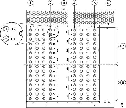
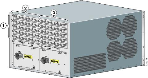
Figure 17-4 and Figure 17-5 provide illustrations of the BNC connectors and line card slots and subslots on the rear of the router.
Figure 17-4 BNC Connectors on the Rear of the Cisco 10008 Router
Line card slot 8
Line card slot 1
Line card slot 5
Power supply
Blower module
Half-height line card subslot 0
Line card slot 4
Half-height line card subslot 1
Figure 17-5 BNC Connectors on the Rear of the Cisco 10005 Router
Line card slots 1 (top) to 5 (bottom)
Subslots 1/0 (top) to 5/0 (bottom)
Subslots 1/1 (top) to 5/1 (bottom)
Also see Appendix A, "Cisco 10005 Extender Card Information" for information about the extender card which must be used with the 8-port unchannelized E3/T3 line card in the Cisco 10005 chassis.
All Cisco 10005 line cards connect to a backplane in the center of the chassis, and require extender cards to deliver the alarm, BITS clock, and DS3 signals to the rear of the chassis to make them accessible. The Cisco 10005 alarm extender card and T3/E3 extender card extend and terminate these signals.
Removing and Installing Line Cards
Some early Cisco 10008 chassis were shipped with front covers. The Cisco 10005 chassis has no front cover.
•
–
–
–
–
•
Removing the Cisco 10008 Front Cover
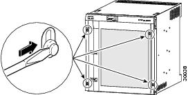
Use the following procedure to remove the front cover from the Cisco 10008 router (Figure 17-6 and Figure 17-7).
•
•
•
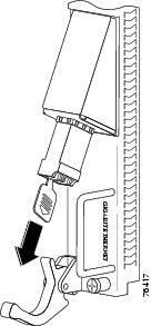
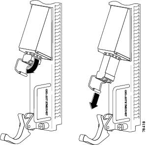
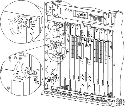
Figure 17-6 Inserting a Screwdriver Blade into a Bezel Latch
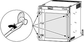
Figure 17-7 Unlocking the Bezel Latch
Step 1
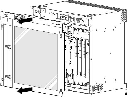
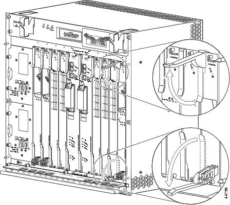
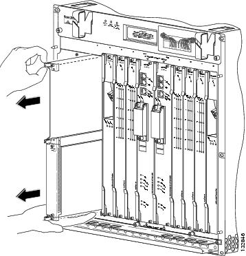
Repeat this procedure for all four bezel latches and then remove the latches (Figure 17-8).
Figure 17-8 Removing the Front Cover from the Cisco 10008 Router
Step 2
If you are installing a line card, go to the "Installing Full-Size Line Cards" section or the "Installing Half-Height Line Cards" section.
If you are removing a line card, go to the "Removing Full-Size Line Cards" section or the "Removing Half-Height Line Cards and Carrier" section.
Installing Full-Size Line Cards
This section provides step-by-step instructions for installing a full-size line card.
Warning
Use the following procedure to install a full-size line card into any of the eight line card slots (slots 1 through 8) available in the Cisco 10000 chassis.
Note
Replacement Installation Guidelines
If you replace a line card in the same slot, the system automatically downloads the necessary configuration information from the Processor Route Engine (PRE); you do not need to configure the new line card. After the software downloads the information, the system recognizes only those interfaces that match the previous line card configuration (configured as up).
Caution
Caution
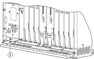
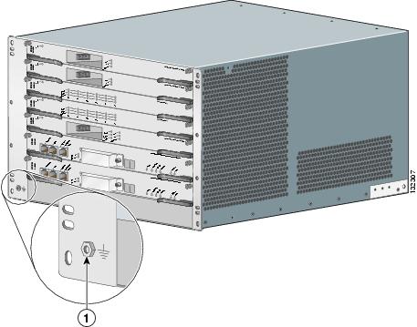
Figure 17-9 and Figure 17-10 show the ESD connections on the routers.
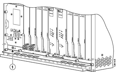
Figure 17-9 ESD Chassis Connection—Cisco 10008 Router
Figure 17-10 ESD Chassis Connection—Cisco 10005 Router
Step 1
Note
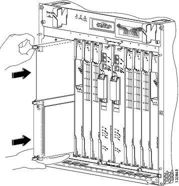
Step 2
Figure 17-11 Removing the Blank Faceplate
Step 3
Step 4
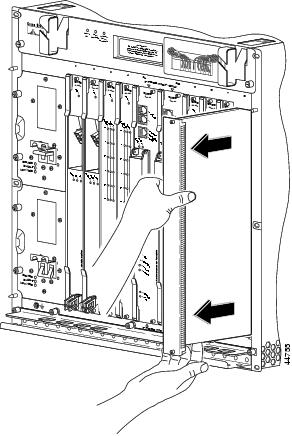
Figure 17-12 Inserting a Full-Size Line Card
Step 5
Figure 17-13 Closing the Ejector Levers
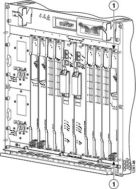
Step 6
Figure 17-14 Captive Screw Locations
Caution
Warning
Warning
The line card cycles through its power-on self-test (POST). The FAIL LED lights during portions of the POST, but remains off after POST on a properly working line card. If the FAIL LED remains on, go to Chapter 18, "Troubleshooting the Installation."
Depending on which line card you have installed, go to one of the following sections:
•
•
Installing Half-Height Line Cards
This section describes how to install the half-height line card in the Cisco 10000 chassis. This section includes the following tasks:
•
•
•
Replacement Installation Guidelines
If you replace a line card in the same slot, the system automatically downloads the necessary configuration information from the Processor Route Engine (PRE); you do not need to configure the new line card. After the software downloads the information, the system recognizes only those interfaces that match the previous line card configuration (configured as up).
Caution
Caution
Installing the Half-Height Line Card Carrier
You must install the half-height line card into a slot that contains a Cisco carrier, which can hold two half-height line cards. The two half-height line cards sharing a slot can be of any type, unless a specific, supported redundancy situation is being created. If both slots of the carrier are not used, you must install a carrier blank faceplate in the empty slot.
The Cisco 10000 series carrier for half-height line cards functions in any Cisco 10000 series router interface card slot. It supports online insertion and removal (OIR) of half-height line cards. The carrier is supported on the following:
•
•
•
Caution
Caution
Warning
Warning
Table 17-1 and Table 17-2 list Cisco carrier specifications.
Table 17-2 Cisco Carrier Specifications
Physical Dimensions
Height: 16.00 in. (40.64 cm)
Width:1.18 in. (3.00 cm)
Depth: 10.50 in. (26.67 cm)
Weight
2.28 lb (1.05 kg)
Follow these steps to install the carrier into any slot of the Cisco 10000 series chassis:
Step 1
Figure 17-15 ESD Chassis Connection—Cisco 10008 Router
Figure 17-16 ESD Connection—Cisco 10005 Router
Note
Step 2
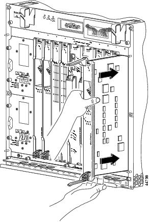
Figure 17-17 Inserting the Carrier
Step 3
Step 4
Figure 17-18 Captive Screw Locations
Step 5
Warning
Installing a Half-Height Line Card Into a Carrier
Use the following procedure to install a half-height line card into an installed carrier. If you have not installed the carrier, see the "Installing the Half-Height Line Card Carrier" section to install the carrier in the chassis, before beginning the instructions in this section.
If you plan to replace a half-height line card, see the "Removing a Half-Height Line Card" section before you begin this procedure.
Step 1
Figure 17-19 ESD Chassis Connection—Cisco 10008 Router
Caution
Step 2
Figure 17-20 Inserting the Line Card
Step 3
Step 4
Step 5
Figure 17-21 Closing the Ejector Levers
The line card cycles through its power-on self-test (POST). The Fail LED lights during portions of the POST, but remains off after POST on a properly working line card. If the Fail LED remains on, go to Chapter 18, "Troubleshooting the Installation."
Step 6
Figure 17-22 Captive Screw Locations
Caution
Warning
Warning
Depending on which half-height line card you have installed, go to one of the following sections:
•
Installing SFP Modules or GBIC Modules
We recommend inspecting and cleaning optics before installation. See the Inspection and Cleaning Procedures for Fiber-Optic Connections document and the Compressed Air Cleaning Issues for Fiber-Optic Connections for more information on cleaning optical devices.
The following information is in this section:
•
•
Guidelines for Using SFP Modules or GBIC Modules
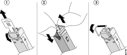
SFP modules from different manufacturers provide different methods for freeing the locking pin and removing the SFP module. Figure 17-23 shows three module types.
Figure 17-23 Types of SFP Module Latches
•
–
–
–
•
•
•
•
Installing an SFP Module or GBIC Module
Warning
Warning
Warning
Warning
Your line card may ship with an SFP module installed. Use the procedures in this section if you need to install or change the SFP module.
Use only SFP modules supplied by Cisco with your line card. Each SFP module contains an internal serial EEPROM that is security-programmed by the SFP manufacturer with information that provides a way for Cisco (through Cisco IOS software) to identify and validate the SFP module as a module type that is tested and qualified by Cisco to operate properly with your line card. Unapproved SFP modules (those not purchased directly from Cisco) do not work with the line card.
Installing an SFP Module
This section describes the procedure to insert an SFP module into the Gigabit Ethernet half-height line card.
Step 1
Figure 17-24 ESD Chassis Connection—Cisco 10008 Router
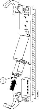
Step 2
Figure 17-25 Inserting the SFP Module
Step 3
Go to the "Attaching Cables" section.
Installing a GBIC Module
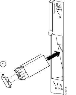
Figure 17-26 and Figure 17-27 show how to install a GBIC module:
Figure 17-26 ESD Chassis Connection—Cisco 10008 Router
Step 1
Step 2
Step 3
Note
Figure 17-27 Installing a GBIC Module
Step 4
Caution
This completes the procedure for installing a GBIC module.
Proceed to the "Attaching Cables" section to attach the SC-type fiber-optic cable to the GBIC module.
Attaching Cables
This section contains the following information:
•
•
•
•
Attaching Multimode and Single-Mode Optical Fiber Cables
Before attaching optical fiber cables, we recommend that you first clean them. Attaching dirty fiber- optic cables to a line card may result in the line card appearing to not function.
For information about cleaning fiber-optic cable connectors and receptacles, see the Inspection and Cleaning Procedures for Fiber-Optic Connections document and the Compressed Air Cleaning Issues for Fiber-Optic Connections for more information on cleaning optical devices.
It provides detailed illustrations and photos of procedures and equipment required to properly clean fiber-optic connections.
Both simplex (Figure 17-28) and duplex SC- (Figure 17-29) and LC-type (Figure 17-30, Figure 17-31) connectors are described in this section.
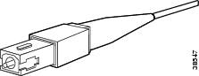
Figure 17-28 Simplex SC-Type Cable and Connector
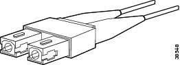
Figure 17-29 Duplex SC-Type Cable and Connector
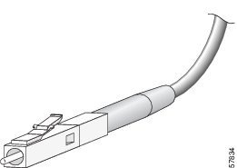
Figure 17-30 Simplex LC-Type Cable and Connector
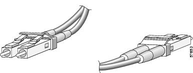
Figure 17-31 Duplex LC-Type Cable and Connector
Attach the appropriate optical fiber cable directly to the SC-type receptacle on the GBIC module, the LC-type connector on the SFP module, or the LC- or SC-type connector on the line card. You can use either simplex or duplex connectors for most devices.
•
•
Note
Note
Warning
Warning
Caution
Step 1
Step 2
Figure 17-32 Connecting an Optical Fiber Cable
Step 3
Figure 17-33 Optical Fiber Cable Management
Go to the "Checking the Installation" section.
Attaching RJ-45 Ethernet Cables
Use this section for information on attaching Ethernet cables to the RJ-45 ports on line cards and copper SFP modules.
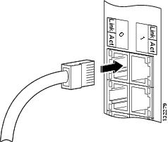
Step 1
Figure 17-34 Attaching Ethernet Cables
Step 2
Attaching the 24-Port Channelized E1/T1 Line Card Adapter Cable
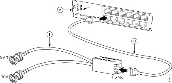
An RJ-45 STP cable with two male RJ-45 connectors is required to connect the adapter cable and RJ-45 ports on the face of the line card (Figure 17-35).
Figure 17-35 75-120 Ohm Adapter Cable
Cisco cable adapters (CAB-ADAPT-75-120) connect 75-ohm unbalanced G.703 E1 coaxial BNC transmit and receive lines to Cisco E1 120-ohm balanced transmit and receive lines
To attach the adapter cable for the 24-port channelized E1/T1 line card, follow these instructions:
Step 1
Figure 17-36 Attaching the RJ-45 Port STP Cable to the Adapter Cable
Step 2
Go to the "Checking the Installation" section.
Attaching Coaxial Cables
If your line card uses the BNC connectors on the rear of the router, attach the cables as noted in the specific line card overview chapter.
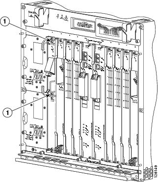
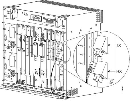
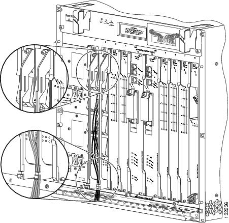
Figure 17-37 shows an overview of the BNC connectors on the rear of the chassis.
Figure 17-37 Identifying the BNC Connectors and Half-Height Card Subslots—Cisco 10008 Router
Line card slot 8
Line card slot 1
Line cards slot 5
Power supply
Blower module
Half-height line card subslot 0
Line card slot 4
Half-height line card subslot 1
Figure 17-38 shows BNC connectors and card subslots.
Figure 17-38 Identifying the BNC Connectors and Half-Height Card Subslots—Cisco 10005 Router
Line card slots 1 (top) to 5 (bottom)
Subslots 1/0 (top) to 5/0 (bottom)
Subslots 1/1 (top) to 5/1 (bottom)
Go to the "Checking the Installation" section.
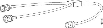
Attaching the 4-Port Channelized T3 Half-Height Line Card Optional Y-Cables
The Y-cables described in this section are only for the 4-port channelized T3 half-height line card, and are only used when configuring redundancy. The optional Y-Cable product number is CAB-BNC-71NY=.
Caution
Caution
Use the following information when preparing to install the Y-cables (Figure 17-39):
•
•
•
•
•
Caution
Figure 17-39 Optional Y-Cable
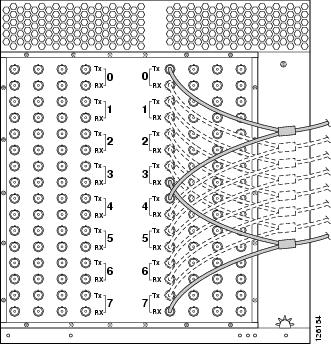
Figure 17-40 shows the optional connections.
Figure 17-40 Optional Y-Cable Connections
The optional Y-cables can be used to provide one-to-one line card redundancy. For Y-cable redundant applications, see the "Configuration Summary" section, and configure the hardware as follows:
•
•
•
–
–
–
Configuration Summary
Caution
1.
a.
b.
c.
2.
a.
b.
c.
3.
a.
b.
See the Cisco 10000 Series Routers Line Card Configuration Guide for information about configuring redundancy using the optional Y-cables.
Go to "Checking the Installation" section.
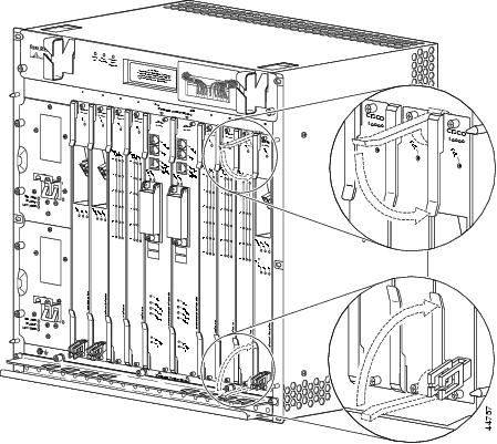
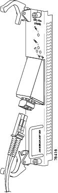
Using the Cable-Management Bracket
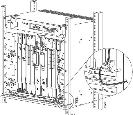
After attaching the appropriate cables, thread the cables through the cable-management brackets attached to full-sized line cards (Figure 17-41). Half-height line cards do not have cable-management brackets.
Figure 17-41 Using the Cable-Management Bracket
Use the Velcro strap at the bottom of the cable-management bracket to gather and tie the cables together.
Removing an SFP Module or GBIC Module
Use the following procedure to remove an SFP module or GBIC module from a line card.
Note
Step 1
Figure 17-42 ESD Chassis Connection
Note
Step 2
Figure 17-43 Disconnecting the LC-Type Optical Fiber Cable
Figure 17-44 Removing a Tab-Type SFP Module
Figure 17-44 and Figure 17-45 show SFP modules s with two different types of locking mechanisms being removed.
Step 3
•
Caution
Figure 17-45 Removing a Bale Clasp -Type SFP Module
•
Step 4
Warning
Warning
Step 5
Removing Full-Size Line Cards
Note
It is not necessary to remove the cables if you are not replacing the card. If you are removing a line card that uses BNC cables, and are replacing the same type of card in the same slot, you do not need to remove the coaxial cables. If you are removing a line card that uses coaxial cables, and are not replacing the same type of card in the same slot, you must remove the coaxial cables from the BNC connectors.Use the following procedure to remove a line card from the chassis:
Step 1
Figure 17-46 ESD Connection—Cisco 10008 Router
Figure 17-47 ESD Chassis Connection—Cisco 10005 Router
Note
Step 2
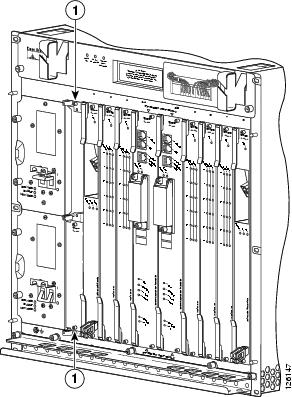
Figure 17-48 Captive Screw Locations
Step 3
Step 4
Figure 17-49 Opening the Ejector Levers
Step 5
If you are not installing a replacement line card, install a blank faceplate in the slot.
Warning
If you have a Cisco 10005 chassis, and a line card using BNC connectors, see Appendix A, "Cisco 10005 Extender Card Information" for information on removing the extender card.
Removing Half-Height Line Cards and Carrier
This section describes how to properly remove half-height line cards and the carrier from the chassis (for purposes of updating or upgrading to a new line card). This section includes the following tasks:
•
Removing a Half-Height Line Card
Note
You do need to remove the cables if you are not replacing the card. If you are removing a line card that uses BNC cables, and are replacing the same type of card in the same slot, you do not need to remove the coaxial cables. If you are removing a line card that uses coaxial cables, and are not replacing the same type of card in the same slot, you must remove the coaxial cables from the BNC connectors.
Step 1
Use the following procedure to remove a half-height line card from the chassis:
Figure 17-50 ESD Connection—Cisco 10008 Router
Figure 17-51 ESD Connection—Cisco 10005 Router
Note
Step 2
Step 3
Figure 17-52 Captive Screw Locations
Step 4
Figure 17-53 Opening the Ejector Levers
Step 5
Step 6
Caution
Warning
Removing a Carrier
Use the following procedure to remove a carrier from the chassis:
Warning
Step 1
Figure 17-54 ESD Chassis Connection
Note
Caution
Step 2
Step 3
Figure 17-55 Captive Screw Locations
Step 4
Step 5
Step 6
Figure 17-56 Removing the Carrier from the Chassis
Step 7
Warning
Checking the Installation
Refer to the overview section of each chapter for LED information.
This section describes the procedures you can use to verify the line card installation, and includes information on the following topics:
•
•
•
If you experience other problems that you are unable to solve, contact Cisco Technical Support (see the "Obtaining Documentation, Obtaining Support, and Security Guidelines" section on page -xix) or a service representative for assistance.
To configure the new interface, use the Cisco 10000 Series Router Line Card Configuration Guide.
Using show Commands to Verify Line Card Status
Note
The following procedure uses show commands to verify that the line card is configured and operating correctly.
Step 1
Step 2
Step 3
Step 4
Step 5
If the line card is down and you configured it as up, or if the displays indicate that the hardware is not functioning properly, ensure that the network interface is properly connected and terminated. If you still have problems bringing the line card up, contact a service representative for assistance.
Using show Commands to Display Line Card Information
Table 17-3 describes the show commands you can use to display line card information.
Note
Using the ping Command to Verify Network Connectivity
The ping command allows you to verify that a line card is functioning properly and to check the path between a specific port and connected devices at various locations on the network. After you verify that the system has booted successfully and is operational, you can use this command to verify the status of the line card ports. Refer to the publications listed in the "Related Documentation" section on page -xix for detailed command descriptions and examples.
Note
The ping command sends an echo request out to a remote device at an IP address that you specify. After sending a series of signals, the command waits a specified time for the remote device to echo the signals. Each returned signal is displayed as an exclamation point (!) on the console terminal; each signal that is not returned before the specified timeout is displayed as a period (.). A series of exclamation points (!!!!!) indicates a good connection; a series of periods (.....) or the messages [timed out] or [failed] indicate that the connection failed.
Following is an example of a successful ping command to a remote server with the IP address 10.1.1.60:
Router# ping 10.1.1.60 <Return>Type escape sequence to abort.Sending 5, 100-byte ICMP Echoes to 10.1.1.60, timeout is 2 seconds:!!!!!Success rate is 100 percent (5/5), round-trip min/avg/max = 1/15/64 msRouter#If the connection fails, verify that you have the correct IP address for the server and that the server is active (powered on), and repeat the ping command.
Configuring a Line Card
Preprovisioning a line card slot downloads software to the line card slot for the line card you are planning to install. Preprovisioning allows you to prepare in advance a complete configuration for the line card, including items you normally need to configure after initially configuring the line card, such as PVCs under an ATM line card or VLANs under an Ethernet line card.
Resetting a line card reloads line card software without having to manually insert and remove the line card.
After the line card is successfully installed, configure the card for network use. For information about configuring line cards, including information about preprovisioning the line card slot and resetting the line card, see the Cisco 10000 Series Router Line Card Configuration Guide.
Note