Feedback Feedback
|
Table Of Contents
1-Port Gigabit Ethernet Half-Height Line Card Overview
Software and Hardware Compatibility
Line Card, Router, and Processor Compatibility
SFP Module Configurations and Specifications
Mode-Conditioning Gigabit Ethernet Patch Cord Description
1-Port Gigabit Ethernet Half-Height Line Card Overview
This chapter describes the Cisco 10000 series 1-port Gigabit Ethernet half-height line card (referred to as the 1-port Gigabit Ethernet half-height line card), and contains the following sections:
•
Software and Hardware Compatibility
•
•
•
Line Card Summary
Table 10-1 1-Port Gigabit Ethernet Half-Height Line Card Summary
ESR-HH-1GE=
1-Port Gigabit Ethernet line card
Initial Cisco IOS releases for PRE-1:
12.0(23)S and later releases of Cisco IOS 12.0S
Initial Cisco IOS releases for PRE-2:
12.2(15)BX and later releases of Cisco IOS 12.2BX
12.2(28)SB and later releases of Cisco IOS Release 12.2SB
12.3(7)XI and later releases of Cisco IOS 12.3 XIInitial Cisco IOS releases for PRE-3:
12.2(31)SB2 and later releases of 12.2SB2
For registered Cisco.com users, use Software Advisor to determine the software releases for this line card.
ESR-HH-CARRIER=
Full-length base carrier for half-slot line card
—
ESR-HH-COVER=
Blank filler for half-height line cards
—
SFP-GE-T=
1000BASE-T pluggable transceiver for Category 5 copper wire
12.2(31)SB6 and later releases of Cisco IOS 12.2SB6
SFP-GE-S=
(previously GLC-SX-MM=)1000BASE-SX pluggable transceiver
—
SFP-GE-L=
(previously GLC-LH-SM=)1000BASE-LX pluggable transceiver
—
GLC-ZX-SM=
(previously ESR-SFP-ZX=)1000BASE-ZX pluggable transceiver
—
CWDM-SFP-1470
Longwave 1470 nm laser, single mode
Color: Gray12.2(28)SB1 and later releases of Cisco IOS 12.2SB
CWDM-SFP-1490
Longwave 1490 nm laser, single mode
Color: Violet12.2(28)SB1 and later releases of Cisco IOS 12.2SB
CWDM-SFP-1510
Longwave 1510 nm laser, single mode
Color Identifier: Blue12.2(28)SB1 and later releases of Cisco IOS 12.2SB
CWDM-SFP-1530
Longwave 1530 nm laser, single mode
Color Identifier: Green12.2(28)SB1 and later releases of Cisco IOS 12.2SB
CWDM-SFP-1550
Longwave 1550 nm laser, single mode
Color Identifier: Yellow12.2(28)SB1 and later releases of Cisco IOS 12.2SB
CWDM-SFP-1570
Longwave 1570 nm laser, single mode
Color Identifier: Orange12.2(28)SB1 and later releases of Cisco IOS 12.2SB
CWDM-SFP-1590
Longwave 1590 nm laser, single mode
Color Identifier: Red12.2(28)SB1 and later releases of Cisco IOS 12.2SB
CWDM-SFP-1610
Longwave 1610 nm laser, single mode
Color Identifier: Brown12.2(28)SB1 and later releases of Cisco IOS 12.2SB
The 1-port Gigabit Ethernet half-height line card:
•
•
Note
You install this line card in a Cisco 10000 chassis half-height slot carrier, which you must first install in the Cisco 10000 chassis slot. You can run this line card with a second line card in the other subslot.
The line card uses a small form-factor pluggable (SFP) module that supports a variety of Gigabit Ethernet interface types (SX, LX/LH, ZX, BASET, and CWDM), which you can change or upgrade at any time.
For more information about Coarse Wave Division Multiplexer (CWDM) Small Form-Factor Pluggable (SFP) laser optical transceiver modules, see the Cisco CWDM GBIC and CWDM SFP Installation Note at:
http://www.cisco.com/univercd/cc/td/doc/product/gbic_sfp/gbic_doc/78_15222.htm
Note
Note
If you are a registered Cisco.com user, see Feature Navigator for supported features.
Software and Hardware Compatibility
To check the minimum software requirements of Cisco IOS software for the hardware installed on your router, Cisco maintains the Software Advisor tool on Cisco.com. This tool does not verify whether line cards within a system are compatible, but provides the minimum Cisco IOS requirements for individual hardware line cards, modules, or options.
Note
To access Software Advisor, go to Cisco.com and click Login, type Software Advisor in the Search box, and click Go. Click the link for the Software Advisor tool.
Choose a product family or enter a specific product number to search for the minimum supported software release needed for your hardware.
Line Card, Router, and Processor Compatibility
Table 10-2 lists router model, line card, and processor compatibility.
Table 10-2 Line Card, Router, and Processor Compatibility
1-port Gigabit Ethernet half-height line card
Yes
Yes
Yes
Yes
Yes
No
1 Using the 1-port Gigabit Ethernet half-height line card with the PRE-1 is not recommended because of the bandwidth limitations on the PRE-1. Line rate speed in not achievable with the configuration of the 1-port Gigabit Ethernet half-height line card and PRE-1.
LEDs
The 1-port Gigabit Ethernet half-height line card LEDs are listed in Figure 10-1.
Figure 10-1 1-Port Gigabit Ethernet Half-Height Line Card Faceplate Description
Ejector levers
SFP module port (TX/RX)
FAIL LED
LINK LED
RX (receive) LED
TX (transmit) LED
Table 10-3 provides a description of the 1-port Gigabit Ethernet half-height line card LEDs.
Note
Physical Specifications
The 1-port Gigabit Ethernet half-height line card physical specifications appear in Table 10-4.
Slot Locations
The line card slot designations are shown in this section. Figure 10-2 shows line card slot designations for the Cisco 10008 router and Figure 10-3 shows line card slot designations for the Cisco 10005 router.
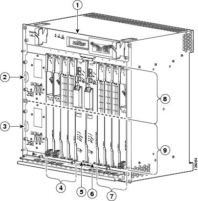
Figure 10-2 Line Card Slot and Subslot Designations for the Cisco 10008 Router
Blower module
PRE slot B
Primary PEM
Line card slots 5 to 8
Redundant PEM
Subslot 0
Line card slots 1 to 4
Subslot 1
PRE slot A
The 1-port Gigabit Ethernet half-height line card can be installed in subslot 0 or subslot 1 of the line card slot 1 through slot 8. The Cisco 10000 Carrier is used with the 1-Port Gigabit Ethernet Half Height line card.
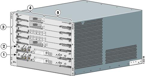
Figure 10-3 Line Card Slot and Subslot Designations for the Cisco 10005 Router
PRE slot A
Subslots 1/0 (top) to 5/0 (bottom)
PRE slot B
Subslots 1/1 (top) to 5/1 (bottom)
Line card slots 1 (top) to 5 (bottom)
The 1-port Gigabit Ethernet half-height line card can be installed in any subslot in line card slot 1 through slot 5. The Cisco 10000 Carrier is used with the 1-port Gigabit Ethernet half-height line card.
Cables and Connectors
The 1-port Gigabit Ethernet half-height line card supports single Ethernet interfaces based on SFP technology. The following SFP modules are supported by this line card:
•
•
•
•
The Coarse Wave Division Multiplexer (CWDM) Small Form-Factor Pluggables (SFPs) are hot-swappable, laser optical transceiver modules. You can plug these SFPs into standard receptacles in Cisco routers and switches to convert Gigabit Ethernet electrical signals into a single-mode fiber-optic (SMF) interface. The router supports the following CWDM SFPs:
•
•
•
•
•
•
•
•
You can connect the CWDM SFPs to CWDM passive optical system optical add/drop multiplexer (OADM) or multiplexer/demultiplexer plug-in modules using single-mode fiber-optic cables with standard LC connectors. For more information, see the Cisco CWDM GBIC and CWDM SFP Installation Note at the following URL:
http://www.cisco.com/univercd/cc/td/doc/product/gbic_sfp/gbic_doc/78_15222.htm
When shorter distances of single-mode fiber are used, it may be necessary to insert an inline optical attenuator in the link to avoid overloading the receiver. A 5-decibel (dB) or 10-dB inline optical attenuator should be inserted between the fiber-optic cable plant and the receiving port on the GLC-ZX-SM= at each end of the link whenever the fiber-optic cable span is less than 25 km. CWDM SFPs require a minimum of 12-dB optical attenuation. If the fiber itself is not providing the attenuation, then an attenuator device is required.
Note
Use these guidelines for installing SFP modules:
•
•
•
•
SFP Module Configurations and Specifications
Table 10-5 lists the SFP configurations.
Table 10-5 SFP Configurations
SFP-GE-S=
Short wavelength (1000BASE-SX)
SFP-GE-L=
Long wavelength/long haul (1000BASE-LX)
SFP-GE-T=
RJ-45 copper SFP module (1000BASE-T)
Table 10-6 lists the SFP physical specifications.
Table 10-7 lists the SFP port cabling specifications.
Table 10-7 SFP Port Cabling Specifications
1000BASE-T
SFP-GE-T=N/A
Copper
N/A
N/A
328 ft. (100 m)
1000BASE-SX
SFP-GE-S=
(previously GLC-SX-MM=)850
MMF
62.5
62.5
50.0
50.0160
200
400
500722 ft (220 m)
902 ft (275 m)
1640 ft (500 m)
1804 ft (550 m)1000BASE-LX/LH
SFP-GE-L=
(previously GLC-LH-SM=)1300
MMF1
SMF62.5
50.0
50.0
9/10500
400
500
—1804 ft (550 m)
1804 ft (550 m)
1804 ft (550 m)
6.2 miles (10 km)1000BASE-ZX
GLC-ZX-SM=)1550
SMF
9/10
—
43.5 miles (70 km)
SMF2
8
—
62.1 miles
(100 km)CWDM-SFP-####=
1470 through 1610
SMF
—
—
—
1 A mode-conditioning patch cord is required. Using an ordinary patch cord with MMF, 1000BASE-LX/LH SFP modules, and a short link distance (tens s of meters) can cause transceiver saturation resulting in an elevated bit error rate (BER). In addition, when using the LX/LH SFP module with 62.5-micron diameter MMF, you must install a mode-conditioning patch cord between the SFP module and the MMF cable on both the transmit and receive ends of the link. The mode-conditioning patch cord is required for link distances greater than 984 ft (300 m).
2 Dispersion-shifted single-mode fiber-optic cable.
Table 10-8 provides SFP module power budget information.
Table 10-8 Gigabit Ethernet SFP Transmit Power, Receive Power, and Power Budget
SFP-GE-S=
-9.5 dBm1
-4 dBm1
-17 dBm
0 dBm
7.5 dBm2
SFP-GE-L=
-9.5 dBm3
-11.5dBm4
-3 dBm5
-20 dBm
-3 dBm
GLC-ZX-SM=
0 dBm
5 dBm
-23 dBm
0 dBm
-24 dBm
CWDM-SFP-####=
0 dBm
5 dBm
-28 dBm
-7 dBm
28 dB
1 For fiber types 50/125 mm, NA = 0.20 fiber and 62.5/125 mm, NA = 0.275 fiber.
2 For fiber types 50/125 mm MMF and 62.5/125 mm MMF.
3 For fiber types 9/125 mm SMF.
4 For fiber types 62.5/125 mm MMF and 50/125 mm MMF.
5 For fiber types 9/125 mm SMF, 62.5/125 mm MMF, and 50/125 mm MMF.
6 For fiber types 50/125 mm MMF and 62.5/125 mm MMF.
7 For fiber type 10 mm SMF.
Related Documentation
For related documentation on SFP modules, see the following publications:
•
•
Mode-Conditioning Gigabit Ethernet Patch Cord Description
A mode-conditioning patch cord can be used with the SFP-GE-L= (SFP module) to allow reliable laser transmission between the single-mode laser source on the SFP module and a multimode optical fiber cable.
When an unconditioned laser source designed for operation on single-mode optical fiber is directly coupled to a multimode optical fiber cable, an effect known as differential mode delay (DMD) might result in a degradation of the modal bandwidth of the optical fiber cable.
This degradation results in a decrease in the link span (the distance between a transmitter and a receiver) that can be supported reliably. The effect of DMD can be overcome by conditioning the launch characteristics of a laser source. A practical means of performing this conditioning is to use a device called a mode-conditioning patch cord.
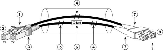
A mode-conditioning patch cord is an optical fiber cable assembly that consists of a pair of optical fibers terminated with connector hardware. Specifically, the mode-conditioning patch cord is composed of a single-mode optical fiber permanently coupled off-center (see Offset in Figure 10-4) to a graded-index multimode optical fiber. Figure 10-4 shows a diagram of the mode-conditioning patch cord assembly.
Figure 10-4 Mode-Conditioning Patch Cord Assembly for an SFP Module
Gray color identifier
Single-mode bar
To Gigabit Ethernet interface
Offset
Blue color identifier
Beige color identifier
Multimode bar
To cable plant
The mode-conditioning patch cord assembly is composed of duplex optical fibers, including a single-mode-to-multimode offset launch fiber connected to the transmitter, and a second conventional graded-index multimode optical fiber connected to the receiver. The use of a plug-to-plug patch cord maximizes the power budget of multimode 1000BASE-LX and 1000BASE-LH links.
The mode-conditioning patch cord is required to comply with IEEE standards. The IEEE found that link distances could not be met with certain types of fiber-optic cable cores. The solution is to launch light from the laser at a precise offset from the center, which is accomplished by using the mode-conditioning patch cord. At the output of the patch cord, the SFP-GE-L= is compliant with the IEEE 802.3z standard for 1000BASE-LX.
Go to Chapter 16, "Preparing for Installation" to begin the installation or replacement of the line card. For troubleshooting information, see Chapter 18, "Troubleshooting the Installation."