Feedback Feedback
|
Table Of Contents
1-Port Gigabit Ethernet Line Card Overview
Software and Hardware Compatibility
Line Card, Router, and Processor Compatibility
Specifications for the Gigabit Ethernet GBIC Module
Mode-Conditioning Gigabit Ethernet Patch Cord Description
1-Port Gigabit Ethernet Line Card Overview
This chapter describes the Cisco 10000 series 1-port Gigabit Ethernet line card (referred to as the 1-port Gigabit Ethernet line card), and contains the following sections:
•
Software and Hardware Compatibility
•
•
Line Card Summary
Table 11-1 1-Port Gigabit Ethernet Line Card Summary
ESR-1GE=
1-port Gigabit Ethernet line card
Initial Cisco IOS releases for PRE-1:
12.0(22)S and later releases of Cisco IOS 12.0S
Initial Cisco IOS releases for PRE-2:
12.3(7)XI and later releases of Cisco IOS Release 12.3X
12.0(22)S and later releases of Cisco IOS 12.0S
12.2(28)SB and later releases of Cisco IOS Release 12.2(28)SBInitial Cisco IOS releases for PRE-3:
12.2(31)SB2 and later releases of Cisco IOS Release 12.2SB2
For registered Cisco.com users, use Software Advisor to determine the software releases for this line card.
WS-G5484=
1000BASE-SX GBIC
—
WS-G5486=
1000BASE-LX/LH GBIC
—
WS-G5487=
1000BASE-ZX GBIC
—
The 1-port Gigabit Ethernet line card provides:
•
•
The Cisco 10000 system supports multiple Gigabit Ethernet line cards to support connectivity to multiple destinations and for redundant and fault-tolerant configurations.
The port uses a Gigabit Interface Converter (GBIC) that supports Gigabit Ethernet rates on a variety of Gigabit Ethernet interface types (SX, LH/LX, ZX) which you can change or upgrade at any time (see Table 11-5).
If you are a registered Cisco.com user, see Feature Navigator for supported features.
Software and Hardware Compatibility
To check the minimum software requirements of Cisco IOS software with the hardware installed on your router, Cisco maintains the Software Advisor tool on Cisco.com. This tool does not verify whether line cards within a system are compatible, but does provide the minimum Cisco IOS requirements for individual hardware line cards, modules, or options.
Note
To access Software Advisor, click Login at Cisco.com, type Software Advisor in the SEARCH box, and click Go. Click the link for the Software Advisor tool.
Choose a product family or enter a specific product number to search for the minimum supported software release needed for your hardware.
Line Card, Router, and Processor Compatibility
Table 11-2 lists router model, line card, and processor compatibility.
Table 11-2 Line Card, Router, and Processor Compatibility
1-port Gigabit Ethernet line card
Yes
Yes
Yes
Yes
Yes
No
Note
LEDs
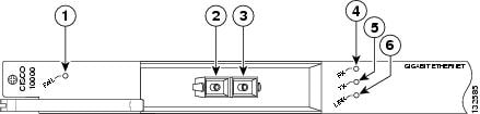
The 1-port Gigabit Ethernet line card LEDs are shown in Figure 11-1.
Figure 11-1 1-Port Gigabit Ethernet Line Card Faceplate Description
Table 11-3 provides a description of the 1-port Gigabit Ethernet line card LEDs.
Physical Specifications
The 1-port Gigabit Ethernet line card physical specifications are shown in Table 11-4.
Slot Locations
The line card slot designations are shown in this section. See Figure 11-2 for line card slot designations for the Cisco 10008 router and Figure 11-3 for line card slot designations for the Cisco 10005 router.
Figure 11-2 Line Card Slot Designations for the Cisco 10008 Router
Blower module
PRE slot 0A
Primary PEM
PRE slot 0B
Redundant PEM
Line card slots 5 to 8
Line card slots 1 to 4
The 1-port Gigabit Ethernet line card can be installed in line card slot 1 through slot 8.
Figure 11-3 Line Card Slot Designations for the Cisco 10005 Router
The 1-port Gigabit Ethernet line card can be installed in line card slot 1 through slot 5.
Cables and Connectors
Table 11-5 lists the 1-port Gigabit Ethernet line card GBIC modules and their respective cable types and lengths.
Use these guidelines for installing GBIC modules:
•
•
•
•
Table 11-5 GBIC Port Cabling Specifications
1000BASE-SX
WS-G5484 (previously ESR-GBIC-SX)850
MMF
62.5
62.5
50.0
50.0160
200
400
500722 ft (220 m)
902 ft (275 m)
1640 ft (500 m)
1804 ft (550 m)1000BASE-LX/LH
WS-G5486 (previously ESR-GBIC-LHLX)1300
MMF1
SMF62.5
50.0
50.0
8 to 10500
400
500
—1804 ft (550 m)
1804 ft (550 m)
1804 ft (550 m)
6.2 miles (10 km)1000BASE-ZX
WS-G5487 (previously
ESR-GBIC-ZX)1550
SMF
Not Conditional
—
43.5 mi (70 km) to
62 mi (100 km)2
1 Mode-conditioning patch cord (CAB-GELX-625 or equivalent) is required. If you use an ordinary patch cord with MMF, 1000BASE-LX/LH GBICs, and a short link distance (tens of meters), this can cause transceiver saturation, resulting in an elevated bit error rate (BER). In addition, when you use the LX/LH GBIC with 62.5-micron diameter MMF, you must install a mode-conditioning patch cord between the GBIC and the MMF cable on both the transmit and receive ends of the link. The mode-conditioning patch cord is required for link distances greater than 984 ft (300 m).
2 100 km over premium single-mode fiber or dispersion shifted single-mode fiber.
Specifications for the Gigabit Ethernet GBIC Module
Table 11-6 lists the GBIC module physical specifications.
Table 11-7 provides the optical power budget for the 1-port Gigabit Ethernet line card.
Table 11-7 Gigabit Ethernet GBIC Transmit Power, Receive Power, and Power Budget
10000BASE-SX
WS-G5484-9.5 dBm1
-4 dBm1
-17 dBm
0 dBm
7.5 dBm2
1000BASE-LX/LH
WS-G5486(SMF) -9.5 dBm3
(MMF) -11.5dBm4
-3 dBm5
-19 dBm
-3 dBm
(SMF) 9.5 dBm4
(MMF) 7.5 dBm3
1000BASE-ZX
WS-G54870 dBm
5 dBm
-23 dBm
-3 dBm
-23 dBm
1 For fiber types 50/125 mm, NA = 0.20 fiber and 62.5/125 mm, NA = 0.275 fiber.
2 For fiber types 50/125 mm MMF and 62.5/125 mm MMF.
3 For fiber types 9/125 mm SMF.
4 For fiber types 62.5/125 mm MMF and 50/125 mm MMF.
5 For fiber types 9/125 mm SMF, 62.5/125 mm MMF, and 50/125 mm MMF.
Mode-Conditioning Gigabit Ethernet Patch Cord Description
A mode-conditioning patch cord can be used with the WS-G5486 (GBIC module) to allow reliable laser transmission between the single-mode laser source on the GBIC module and a multimode optical fiber cable.
When an unconditioned laser source designed for operation on single-mode optical fiber is directly coupled to a multimode optical fiber cable, an effect known as differential mode delay (DMD) might result in a degradation of the modal bandwidth of the optical fiber cable.
This degradation results in a decrease in the link span (the distance between a transmitter and a receiver) that can be supported reliably. The effect of DMD can be overcome by conditioning the launch characteristics of a laser source. A practical means of performing this conditioning is to use a device called a mode-conditioning patch cord.
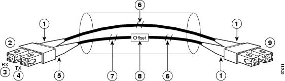
A mode-conditioning patch cord is an optical fiber cable assembly that consists of a pair of optical fibers terminated with connector hardware. Specifically, the mode-conditioning patch cord is composed of a single-mode optical fiber permanently coupled off-center (see Offset in Figure 11-4) to a graded-index multimode optical fiber. Figure 11-4 shows a diagram of the mode-conditioning patch cord assembly.
Figure 11-4 Mode-Conditioning Patch Cord Assembly for a GBIC Module
Beige color identifier
Multimode fiber
To Gigabit Ethernet interface
Single-mode fiber
RX
Offset
TX
To cable plant
Blue color identifier
Go to Chapter 16, "Preparing for Installation" to begin the installation or replacement of the line card.
For troubleshooting information, see Chapter 18, "Troubleshooting the Installation."