Downloads |
 Feedback Feedback
|
Table Of Contents
NEMServer/Backup Server Properties
Downloading to Multiple Devices
Uploading from Multiple Devices
Generating a Configuration Report
Unconnected WAN Interfaces Report
Managing Network Elements
Overview of Network Elements
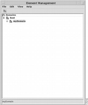
In the GUI application developed by Cisco, network elements and the domains to which they belong are managed through the Element Management window. To open this window, start the GUI application and click on the Element Management button on the Services control panel. The window displays all of the elements, domains, and subdomains to which you have access (as determined by the permissions group to which you belong).
From this window, you can create, modify, or delete domains and network elements; check the status of elements; upload configurations from the devices to your database; download configurations from your database to devices; and initiate checks (check the validity of connections, for example) on configurations.
You can also import network elements into domains from a text file, using a command line script.
Element Management Window
The Element Management window displays devices and domains in an expandable tree structure. The root entry under the heading Domains is reserved for system use. Do not add elements to the root level. The system administrator (login admin) should create a user root domain. For more information about the root domain, see "Root Domain" in the chapter "." Also see the chapter "."
The top level in the data tree is the highest-level domain that you have permission to view. See the chapter "" for more information about permission groups.
Figure 4-1 Element Management window
The Element Management window contains the following menus:
File Menu
The File menu contains the following commands:
•
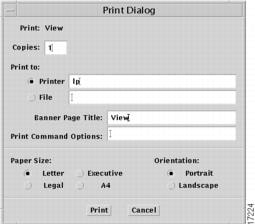
Print—sends a Postscript image of the Element Management window to the specified Postscript-enabled printer or to a Postscript file.
Figure 4-2 Print Dialog
Enter the number of copies you want printed in the Copies field. Select either the Printer or File button, and enter your printer's name in the Printer field or the filename you want the image saved as, in the Printer or File text box. (Files will be saved in the GUI/java/login subdirectory unless you specify a different path.) Enter a string in the Banner Page Title text box if you want to provide a title that will be printed on the banner page when you send the job to the printer. You can also provide a UNIX command-line option in the Print Command Option box. This dialog also allows you to choose paper size and orientation.
•
•
Edit Menu
The Edit menu contains the following command:
•
View Menu
The View menu contains the following commands:
•
•
•
Help menu
The Help menu contains the following command:
•
Creating Domains
Every domain you create will be a child of some other domain. To be able to create a domain, you must belong to a permissions group that has been granted create permission in the parent domain.
To create a new domain, right-click on the parent domain and choose the New option from the floating menu that opens, then choose the SubDomain command from the submenu. Enter a domain name in the dialog that opens and click the OK button (or click the Cancel button to close the dialog without adding a new subdomain).
Name Restrictions
Any name that is stored in the database (domain, element, template, template data, user, or permission group) can consist of any combination of alphanumeric characters (letters can be either upper or lower case) plus the underscore character, hyphen, and a period. Names cannot contain leading, trailing, or embedded spaces.
Domain Properties
When you click the New command on the floating options menu for a selected domain, the Domain Properties dialog will open.
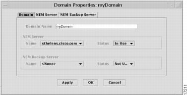
Figure 4-3 Domain Properties dialog—Domain tab
This dialog has three tabbed pages. When it opens, the Domain page is displayed.
The Domain Name field displays the name you gave the domain in the previous dialog. This is a read-only field. Once a domain has been created, you cannot change its name, except by deleting the domain from the Element Manager window and creating a new one.
The tab also contains fields for primary and secondary NEMServers. The NEM Server and NEM Backup Server group Name fields are both drop-down lists containing the names of all NEMServers currently registered with the Orbix Naming Service (launched as NS when the Cisco IP Manager servers were started). For information about NEMervers, see the section "NEMServer (Network Element Manager)" in the appendix "."
Select a server from the NEM Server list (set to <none> when the properties window opens for the first time) and choose In Use from its Status list.
If you have multiple NEMServers running and you want to select a backup that will automatically be put into service if the primary server becomes unavailable, select a second server from the NEM Backup Server list. Choose In Use from its Status list.
Click the Apply button at the bottom of the window. The status fields will be adjusted to reflect the actual status of the two servers. If both are up and available, the primary server's status will remain set to In Use and the backup server's status will be changed to Standby. If one of the servers is not up at the time, its status will be changed to Down and the other server will be the In Use server.
Once you have set the status and clicked the Apply button, you cannot manually change the status of a server. The only way to force a change in status is to shut one of the servers down and restart it.
Whenever a server that has been designated either the primary or backup NEMServer goes down, its status will be changed to Down. When the server becomes available again and there is another NEMServer in use, the status of the newly available server will be set to Standby.
For example, assume you have designated the server hostOne to be your primary NEMServer and the server hostTwo to be the backup. If hostOne goes down, hostTwo will automatically become the primary server (even though it will continue to be shown in the NEM Backup Server field in the properties window). The server hostTwo will remain the primary NEMServer until it is brought down.
This change in status will not be known to the GUI application until you close and reopen the Dialog Properties window.
NEMServer/Backup Server Properties
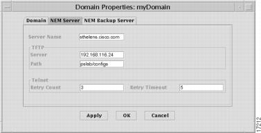
After selecting a server from the NEM Server drop-down list, select the NEM Server tab in the Domain Properties dialog to display information about that server.
Figure 4-4 Domain Properties dialog—NEM Server Tab
The NEM Server and NEM Backup Server pages are for information only. You cannot change any of the values displayed. (These two pages are identical, except for the values displayed in the fields.)
The pages show the servers' names, the TFTP hosts and subdirectories (relative to /tftpboot—if /tftpboot is designated as your TFTP subdirectory, this field will be empty), and the Telnet retry count and timeout values. TFTP hosts and subdirectories were specified during installation of the NEMServer package. Values for the Telnet Retry Count and Retry Timeout fields were set by server flags when the NEMServers were launched. For information on how to change any of these values, see the section "Changing Environment Variables and Server Launch Flags" in the chapter "."
Saving Properties
When you have selected the desired servers, click the Apply button to apply the properties to the domain and leave the Domain Properties window open, or click the OK button to apply the properties and close the window.
Creating Network Elements
To create a network element, you must belong to a permissions group that has been assigned create permissions for elements for the domain, on the Domain Resources tab in the AAS Manager window.
Right-click the mouse on a domain name in the data tree and select the New command, then select the Element command on the submenu that opens. Enter a name in the dialog that opens and click the OK button (or click the Cancel button to close the dialog without creating an element).
See the section "Name Restrictions" elsewhere in this chapter for limitations on characters in names.
The device will be added to the data tree displayed in the Element Management window. If it does not appear, you may have to choose the Refresh command on the View menu.
Note
If the Element Management window fails to display previously created elements in the data tree, right click on the domain, click on the Properties command in the floating menu that opens, and click the Apply or OK button in the Domain Properties window. (If the NEMServer status has changed to Down and then back to In Use, the GUI application code can sometimes fall out of synchronization with the actual state of the server as shown in the Domain Properties window.)
For information about NEMServer status, see the section "NEMServer/Backup Server Properties" elsewhere in this chapter.
Element Properties
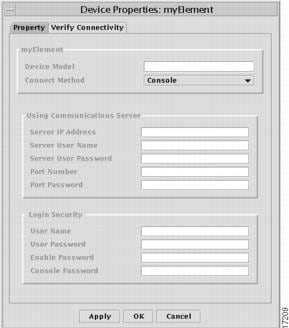
Right-click on the newly added device and select the Properties command from the menu that opens. The Device Properties dialog will be displayed, with the Property tab selected.
Figure 4-5 Device Properties dialog—Property tab (Console Connect Method)
This dialog is used to tell the Cisco IP Manager software what property values—IP addresses, usernames, passwords, and port numbers (depending on what is selected in the Connect Method list)—should be used when communicating with the selected device.
Property Tab
Select one of the following choices from the Connect Method drop-down list:
•
•
•
When you select a Connect Method, the Property page of the Device Properties window will change to display the properties that are appropriate to the type of connection.
Virtual Device Connect Method
The default selection is Virtual Device. The only property you can set for a virtual device is a text string designating the model of the device. The data entered in the Device Model field is for informational purposes, as a reminder whenever you check the device's properties. This data is not used elsewhere in the program.
VTY Connect Method
When you select VTY from the Connect Method drop-down list, the Property tab displays the following control groups and fields:
The Using VTY to Access Device control group contains a single field:
•
The Login Security control group contains the following fields:
•
•
•
Console Connect Method
When you select Console from the Connect Method drop-down list, the Property tab displays the following control groups and fields:
The Using Communications Server control group contains the following fields:
•
•
•
•
•
The Login Security control group contains the following fields:
•
•
•
•
When you have set the properties, click the Apply button to save the data to the database but keep the Device Properties dialog open. Click the OK button to save the data to the database and close the window. Or, click the Cancel button to close the window without saving the changes you have made in the dialog.
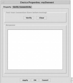
Verify Connectivity Tab
Once you have set the properties and saved them (by choosing the Save button at the bottom of the window), select the Verify Connectivity tab of the Device Properties window to test the properties. This will also verify the TFTP server communications, if you are using it.
Figure 4-6 Verify Connectivity dialog—Property tab
Click the Verify button to initiate a connection with the device.
The results will be displayed in the Response window. Use the Clear button to clear text from this window.
If the connection cannot be established (incorrect console password or IP address, for example), you will receive a general error message.
If the connection can be established but there is an error in the device properties, you will receive a more specific error message.
Editing Device Properties
To change the properties of a network element, right click on the device name in the data tree and select the Properties command from the floating menu that opens. Change the fields as desired and close the Device Properties dialog.
Importing Elements By Script
You can use the command-line utility importElement to add new elements that are defined in a text file. This script is located in the SRVRS/import subdirectory of your Cisco IP Manager installation.
Identify elements by entering the device's properties into the text file in the following order:
•
•
•
•
•
•
•
•
•
•
•
•
•
•
•
If a required property is omitted, the element will be skipped.
Use commas to separate variables, and new line characters to separate elements. You can leave fields empty, but there must be a comma for each. Empty lines and lines beginning with the # character will be ignored.
The following text file would add a virtual device called element_1, another device called element_2 which lists VTY as the connect method, and a device called element_3 which lists console as the connect method, to the domain myDomain:
element_1,myDomain,,Virtual Device,,,,,,,,,,,element_2,myDomain,,VTY, 1.2.3.4, cisco, sesame,,,,,,,,element_2.cfgelement_3,myDomain,,Console,,,,,1.2.3.4,comm_srvr_user_id,comm_srvr_password,1,port_password,consol_password,/tmp/element_3.cfgThe importElement utility takes a Cisco IP Manager username and the name of the import file as arguments. If the user's login name is ipmgr_user and the elements are listed in a text file called elements that is in the same directory as the importElement utility, then launch the script by entering the following on the command line:
./importElement ipmgr_user elementsThe domain myDomain must already exist in the Cisco IP Manager database, and the person launching the script (the user identified by ipmgr_user) must be a valid Cisco IP Manager user with permission to create elements in the domain myDomain.
If you are importing a large number of devices with this script, you should close all instances of the GUI application. As each device is added, the Cisco IP Manager servers will attempt to update any GUI application that is open. This can consume significant resources and, if the number of devices is very large, the GUI could experience a significant event interruption.
Working Config
To view the device's working config, right click on the device name and select the Working Config command from the menu that appears. For a description of a working config, see the section "Working Config versus Running Config" in the chapter "."
The Working Config window will open, with the text of the working config displayed.
Working configs can be created or modified in any of three ways:
•
•
•
If you choose the Import button at the bottom of configuration File window, an Element Download window will open.
Working with Devices
Once a network element exists in a domain and you have created a working config, you can use the floating options menu that opens when you right click the mouse to manage the uploading and downloading of configurations. This can be done either from/to individual devices or from/to multiple devices.
Note
Downloading to a Device
To transmit an existing working config to the device, right click on the device name in the data tree and choose the Download to Element command from the menu that opens.
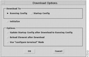
The Download Options window will open.
Figure 4-7 Download Options window
Choose the destination of the download operation by clicking either the Running Config or Startup Config button in the Download To control group. Other options on the dialog will be enabled or disabled according to your Download To selection.
If you are configuring a new router for the first time, select the Initialize checkbox (the Console connect method in the Element Properties dialog must also be selected). You can initialize a device only when the Running Config download option is selected; the checkbox will be disabled if you are downloading to the Startup Config.If you check the Initialize option, the Use "configure terminal" Mode option will automatically be checked and the option disabled. You cannot uncheck this option if you are initializing a device.
Download to Running Config
Select any combination of the following checkboxes in the Options group:
•
•
•
Download to Startup Config
When you are downloading to the startup config, only the following option is available:
•
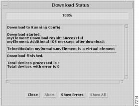
When you have made your selections, click the OK button to download the working configuration to the device. The Download Status window will open.
Figure 4-8 Download Status window
Click the Show Errors button to filter out positive responses from the messages displayed. This will allow you to focus on problems that need to be resolved. (Not everything will be filtered out of the response window; there will still be start, stop, and summary messages about the download operation.)
The Show All button reverts to the full display.
Be sure to read all messages completely. Text could have been generated by the Cisco IP Manager GUI application or NEMServer, the IOS parser, or by the device itself. Sometimes, adjacent messages may appear to contradict each other.
In the following example, it appears at first glance that the Reload operation succeeded, but further analysis shows that it did not.
In the first part of the status report, the Cisco IP Manager GUI application reports that the NEMServer has successfully issued the IOS command Reload. This is followed by the subsequent information that the router has returned the message "The date and time must be set first." This is a fatal error, and the Cisco IP Manager adds the information that, though the command was successfully issued, the operation failed.
pslab-2505: Reload successful.pslab-2505: Additional IOS message after reload:--------------------------------------------------IOS Reload command succeeded, but reload operation failed:"The date and time must be set first"--------------------------------------------------Reload finished.The message concludes with the information from the NEMServer that the Reload attempt is finished.
You should read all messages carefully to determine whether an operation was successfully completed.
Downloading to Multiple Devices
You can download working configurations to multiple devices in the Element Management window. Select all of the devices you want to configure, then right click the mouse to open a floating options menu.
Select the Download to Elements command. The Download Options window described previously will open. When you click the OK button, the working configurations for the selected devices will be downloaded, with the results of each download operation recorded in the Download Status window.
You can halt the download process at any time, by choosing the Abort button at the bottom of this window. This will terminate the download after completing the operation in progress. You cannot stop a download operation for a single element.
The messages in the window will tell you whether the download operation succeeded or failed for each device.
Uploading from a Device
Right click on a device name and select Upload from Element from the menu that appears. The Upload Options window will open. Select either Running Config or Startup Config from the Upload From control group. Then select any combination of the following checkboxes:
•
•
•
When you have set the options as desired, click the OK button to upload the configuration.
The Upload Status window will open and a Telnet session initiated with the device. When the operation is completed, the status of the attempt to upload will be displayed in the window's message area. Other than the title in the title bar, this window is identical to the Download Status window.
Uploading from Multiple Devices
To upload configurations from multiple elements, select the elements from the data tree in the Element Management window and right click the mouse to open a floating options menu. Choose the Group Upload from Elements command to open the Upload Options window.
Reload Element
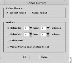
To force a reboot of the device, right click on a device name in the Element Management window's data tree and select the Reload Element option from the menu that opens. The Element Reload window will open.
Figure 4-9 Element Reload window
If you want to update the device's startup configuration from the working configuration, click the Update Startup Config checkbox before forcing the reload operation.
You can choose to reload after a specified interval of time (enter in the format specified in the dialog); at a specified time of the current day; or immediately, by choosing one of the following buttons:
•
•
•
Or, you can click the Cancel Reload button to cancel a previously set reload request.
Click the OK button to implement your selections.
Update Startup Config
To copy the device's running configuration into its startup configuration RAM, right click on a device name in the Element Management window's data tree. Select the Update Startup Config command from the menu, then select the Update Only command to copy the running configuration. This will erase the existing startup configuration.
A confirmation message will be displayed. Click Yes to complete the update operation.
Show Element Status
The Element Status window, opened by right-clicking on a device and choosing the Show Element Status command, is used to execute Show and Ping commands.
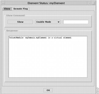
Show
Choose the Show tab on the Element Status window to execute an IOS Show command.
Figure 4-10 Element Status window—Show tab
Enter into the editable text field the particular Show command you want to send to the device, plus any arguments required. (Do not enter the word show; it will be supplied when you click the Show button.)
Select either Enable Mode or Normal Mode from the drop-down list, then click the Show button. The response will be displayed in the Response window.
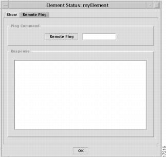
Remote Ping
Choose the Remote Ping tab to send a Ping command from the router to any device, to verify that the router can communicate with that device.
Figure 4-11 Element Status window—Ping tab
Enter the IP address of the target device into the editable text field, and click the Remote Ping button. The reply will be displayed in the Response window. If the selected router supports hostnames, you can enter either the IP address or the hostname of the target device.
Add to Analysis Baseline
Before you can test the validity of your configurations and generate a report, you must add configurations to the baseline. Since these reports are based on an analysis of connectivity paths among the routers in your network, you should include as many configurations as possible.
To create a baseline, select a domain, device or group of devices in the Element Management window and right-click the mouse anywhere in the Element Management window. Select the Add to Analysis Baseline command from the floating Options menu. Choose either Working Config or Running Config from the submenu that opens (or choose the Clear Baseline command to start with a blank baseline).
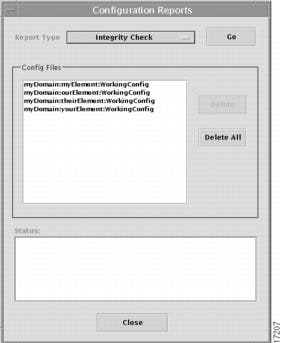
The Configuration Reports window will open.
Figure 4-12 Configuration Reports window
The Config Files pane shows a list of all of the configuration currently selected. This list is cumulative; you can close the window and reopen it, even close and reopen the Element Management window.
If you selected a domain, all configurations in the selected domain and all of its subdomains will be added.
You can selectively delete configurations from baselines by clicking on a configuration in the Config Files list and clicking the Delete button; and you can clear a baseline by choosing the Delete All button.
Generating a Configuration Report
When configurations have been added to the baseline, select the report you want from the Report Type drop-down list at the top of the Configuration Reports window and choose the Go button.
A baseline will be created from all devices in the list for which there is a valid configuration. As each element is processed, the status of the attempt to add it to the baseline will be displayed in the Status pane. When the baseline has been constructed, the report will be generated and a report window opened.
You can choose to generate any of the following reports:
•
•
•
For more information about what these reports contain, see the section "Configuration Reports" in the chapter "."
Results of any of the checks will be displayed in a spreadsheet-like grid in the report window, listing any potential problems according to device or devices involved. These reports are informational; you can choose to fix or ignore any of the problems listed.
You should periodically clean out the /tmp directory on the CNGSServer host. Reports can consume significant disk space. In addition, whenever a report is generated, a new subdirectory is created and there is a limit on the number of subdirectories that a directory can contain.
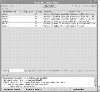
Integrity Check Report
Figure 4-13 Integrity Check window
This window lists in a spreadsheet-like grid the connectivity problems that were detected based on the router configuration files in the baseline.
When the Integrity Checks report is initially displayed, the report entries are sorted by severity (followed by warning, followed by configuration file warnings/errors.) You can click on a column header in the Results pane to sort the information displayed in the report according to the contents of that column.
For example, when you click on the Primary Device column header, the information displayed in the Results pane is sorted by the primary device names.
The Results grid is divided into the following columns:
•
•
•
•
•
•
•
•
The Filter field immediately beneath the Results grid allows you to specify search words or character strings, to filter the reports so that only a subset of entries is displayed. Use an asterisk (*) as a separator of indefinite length between character strings. The search mechanism will locate those reports which contain the search strings, in the order specified. For example, if you enter SRB*high in the Filter field and press Enter, the report will display only those devices with SRB and high somewhere in their data fields, in that order. The search mechanism is not case sensitive (srb and SRB are considered to be the same).
Adjacent to the Filter field, a status report shows how many items are displayed, how many were filtered out of the display, and how many are represented in your baseline.
To obtain more detailed information about a specific problem listed, select it and choose the Explanation button at the bottom of the report.
You can also see a summary of all of the problems found in all of the devices, by choosing the Summary Report button at the bottom of the Integrity Check Report window.
To return to the Integrity Check display from either the detailed explanation or the Summary Report, click the Parent button at the top of the window.
Click the New View button at the top of the window to open another view of this report, so that you can filter for different strings, or sort by a different column.
This report window was originally developed as part of the Netsys suite of management tools. Several elements that remain on the window have no function in the Cisco IP Manager software: the Show Suppressed Row(s) checkbox; Highlight Primary and Highlight Secondary buttons, and the No Comparison Performed prompt in the upper right corner.
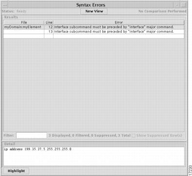
Syntax Check Report
The Syntax Errors report lists all configuration files containing syntax errors, tells where in the file the error is located, and describes what the error is.
Figure 4-14 Syntax Errors Report
When the Syntax Errors report is displayed, the Results grid has the following column headings:
File—name of file in which the syntax error was found.
Line—location in the file (line number) where the syntax error was found.
Error—description of the error.
See the appendix "" for a complete list of possible syntax errors.
Controls on this window, such as the New View button and the Filter field, are described in the section "Integrity Check Report."
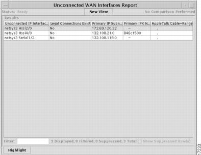
Unconnected WAN Interfaces Report
The Unconnected WAN Interfaces report provides a list of all IP interfaces that do not match up with other interfaces in the baseline.
Figure 4-15 Unconnected WAN Interfaces Report
When the Unconnected WAN Interfaces report is displayed, the Results grid has the following column headings (use the horizontal scrollbar to see them all):
Unconnected IP Interfaces—names of the routers and IP interfaces they use.
Legal Connections Exist—if a connection exists, the entry in this column is Yes, otherwise it is No.
Primary IP Subnet—primary IP subnet address.
Primary IPX Net—primary IPX network address.
AppleTalk Cable-Range—range of network numbers (IP addresses) that can be used on an AppleTalk network.
Other elements on this window, such as the New View button and the Filter field, are described in the section "Integrity Check Report."
Deleting Domains and Elements
To delete a domain or an element, right click on its name in the data tree and choose the Delete command from the floating menu that opens. Or, select multiple domains and devices then right click on any one of the selected names and choose the Delete command. When deleting multiple items, a confirmation dialog will be displayed; click the OK button to confirm. If the deleted items remain in the Element Management window's data tree, choose the Refresh All command (or select the parent node and choose the Refresh Selection command) from the View menu.
A domain must be empty before you can delete it.