Downloads |
 Feedback Feedback
|
Table Of Contents
Configuring and Monitoring LANE Services
Understand Required LANE Components
Create a Master LAN Emulation Configuration Server (LECS)
Create a Backup LAN Emulation Configuration Server (LECS)
Create LAN Emulation Clients (LECs)
Where You Should End Up—Verification
Configuring and Monitoring LANE Services
As the network administrator, you have notified that the company will be expanding to include two new buildings. These buildings will house additional engineers and other employees that the company plans on hiring.
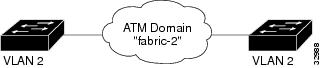
Your current network configuration consists of two segments. On each segment, a VLAN exists for the Marketing department, called VLAN2. Both segments belong to the same VTP domain, called "San Jose." See Figure 7-1.
In this scenario, you want to connect these VLANs through an ATM cloud by creating an ATM VLAN.
Note
The network design used in this scenario is intended to illustrate how to use Campus Manager applications to manage your network, not as guidelines for how to design your network. Consult the network design guidelines for that type of information.
Figure 7-1 Current Network Configuration with San Jose VTP Domain
To do this, refer to these sections:
•
What You Need—Prerequisites
Before beginning, make sure you do the following:
•
•
•
In this scenario, you will use the following applications:
•
•
Understand Required LANE Components
Before beginning, make sure you understand the components required for LANE to function:
•
•
•
See "LANE Components" in "Configuring and Monitoring LANE Services" for detailed informationabout these components and their requirements.
Prepare the ATM Devices
To prepare the ATM devices for LANE:
Step 1
Step 2
Step 3
Step 4
Step 5
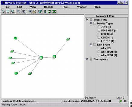
The ANI Server requires SNMP and ILMI for proper discovery of ATM devices. If the ATM devices do not appear on the topology view, you may need to increase the SNMP timeout values. Do not increase the SNMP timeout for all devices because the discovery process will take much longer. For more information about increasing the SNMP timeout, refer to the Getting Started with the CiscoWorks2000 Server publication.
Figure 7-2 Topology View of ATM Domain Showing ATM Devices
Create a Master LAN Emulation Configuration Server (LECS)
If the ATM Domain does not already have a master LECS, you must create one. To do so, perform the following steps:
Step 1
Step 2
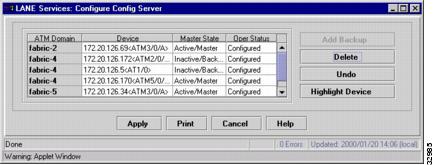
Topology Services displays the host name and module/port number of the best candidate for the LECS as the default entry in the Device column. You can accept this choice or click on the down arrow to select another device.
Notice that the Oper Status (operating status) column shows Not Configured. This means that the LECS has not been configured. Once you click Apply, the configuration will be updated on the switch and the status will change to Configured.
Step 3
Step 4
Figure 7-3 Configure Config Server Window
Create a Backup LAN Emulation Configuration Server (LECS)
If a master LECS already exists, you can add a backup LECS by performing the following steps:
Step 1
Step 2
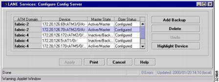
The Master State column should show the state of the master LECS as Active/Master and the Oper Status should show Configured.
Step 3
Another row is added. Notice that the fabric name is the same as the fabric you selected.Topology Services displays the host name and module/port number of the best candidate for the backup LECS as the default entry in the Device column. You can accept this choice or click on the down arrow to select another device.
Step 4
Notice that the Oper Status (operating status) column shows Inactive/Backup. This means that the LECS has not been configured yet. After the configuration is updated on the switch, the status will change to Active/Backup.
Figure 7-4 Configure Config Server Window for Backup LECS
How to Do It—Procedure
Before creating an ATM-VLAN, make sure you have at least one LECS in the ATM domain. See the "Prepare the ATM Devices" section.
Refer to the procedures to create an ATM-VLAN:
1.
2.
Create a LE/Broadcast Server
Because you have already created VLAN 2 on each segment in your network, you need to add the LE/Broadcast server capability to the VLAN to extend the VLAN across the ATM network.
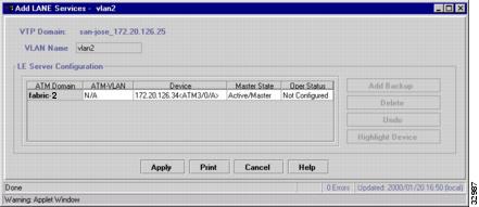
To create a LE/Broadcast server for VLAN 2:
Step 1
Step 2
See Table 7-1 for help filling in the required information.
Step 3
Topology Services displays the host name and module/port number of the best candidate for the LE/Broadcast server as the default entry in the Device column. You can accept this choice or click on the down arrow to select another device.
Step 4
Step 5
Step 6
Another row is added. Notice that the fabric name is the same as the fabric you selected. Topology Services displays the host name and module/port number of the best candidate for the backup LE/Broadcast server as the default entry in the Device column. You can accept this choice or click on the down arrow to select another device.
Step 7
Notice that the Oper Status (operational status) column shows Not Configured. This means that the backup LE/Broadcast server has not been configured yet. After the configuration is updated on the switch, the status will change to Configured and the Master State column will show Inactive/Backup.
After creating a new LE Broadcast Server, an entry for a standalone ATM VLAN will immediately appear in the Standalone ATM VLANs folder inside the appropriate ATM fabric in the ATM Domains folder. To see the appropriate hybrid ATM VLAN entry for the VLAN (under the appropriate VTP domain) for which the LE Broadcast Server was created, you must first create a LAN Emulation Client for the new ATM VLAN and rediscovery your network.
Figure 7-5 Add LANE Services Window
.
Create LAN Emulation Clients (LECs)
You must create an LEC on each required ATM device that will participate in the ATM-VLAN and map the VLAN to the ATM VLAN across the ATM interfaces (LECs).
Campus Manager does not support these functions. You can do this in these two ways:
•
•
Refer to the device Command Reference or Configuration guide for more information about how to do this.
Rediscover the Network
If you want to view the changes you have made to your network before the next automatically scheduled discovery cycle, perform a manual discovery that is limited to the desired ATM domain.
To rediscover the ATM domain, perform these steps:
Step 1
Step 2
Step 3
Step 4
Where You Should End Up—Verification
You have configured LANE components to your network and have added LANE capability to VLAN 2. Now you need to make sure that they are correctly configured and that the switches are operational (green icon on the topology view).
To check this, display the LANE components in your network:
Step 1
Notice that a cloud icon has been added to the name to denote that the VLAN is now an ATM-VLAN.
Step 2
Step 3
Step 4