Feedback Feedback
|
Table Of Contents
Managing Physical and Logical Network Services with Topology Services
Starting and Navigating in Topology Services
Using the Topology Services Main Window
Using Network Topology Windows
Inter-Switch Link (ISL) Protocol
Differences Between Traditional and Virtual LANs (VLANs)
LAN Emulation Configuration (LANE)
ATM LANE Configuration Guidelines
Managing Physical and Logical Network Services with Topology Services
Topology Services is an application that enables you to discover, view, and monitor these physical and logical services on your network:
•
ATM domains
•
•
•
•
•
The following topics provide you with information about:
•
Starting and Navigating in Topology Services
From the CiscoWorks2000 desktop, select Campus Manager > Topology Services. The Topology Services main window appears.
Topology Services provides multiple windows for performing tasks. Refer to the following sections for a description of the elements in the windows:
•
•
Using the Topology Services Main Window
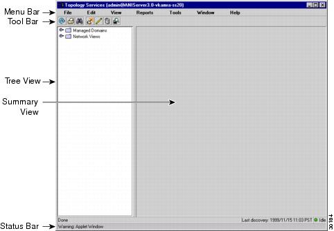
The Topology Services main window displays VTP domains, VLANs, and ATM domains discovered in your network (see Figure 2-1). Topology Services provides several methods for accessing network information or status, as shown in Table 2-1.
Figure 2-1 Topology Services Main Window
Using Network Topology Windows
You can use network topology windows to see different aspects of your network. Only devices and links discovered in your network are displayed in the network topology windows. As you use Topology Services, listed devices and links change dynamically to display devices and links that ANI discovers in your network.
You can access all network and domain views from Topology Services by clicking on the corresponding folder in the left pane of the main Topology Services window:
•
•
–
–
–
–
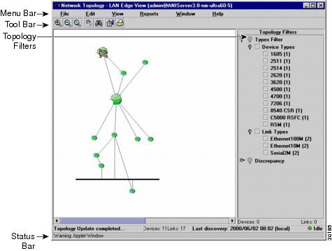
The Network Topology windows provide various abstract views of your network, but the windows share common features (see Figure 2-2). Table 2-2 describes the Network Topology window components.
Figure 2-2 Network Topology Windows
Using Topology Services
Table 2-3 describes the main tasks you can perform with Topology Services.
Topology Services Concepts
You should understand these concepts when using Topology Services:
•
ANI Server
Campus Manager uses the asynchronous network interface (ANI) Server to automatically discover devices in your network. ANI Server is a service provided by the CiscoWorks2000 Server. This service must be set before you can use Campus Manager. Refer to the Getting Started with the CiscoWorks2000 Server guide for details about this service.
Supported Protocols
The following concepts are important for understanding how to use Topology Services:
•
•
You must make sure that the applicable protocols are implemented correctly in your network; otherwise, the information gathered might be incomplete.
VLAN Trunk Protocol
To implement VLANs in your network, you must activate VLAN Trunk Protocol (VTP) on all switches that will participate in the VLAN-segmented network. Using VTP, each switch in server mode advertises its management domain on its trunk ports, its configuration revision number, and known VLANs and their specific parameters. A VTP domain is made up of one or more interconnected devices that share the same VTP domain name. A switch can be configured for only one VTP domain.
VTP servers and clients maintain all VLANs everywhere within the VTP domain. A VTP domain defines the boundary of the specified VLAN. Servers also transmit information through trunks to other attached switches and receive updates from those trunks.
Spanning-Tree Protocol
Spanning-Tree Protocol is a link management protocol that provides path redundancy while preventing undesirable loops in the network. For an Ethernet network to function properly, only one active path can exist between two stations.
Multiple active paths between stations cause loops in the network. If a loop exists in the network topology, the potential exists for duplicate messages. When loops occur, some switches detect stations appearing on both sides of the switch. This condition confuses the forwarding algorithm and allows duplicate frames to be forwarded.
To provide path redundancy, Spanning-Tree Protocol defines a tree that spans all switches in an extended network. Spanning-Tree Protocol forces certain redundant data paths into a standby (blocked) state. If one network segment in the Spanning-Tree Protocol becomes unreachable, or if Spanning-Tree Protocol costs change, the spanning-tree algorithm reconfigures the spanning-tree topology and reestablishes the link by activating the standby path.
Spanning-Tree Protocol operation is transparent to end stations, which are unaware whether they are connected to a single LAN segment or a switched LAN of multiple segments.
Inter-Switch Link (ISL) Protocol
Inter-Switch Link (ISL) is a Cisco-proprietary protocol that maintains VLAN information as traffic flows between switches and routers.
You can pass VLAN information between devices by configuring links between the switches. If you want a link to carry more than one VLAN, you must use ISL. ISL is a Cisco-proprietary tagging protocol that allows VLAN trunking by maintaining VLAN information as traffic flows between switches and routers. To use ISL, you must configure the ports on both sides of the link as trunk ports.
When two VTP domains are interconnected using an ISL trunk between two LAN switches, by default, no VLAN traffic is forwarded. However, you can configure the ports on each switch to receive and forward specific VLANs. To configure the ports, the VLANs on either side of the ISL trunk must be identical and share the same VLAN characteristics such as VLAN names, VLAN indexes, and so on.
IEEE 802.1Q
IEEE 802.1Q is the industry-standard encapsulation protocol to carry traffic for multiple VLANs over a single link.
LAN Emulation (LANE)
LANE services are commonly required to provide Ethernet connectivity across ATM backbones. LANE emulates the layer-2 logical services of Ethernet networks across ATM devices, such as the LightStream 1010 ATM switches and the LANE modules in the Catalyst 5000 series switches. Specifically, LANE provides the broadcast and multicast functions of Ethernet networks across these ATM backbones.
Token Ring Bridging Protocols
Two Token Ring bridging protocols are supported:
•
If the trCRF is configured for SRB, ports configured in the trCRF are members of the broadcast domain for the non-source route (NSR) broadcast issued by stations seeking their designation station. Stations belonging to a different trCRF do not receive these broadcasts.
When the NSR broadcast fails to find the destination station, the station sends an All Routes Explorer (ARE) frame. The ARE propagates to all trCRFs belonging to the trBRF. This broadcast frame is not propagated to trCRFs belonging to other trBRFs unless there is an external connection between the trBRFs.
•
If the trCRF is configured for SRT, non-source route (NSR) broadcasts are forwarded to other trCRFs (within the same parent trBRF). The trBRF transparently bridges these NSR broadcasts to other trCRFs configured for SRT. All NSR- and NSR-configured trCRF children view the trBRF as a traditional transparent bridge.
VLANs
A VLAN is a group of end stations with a common set of requirements, independent of physical location. VLANs have the same attributes as a physical LAN but allow you to group end stations even if they are not located physically on the same LAN segment.
VLANs allow you to group ports on a switch to limit unicast, multicast, and broadcast traffic flooding. Flooded traffic originating from a particular VLAN is only flooded out other ports belonging to that VLAN.
Differences Between Traditional and Virtual LANs (VLANs)
A traditional LAN is configured according to the physical infrastructure it is connecting. Users are grouped based on their location in relation to the hub they are connected to and how the cable is run to the wiring closet. Segmentation is typically provided by the routers that connect each shared hub.
A virtual LAN (VLAN) is a switched network that is logically segmented by functions, project teams, or applications regardless of the physical location of users. Each switch port can be assigned to a different VLAN. Ports in a VLAN share broadcasts; ports that do not belong to that VLAN do not share these broadcasts.
Switches remove the physical constraints imposed by a shared-hub architecture because they logically group users and ports across the enterprise. As a replacement for shared hubs, switches remove the physical barriers imposed in each wiring closet.
Advantages of VLANs
VLANs provide:
•
•
•
Simplification of Moves, Adds, and Changes
Adds, moves, and changes are some of the greatest expenses in managing a network. Many moves require recabling and almost all moves require new station addressing and hub and router reconfiguration.
VLANs simplify adds, moves, and changes. VLAN users can share the same network address space regardless of their location. If a group of VLAN users move but remain in the same VLAN connected to a switch port, their network addresses do not change. If a user moves from one location to another but stays in the same VLAN, the router configuration does not need to be modified.
Controlled Broadcast Activity
Broadcast traffic occurs in every network. If incorrectly managed, broadcasts can seriously degrade network performance or even bring down an entire network. Broadcast traffic in one VLAN is not transmitted outside that VLAN, which substantially reduces overall broadcast traffic, frees bandwidth for real user traffic, and lowers the vulnerability of the network to broadcast storms.
You can control the size of broadcast domains by regulating the size of their associated VLANs and by restricting both the number of switch ports in a VLAN and the number of people using these ports.
You can also assign VLANs based on the application type and the amount of application broadcasts. You can place users sharing a broadcast-intensive application in the same VLAN group and distribute the application across the campus.
Workgroup and Network Security
You can use VLANs to provide security firewalls, restrict individual user access, flag any unwanted network intrusion, and control the size and composition of the broadcast domain.
You can increase security by segmenting the network into distinct broadcast groups. VLANs provide the following advantages:
•
•
VLAN Components
VLAN components are:
•
Switches are the entry point for end-station devices into the switched domain and provide the intelligence to group users, ports, or logical addresses into common communities of interest. LAN switches also increase performance and dedicated bandwidth across the network.
You can group ports and users into communities using a single switch or connected switches. By grouping ports and users across multiple switches, VLANs can span single-building infrastructures, interconnected buildings, or campus networks. Each switch can make filtering and forwarding decisions by packet and communicate this information to other switches and routers within the network.
•
Routers provide policy-based control, broadcast management, and route processing and distribution. They also provide the communication between VLANs and VLAN access to shared resources such as servers and hosts. Routers connect to other parts of the network that are either logically segmented into subnets or require access to remote sites across wide area links.
•
The VLAN transport enables information exchange between interconnected switches and routers on the corporate backbone. The backbone acts as the aggregation point for large volumes of traffic. It also carries end-user VLAN information and identification between switches, routers, and directly attached servers. Within the backbone, high-bandwidth, high-capacity links carry the traffic throughout the enterprise.
Types of VLANs Supported
Topology Services supports three types of VLANs:
Ethernet VLANs
An Ethernet VLAN is the typical VLAN design, which consists of a logical group of end-stations, independent of physical location on an Ethernet network. Catalyst switches support a port-centric, or static, VLAN configuration. All end stations connected to ports belonging to the same VLAN are assigned to the same Ethernet VLAN.
ATM VLANs
An ATM VLAN spans an ATM network bridging two or more Ethernet VLANs using LAN Emulation (LANE). LANE provides connectivity between ATM-attached devices by emulating a LAN over an ATM cloud, including the following:
•
•
Because LANE connectivity is defined at the MAC layer, upper protocol layer functions of LAN applications can continue unchanged when the devices join ATM VLANs.
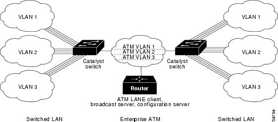
An ATM network can support multiple independent ATM VLANs. End-system membership in any of the ATM VLANs is independent of the physical location of the end system, which simplifies hardware moves and changes. In addition, end-stations can move easily from one ATM VLAN to another, whether or not the hardware moves.
Figure 2-3 ATM LANE to Extend VLANs Example
Token Ring VLANs
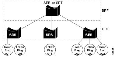
A Token Ring VLAN is a set of rings interconnected through a bridging function. There are two Token Ring VLAN types defined in VTP version 2:
•
•
Multiple trCRFs can be interconnected using a single Token Ring Bridge Relay Function (trBRF).
Figure 2-4 Token Ring VLANs
LAN Emulation Configuration (LANE)
LAN Emulation (LANE) enables existing applications to access an ATM network as if they were operating over traditional LANs, such as Ethernet or Token Ring. LANE allows LAN users to benefit from ATM without modifying end-system hardware or software. End systems on LANs can connect to other end systems on LANs, as well as to ATM-attached servers, routers, and switches.
LANE reconciles the differences between ATM and LAN protocols by masking the connection setup and handshaking functions required by the ATM switch. LANE basically bridges LAN traffic across ATM. LANE has specific hardware requirements. For details, refer to your switch or router documentation.
LANE Components
LANE is defined on a client-server LAN model For LANE services to be fully functional, the components in Table 2-4 must be configured.
Table 2-4 LANE Component Descriptions
LANE Configuration Server (LECS)
The LECS acts as the registration point for each emulated LAN within the ATM backbone. It contains the database that determines to which an ATM VLAN client belongs. Clients consult the configuration server to determine which ATM VLAN it should join. The configuration server returns the ATM address of the LE Server (LES) for that ATM VLAN, and also maintains the LES redundancy information.
Cisco recommends having one master configuration server per ATM domain. Campus Manager does not support more than one master configuration server, but you can have additional backup configuration servers.
LE Server (LES)1
Cisco's implementation combines the LE and Broadcast servers (LE/Broadcast servers); however, the functions remain separate.
The LE server acts as the control center. Provides joining, address resolution, and address registration services to the LE clients in that ATM VLAN. Clients can register destination unicast and multicast MAC addresses with the LE server. The LE server also handles LANE ARP (LE ARP) requests and responses.
Clients can communicate directly with one another only when they are connected to the same LE server.
Cisco recommends having one active master combined LE/Broadcast server per ATM VLAN. Multiple LE/Broadcast servers can exist on the same physical ATM network where each server supports a different ATM-VLAN. You can have additional backup LE/Broadcast servers.
Broadcast Server1
Cisco's implementation combines the LE and
Broadcast servers (LE/Broadcast servers); however, the functions remain separate.The Broadcast server sequences and distributes multicast and broadcast packets and handles unicast flooding.
Cisco recommends having one active master combined LE/Broadcast server per ATM VLAN. You can have additional backup LE/Broadcast servers.
Client
Emulates a LAN interface to higher-layer protocols and applications. Forwards data to other LANE clients and performs LANE address-resolution functions.
Can be a member of only one ATM VLAN.
An ATM device can have several LE clients—one client for each ATM VLAN of which it is a member.
Campus Manager does not support the creation of LECs and the mapping of VLANs to ATM-VLANs across ATM interfaces (LECs). You can do this in these two ways:
•
•
1 In Cisco's implementation of LANE, the LE server and broadcast server are one entity. In this document, references to an LE server include the broadcast server.
How LANE Works
ATM is a connection-oriented service, while LAN is a broadcast medium. ATM uses connection-oriented service with point-to-point signaling or multipoint signaling between source and destination devices. LAN-based protocol suites use connectionless service and broadcasts to enable source devices to find one or more destination devices.
Using LANE, LAN broadcasts are emulated as ATM unicasts. LANE emulates a broadcast environment such as IEEE 802.3 Ethernet or 802.5 Token Ring on top of an ATM network that is a point-to-point environment. Client devices, such as routers, ATM workstations, and LAN switches use LES functions to emulate a LAN across ATM.
LANE defines a service interface for network layer protocols that is identical to existing MAC layers. No changes are required to existing upper layer protocols and applications. Data sent across the ATM network is encapsulated in the appropriate LAN MAC packets. LANE essentially bridges LAN traffic across ATM and defines the operation of an emulated LAN.
LANE does not emulate every particular physical or data-link characteristic. For example, it does not support carrier sense multiple access collision detect (CSMA/CD) for either Ethernet or Token Ring. LANE on the ATM switch router supports only the IP protocol.
LANE can be implemented on these devices:
•
•
•
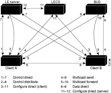
Communication among LANE components is ordinarily handled by several types of switched virtual channel circuits (VCCs). Some VCCs are unidirectional; others are bidirectional. Some are point-to-point; others are point-to-multipoint. (See Figure 2-5.)
Figure 2-5 LANE Virtual Circuit Types
The elements in Figure 2-5 function as follows:
•
•
•
•
•
•
ATM LANE Configuration Guidelines
Use these guidelines when configuring LANE:
•
•
•
•
•
•
•
•
•
•
•
•
Note
•
•
•
•
In the event of an ATM network failure, there can be multiple master LECs and multiple active LES/BUSs for the same ELAN, resulting in a partitioned network. Clients continue to operate normally, but transmission between different partitions of the network is not possible. The system recovers when the network break is repaired.
VTP Domains
Before using Topology Services to monitor the VLANs in your network, consider your VTP domain design. This is an essential step because Topology Services was designed for running on networks using VTP services.
A VTP domain is made up of one or more interconnected devices that share the same VTP domain name. A switch can be configured to be in only one VTP domain, and each VLAN has a name that is unique within a management domain.
Typically, you use a VTP domain to ease administrative control of your network or to account for physical boundaries within your network. However, you can set up as many or as few VTP domains as are appropriate for your administrative needs. Consider that VTP is transmitted on all trunk connections, including ISL, IEEE 802.1Q, 802.10, and LANE.
VLAN Trunk Protocol (VTP)
Using VLAN Trunk Protocol (VTP), each switch in server mode advertises its management domain on its trunk ports, its configuration revision number, and its known VLANs and their specific parameters. Therefore, a new VLAN must be configured on only one device in the management domain, and the information is automatically learned by all the other devices (not in VTP transparent mode) in the same management domain. Once a device learns about a VLAN, it receives all frames on that VLAN from any trunk port and, if appropriate, forwards them to each of its other trunk ports.
Two versions of VTP are supported—VTP 1 and VTP 2. Every switch in the VTP domain must use the same VTP version. The VTP version is important if you use Campus Manager in a Token Ring environment because you must use version 2 with Token Ring devices. Verify the software image version of all of the devices in your network to make sure they support VTP 2.
Components of VTP Domains
Within a VTP domain, you can configure switches as follows:
•
•
•
Your VTP domain structure influences the behavior of Topology Services. Use these guidelines to ensure that your network is set up correctly for Topology Services:
•
One VTP Server—Multiple VTP Clients
At least one VTP server for each VTP domain is required. Cisco recommends that you configure the other devices as VTP clients, especially if you have a large network. Having only one VTP server maintains VLAN consistency across the network.
Multiple VTP Servers
For multiple VTP servers, consider that the device with the most recent configuration revision number controls VTP advertisements. The configuration revision number associated with a device's known set of VLANs (in one management domain). This revision number can be compared to another device's configuration revision number (for the same management domain) to determine which is more recent. This revision number is incriminated when a device is reconfigured to define a new VLAN, delete an existing VLAN, suspend or resume an existing VLAN, or modify the parameters of an existing VLAN.
If a network has two or more VTP servers that are not connected by Inter-Switch Link (ISL), the VLAN configuration on those servers may not be synchronized. In this case, Topology Services reads the VLAN information from the VTP server with the latest revision number. You must ensure that the most recent changes to VLANs are made on the VTP server with the highest configuration revision number.
VTP Server—VTP Transparent
To prevent your devices from participating in VTP, configure them as VTP transparent. When you create a VLAN on a VTP transparent switch, the VLAN is local to that switch, and is not known to other devices in the network.
Topology Services reads VLAN information from the VTP servers and transparent switches in your network. Topology Services attempts to correlate VLAN information between transparent switches and those known to the VTP Server. If a transparent switch is participating in a VLAN identical to the VLAN known to the VTP Server, the VLAN is shown belonging to each.
Provided that you have at least one VTP server in your network, you can create local VLANs on transparent switches. However, you lose a verifiable consolidated view of the VLAN states of your switches. A switch in transparent mode does not communicate its VLAN state to a server nor does it accept changes to its VLAN state from the server.
VTP Transparent Only
If you use Topology Services in a VTP domain that contains VTP transparent switches and no VTP servers, Topology Services will not discover any VLANs in the network. You must have a VTP Server in the VTP domain.
ATM Domains
You can view and monitor ATM domain status, including standalone ELANs, in your network. You can also use the ATM Domain network views to obtain detail about devices in each ATM domain.
The ANI server discovers the ATM switches and end hosts, and all physical and logical links among those switches and hosts. These components comprise the ATM domain.
An ATM domain is a group of interconnected ATM switches and ATM end hosts that can be discovered with the Interim Local Management Interface (ILMI) neighbor discovery mechanism. Switches within the ATM network must support AToM MIB (RFC 1695).
ATM End host contains an ATM network interface adapter. Examples of ATM endpoints are workstations, routers, data service units (DSUs), LAN switches, and video coder-decoder (CODEC).
ATM switches:
1.
2.
3.